

Page 1
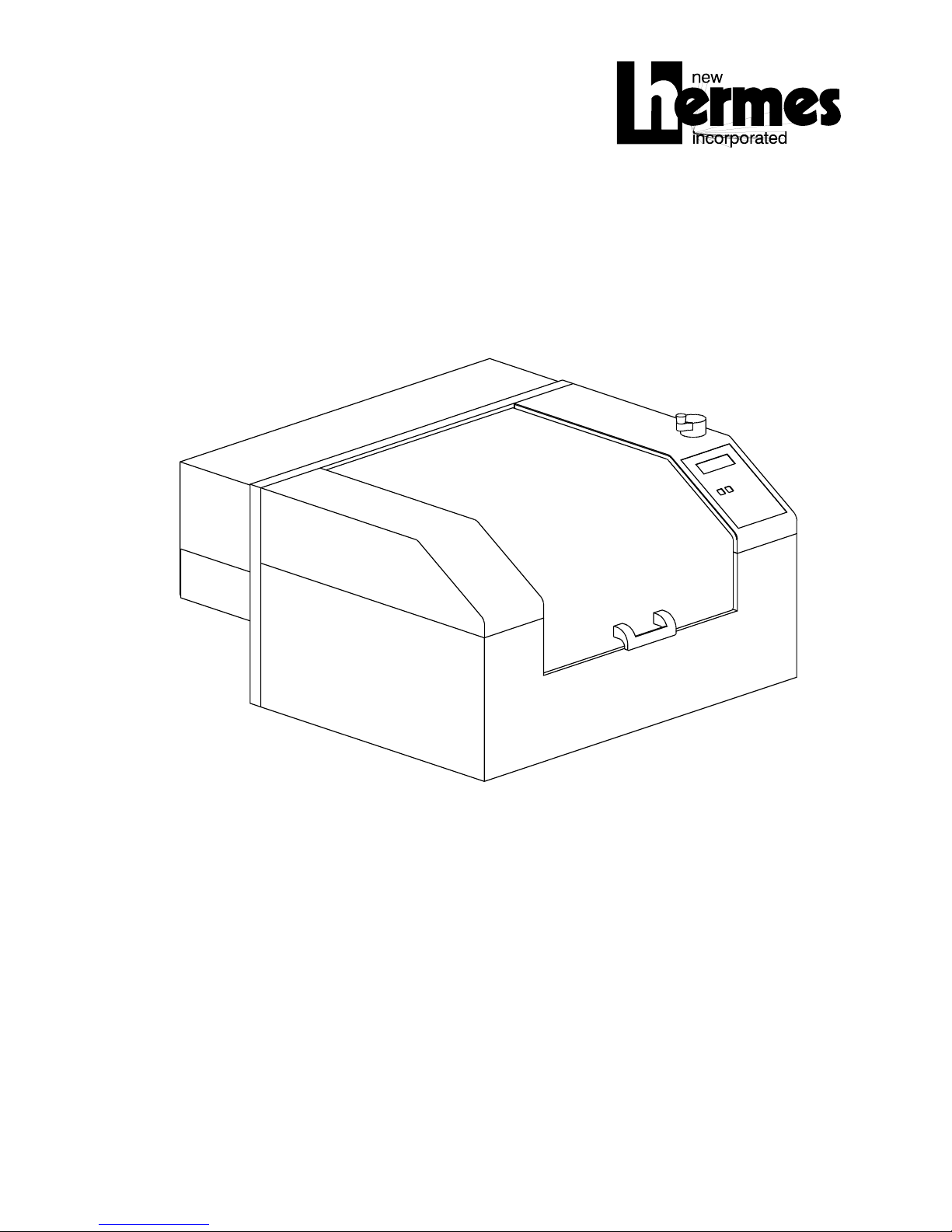
VANGUARD OPTIMA
USER’S MANUAL
Page 2

Page 3

VANGUARD OPTIMA
Laser Engraving and Cutting System
User’s Guide
Manufactured by:
Universal Laser Systems, Inc.
16008 North 81st Street
Scottsdale, AZ 85260
Phone: 480-483-1214
Fax: 480-483-5620
August 1998
Page 4

Notice
This publication and its contents are proprietary to Universal Laser Systems, Inc. (ULS), and are
intended solely for the contractual use of ULS, Inc. customers.
While reasonable efforts have been made to assure the accuracy of this manual, ULS shall not
be liable for errors contained herein or for incidental or consequential damage in connection
with the furnishing, performance, or use of this material.
ULS reserves the right to revise this manual and make changes from time to time without
obligation by ULS to notify any person of such revision or changes.
ULS does not assume any liability arising out of the application or use of any products, circuits,
or software described herein. Neither does it convey a license under its patent rights nor the
patent rights of others.
This publication and its contents may not be reproduced, copied, transmitted, or distributed in
any form, or by any means, radio, electronic, mechanical, photocopying, scanning, facsimile, or
otherwise, or for any other purpose, without the prior written permission of ULS.
ULS provides no warranties whatsoever on any software used in connection with a ULS Laser
Engraving System, express or implied. Neither does it guarantee software compatibility with any
off-the-shelf software package or any software program that has not been written by ULS.
Intended use of this system must be followed within the guidelines of this manual. In no event
will ULS be liable for any damages caused, in whole or in part, by customer, or for any
economic loss, physical injury, lost revenue, lost profits, lost savings or other indirect, incidental,
special or consequential damages incurred by any person, even if ULS has been advised of the
possibility of such damages or claims.
HP is a registered trademark of Hewlett-Packard Company.
Windows is a registered trademark of Microsoft Corporation.
Macintosh is a registered trademark of Apple Computer Company.
PostScript, Photoshop, and Streamline are registered trademarks of Adobe Systems Inc.
CorelDraw is a registered trademark of Corel Corporation.
AutoCad is a registered trademark of Autodesk Inc.
© Universal Laser Systems Inc., 1998
All Rights Reserved
Page 5

Introduction
Thank you for purchasing the Vanguard Optima Laser System. Being the first desktop laser
engraving and cutting system ever created, the Optima stands out among the crowd. It has
been designed to combine flexibility and full featured performance without sacrificing simplicity,
ease of use, and ease of maintenance. Using advanced engineering and design features, the
Vanguard Optima is truly one-of-a-kind. Actually, the Optima is such a breakthrough in
technology that it is more than just a laser system, it is a precision engraving and cutting device
used as a tool for the imagination.
To begin with, we highly recommend that this entire manual be read before attempting to use
the laser system. The manual includes important information about the safety, assembly, use,
and maintenance of the Vanguard Optima. We cannot overemphasize the importance of
reading the owner's manual completely.
Where to get HELP:
If it is necessary to call for technical assistance, please call our Technical Support
Department at (602)483-1214. Please be prepared to answer our questions by following the
procedures below, as this will allow us to provide assistance in a prompt and efficient manner:
• Take a moment to write down all of the pertinent information about the computer
being used with the laser cutting and engraving system such as software, operating
system and computer type.
• Our technical support staff will ask you for your company name and the laser
systems serial number. The serial number tag is located on the back of the machine
in the lower right corner. There is a second serial tag located behind the front door
on the right side when you open it. This will prevent you from having to get to the
back of the machine to read the serial number.
• Try to recreate the problem and write down the circumstances in which the problem
occurred. This will help our technical staff tremendously.
• If possible call from a phone that is close to the laser engraving system so that the
system can be operated while talking with our technical support staff.
Page 6

Page 7

Contents
SECTION 1 - Safety .........................................................................1-1
General Safety........................................................................................ 1-1
Laser Safety............................................................................................ 1-2
Laser Safety Labels ................................................................................ 1-3
Other Safety Labels ................................................................................ 1-6
FCC Compliance .................................................................................... 1-7
EU Compliance (CE) ............................................................................. 1-8
SECTION 2 - Installation........................................................................... 2-1
Operating Environment........................................................................... 2-1
Electrical Requirements.......................................................................... 2-2
Exhaust Requirements ........................................................................... 2-3
Unpacking and Assembling the System ................................................. 2-4
Computer Requirements......................................................................... 2-5
Software Suggestions............................................................................. 2-5
Font Requirements ................................................................................. 2-6
Making the Connections ......................................................................... 2-7
SECTION 3 - The Printer Driver ............................................................. 3-1
How the Computer Controls the Laser System....................................... 3-1
Installing the Windows 95 Printer Driver ................................................. 3-2
Driver Controls........................................................................................ 3-3
SECTION 4 - Graphics Software............................................................ 4-1
Software Setup ....................................................................................... 4-1
Speed Optimizing ................................................................................... 4-4
Page 8

Bitmapped / Scanned Images................................................................. 4-4
Encapsulated Postscript (EPS) Images .................................................. 4-6
Postscript (PS) Images ........................................................................... 4-6
SECTION 5 - System Operation .....................................................5-1
How it Works........................................................................................... 5-1
The Control Panel................................................................................... 5-4
The Menu System................................................................................... 5-7
Menu Descriptions ................................................................................ 5-10
Focusing ............................................................................................... 5-22
SECTION 6 - Running the System Step by Step ..........................6-1
Powering Up ........................................................................................... 6-1
Loading and Positioning the Material...................................................... 6-1
Focusing Methods .................................................................................. 6-2
Creating the Graphic............................................................................... 6-3
Setting the Drivers Properties ................................................................. 6-3
Downloading the File .............................................................................. 6-5
Starting the Engraving Process .............................................................. 6-5
Material Removing and Reloading.......................................................... 6-6
SECTION 7 - Accessories...............................................................7-1
- Rotary Fixture ......................................................................................... 7-1
Rubber Stamps....................................................................................... 7-1
SECTION 8 - Sample Materials ......................................................8-1
Safety ..................................................................................................... 8-1
Acrylic - Cast and Extruded .................................................................... 8-3
Acrylic - Mirrored..................................................................................... 8-5
Anodized Aluminum................................................................................ 8-7
Page 9

Brass - Coated........................................................................................ 8-8
Corian / Avonite / Fountainhead ............................................................. 8-9
Cork ...................................................................................................... 8-10
Delrin (Seal Press)................................................................................ 8-11
Glass / Crystal ...................................................................................... 8-12
Leather ................................................................................................. 8-13
Marble................................................................................................... 8-14
Mat Board ............................................................................................. 8-15
Melamine .............................................................................................. 8-16
Melamine - Photo / Clipart Engraving ................................................... 8-17
Plastic - Engravers Microsurfaced ........................................................ 8-18
Rubber Stamps / Pre-Inked Stamps ..................................................... 8-19
Sign Vinyl.............................................................................................. 8-20
Wood / Wood Inlay ............................................................................... 8-21
SECTION 9 - Maintenance ....................................................................... 9-1
Suggested Cleaning and Maintenance Supplies .................................... 9-1
System Cleaning..................................................................................... 9-3
Optics Cleaning ...................................................................................... 9-3
Adjustments and Lubrication................................................................... 9-6
Electronic Upgrading .............................................................................. 9-6
Maintenance Schedule ........................................................................... 9-6
SECTION 10 - Appendices
Warranty .................................................................................................... A
Specifications............................................................................................. B
Using DOS Based Programs .....................................................................C
Using Macintosh Computers......................................................................D
Serial Cable Requirements........................................................................ E
Software Anomalies................................................................................... F
Page 10
1-1
SECTION 1
Safety
This section describes hazards that may occur if the laser system is installed or used
improperly. Failure to follow these guidelines can result in injury to yourself, others, or may
cause severe damage to the equipment. Use, misuse, or abuse of the equipment in a manner
other than what is described in this manual may increase this risk. Operation and care of the
laser system must be followed in strict accordance to this manual.
General Safety
• Exposure to the laser beam may cause physical burns and can cause severe eye
damage. Proper use and care of this system are essential to safe operation.
• Never operate the laser system without constant supervision of the cutting and
engraving process. Exposure to the laser beam may cause ignition of combustible
materials and start a fire. A properly maintained fire extinguisher should be kept on hand at
all times.
• A properly configured, installed, maintained, and operating fume/smoke exhaust
system is mandatory when operating the laser system. Fumes and smoke from the
engraving process must be extracted from the laser system and exhausted outside.
• Some materials, when engraved or cut with a laser, can produce toxic and caustic
fumes. We suggest that you obtain the Material Safety Data Sheet (MSDS) from the
materials manufacturer. The MSDS discloses all of the hazards when handling or
processing that material. The law requires all manufacturers to provide this information to
anyone who requests it. DISCONTINUE processing any material that shows signs of
chemical deterioration of the laser system. Systems damaged from this abuse will NOT be
covered under warranty.
• Dangerous voltages are present within the electronics and laser enclosures of this
system. Although access to these areas is not necessary during normal use, if it becomes
necessary to open one of these enclosures for service reasons please remember to unplug
the machine first.
• Care should be taken when moving or lifting the laser system. The laser system
weighs about 150 lbs. (68 kg.). Obtain assistance from 1 or 2 additional people when lifting
or carrying the system. Severe bodily injury may occur if improper lifting techniques are
applied. Be careful not to drop the laser system. Not only can it cause bodily harm, but it
will also severely damage the equipment and render it inoperable.
Page 11
1-2 Safety
• The laser system is specifically designed to comply with CDRH performance
requirements under 21 CFR 1040.10 and 1040.11. CDRH is the Center for the Devices of
Radiological Health division of the Food and Drug Administration (FDA). This laser system
also complies with CE (European Community) safety regulations. No guarantees of
suitability or safety are provided for any use other than those specified by Universal Laser
Systems Inc. Please contact Universal Laser Systems Inc. with any questions concerning
laser safety before operating this system.
Laser Safety
The laser system contains a sealed carbon dioxide (CO2) laser that produces intense and
invisible laser radiation at a wavelength of 10.6 microns in the infrared spectrum. This laser
system contains a C02 laser in a Class I enclosure. However, due to the presence of a visible
red laser diode, the entire laser system is classified as Class 3a.
• The entire system is completely enclosed with a protective housing. This will completely
contain the invisible C02 laser beam under normal use. However, the red diode laser is a
visible laser beam. DO NOT STARE INTO BEAM OR VIEW DIRECTLY WITH OPTICAL
INSTRUMENTS.
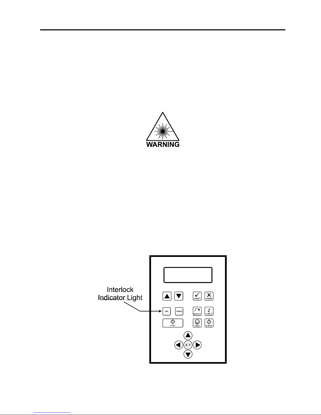
• The user door(s) are safety interlocked and will disable the CO2 laser beam from firing when
the user door(s) are opened. The control panel will also display a flashing “RED” light to
visually indicate that the safety interlock system has been activated. The red diode laser
beam is NOT safety interlocked and can be activated with the door(s) either open or closed.
Page 12
Safety 1-3
Do not modify or disable any safety feature of this system. Do not operate any system
that has had its safety features modified, disabled, or removed. Improper use of controls
and adjustments, or performance of procedures other than those specified in this manual, may
invalidate the safety of this system.
This laser system is equipped with a visible red diode pointing laser and is considered a Class
3A device by CDRH and CE. Do not stare into the beam or view directly with any optical
instrument.
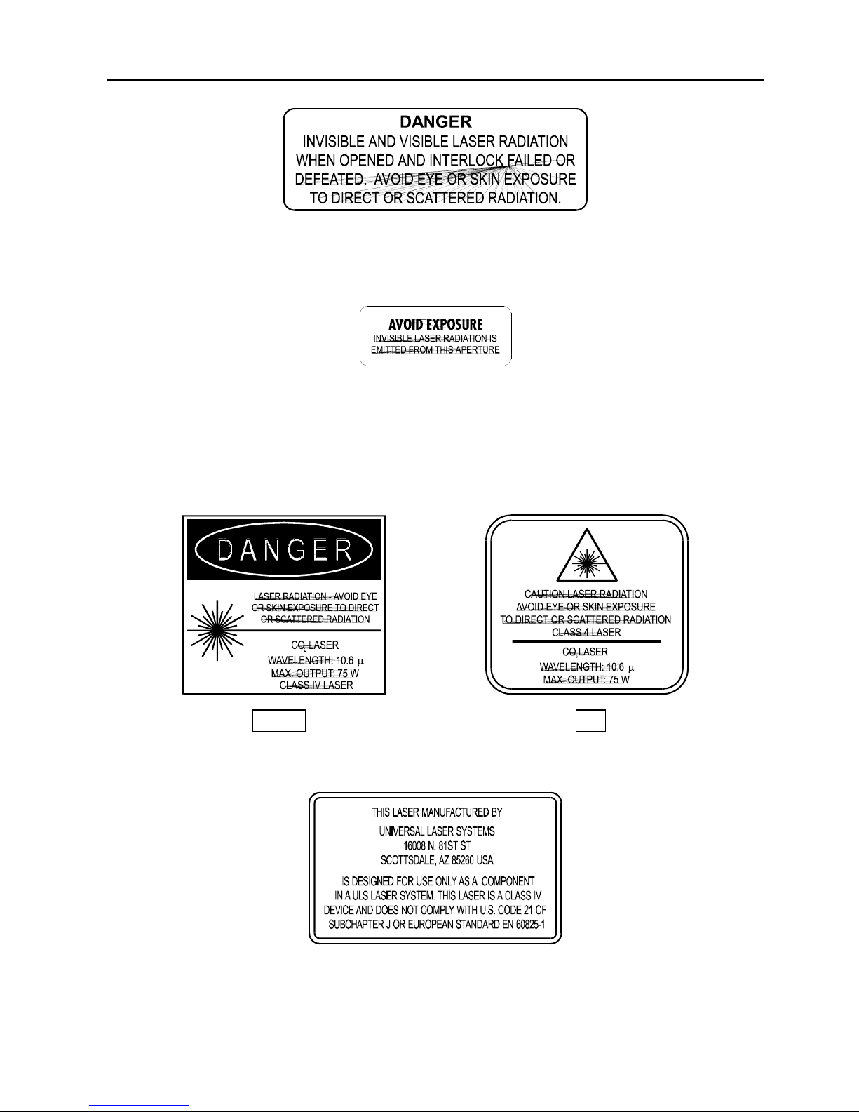
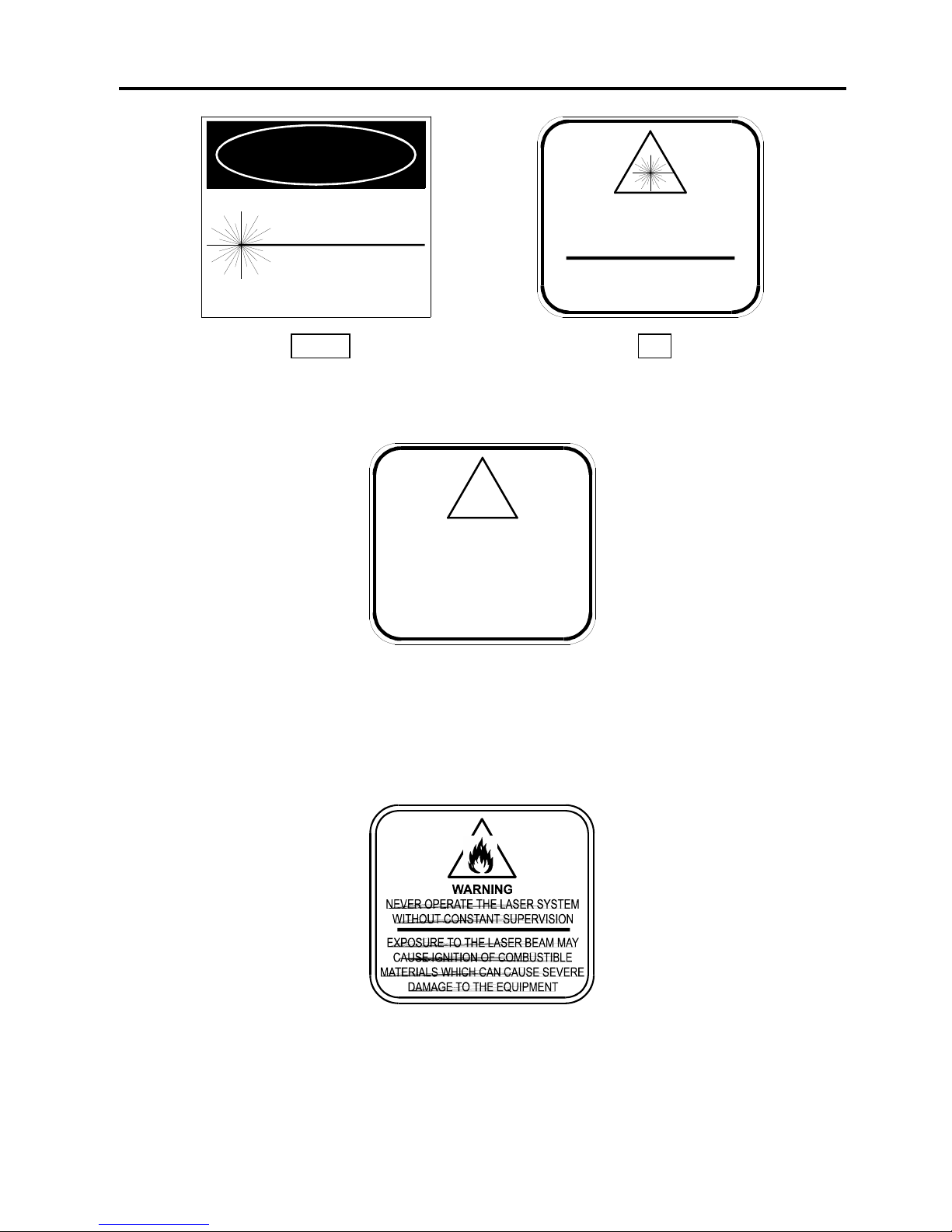
Laser Safety Labels
CDRH and CE regulations require all laser manufacturers to affix warning labels in specific
locations throughout the equipment. The following warning labels are placed on the laser
system for your safety. DO NOT remove them for any reason. If the labels become damaged
or have been removed for any reason, DO NOT OPERATE the laser system and immediately
contact Universal Laser Systems Inc. for a free replacement.
Locations (1): On the back of the system next to the serial number tag. Visible when viewing
the laser system from the backside.
Page 13
1-4 Safety
Locations (2): One is on the top door and visible under normal operation. The other is located
inside the laser system on the back panel, visible when the top door is opened.
Locations (3): One is next to the Beam Window where the laser beam enters the engraving area
inside the laser system and is visible when the top door is opened. The second one is located
inside the output optics cover of the laser tube assembly that is not visible under normal
operating conditions. The third is located on the outside of the laser tube assembly. The second
and third locations are only visible if the laser tube assembly is removed for service and is not
visible under normal operating conditions.
Locations (1): Affixed to the back of the laser tube assembly. Not visible under normal
operating conditions. Only visible if laser tube is removed for service.
Locations (1): Affixed to the back of the laser tube assembly. Not visible under normal
operating conditions. Only visible if laser tube assembly is removed for service.
CDRH
CE
Page 14
Safety 1-5
LASER RADIATION - AVOID
DIRECT EYE EXPOSURE
CLASS IIIa LASER PRODUCT
LASER DIODE
WAVELENGTH: 630-680 nm
MAX. OUTPUT: 5 mW
D A N G E R
Or
CAUTION LASER RADIATION
DO NOT STARE INTO BEAM OR VIEW
DIRECTLY WITH OPTICAL INSTRUMENTS
CLASS 3A LASER PRODUCT
LASER DIODE
WAVELENGTH: 630-680 nm
MAX. OUTPUT: 5 mW
Locations (1): On the outside of the top door. Visible from the outside under normal operating
conditions with the door closed.
!
WARNING
THIS LASER SYSTEM CONTAINS A
CO LASER IN A CLASS I ENCLOSURE.
THE LASER SYSTEM HAS BEEN
CLASSIFIED AS CLASS 3a DUE
TO THE PRESENCE OF A
VISIBLE LASER DIODE.
2
Locations (1): On the outside of the top door. Visible from the outside under normal operating
conditions with the door closed.
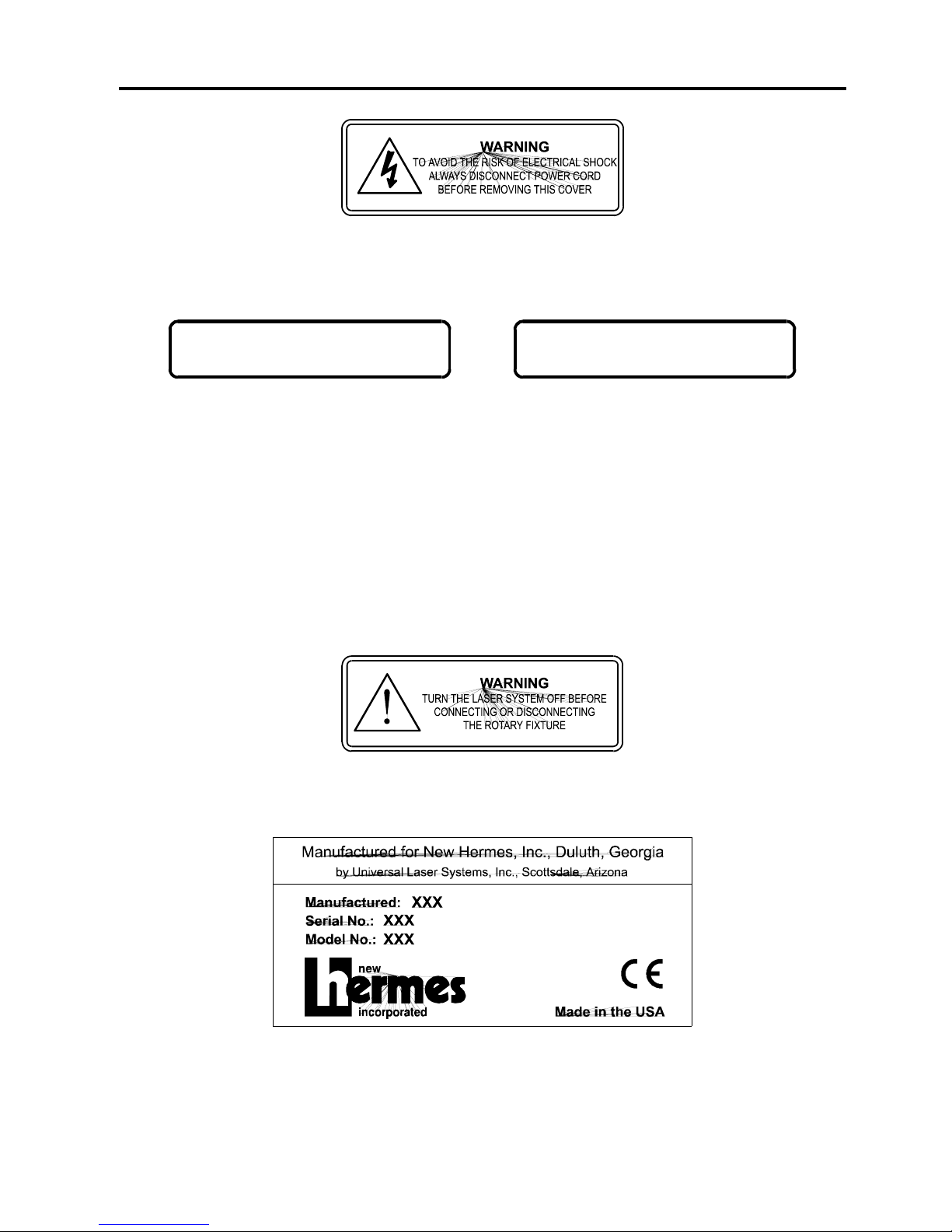
Other Safety Labels
Locations (1): On the outside of the top door. Visible from the outside under normal operating
conditions with the door closed.
CDRH
CE
Page 15
1-6 Safety
Locations (2): One is on the back of the laser system’s cooling fan cover. Visible from the
outside under normal operating conditions when viewed from the backside of the system. The
other is on the plastic shield over the back of the power entry module.
INPUT POWER:
110 VAC; 50/60 Hz; 10 A
INPUT POWER:
220 VAC; 50/60 Hz; 5 A
DOMESTIC INTERNATIONAL
OR
Locations (1): On the side of the laser system next to the ON/OFF switch and plug receptacle.
Visible from the outside under normal operating conditions.
Locations (1): Inside of the laser systems cooling fan cover next to the chassis ground green
wire. Not visible under normal operating conditions. Visible only when cover is removed for
servicing only.
Locations (1): On the outside motor cover of the optional Rotary Fixture. Visible under normal
operating conditions.
Serial Tag
Locations (1): On the back side of the laser system in the lower right corner if viewing the
machine from the back side. Visible under normal operating conditions.
Page 16

Safety 1-7
FCC Compliance
This ULS laser system has been tested and found to comply with Federal Communication
Commission (FCC) directives regarding Electromagnetic Compatibility (EMC). In accordance
with these directives ULS is required to provide the following information to its customers.
FCC Compliance Statement and Warnings
This device Complied with FCC Rules Part 15. Operation is subject to the following two
conditions:
1. This device may not cause harmful interference, and
2. This device must accept any interference received, including interference that may
cause undesired operation.
This equipment has been tested and found to comply with the limits for a Class A digital device
as set forth in Part 15 of the FCC Rules. These limits are designed to provide reasonable
protection against harmful interference when the equipment is operated in a commercial
environment. This equipment generates, uses and can radiate radio frequency energy and, if
not installed and used in accordance with manufacturer’s instructions, may cause harmful
interference to radio communications. Operation of this equipment in a residential area is likely
to cause harmful interference in which case the user will be required to correct the interference
at his or her own expense.
Users should be aware that changes or modifications to this equipment not expressly approved
by the manufacturer could void the user’s authority to operate the equipment.
This equipment has been type tested and found to comply with the limits for a Computing
Device per FCC part 15, using shielded cables. Shielded cables must be used in order to insure
compliance with FCC regulations.
Page 17
1-8 Safety
EU Compliance (CE)
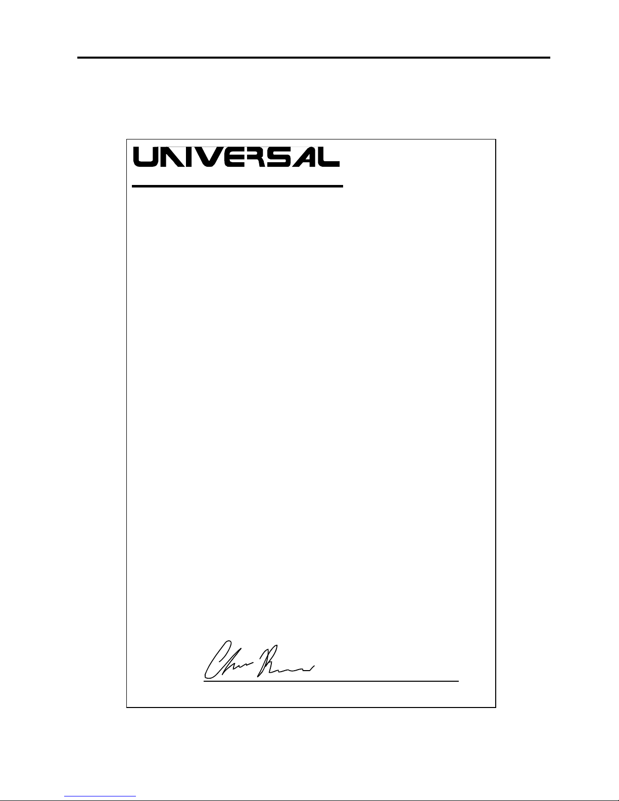
EU Declaration of Conformity
LASER SYSTEMS INC .
Product Identification: Optima Laser Cutting and Engraving System
Manufacturer: Universal Laser Systems, Inc.
16008 N. 81st St.
Scottsdale, AZ 85260
USA
Universal Laser Systems, Inc. hereby declares that the equipment specified
below is in conformity with the following directives:
89/336/EEC (EMC Directive)
73/23/EEC (Low Voltage Directive)
89/392/EEC (Machinery Directive)
based on the standards listed.
Standards Used:
Safety:
EN 60950: 1995
EN 60825: 1994 (Class IIIa)
EMC:
EN 55022: 1995 (Class A)
EN 50082-1: 1992
EN 60801-2: 1993 (6kV CD, 8kV AD)
EN 61000-3-2: 1996 (class A)
EN 61000-3-3: 1995
EN 61000-4-3: 1997 (3 V/m)
EN 61000-4-4: 1995 (2 kV power line, 0.5 kV signal line)
EN 61000-4-5: 1996 (class 2)
Manufacturer’s Contact:
Chris Risser, Compliance Engineer
1998
Signature Date
Warning - This is a Class A product. In a domestic environment this
product may cause radio interference in which case the user may be
required to take adequate measures.
Page 18
2-1
SECTION 2
Installation
Proper operating conditions are vital to a safe and productive environment. From choosing the
right location to plugging in the connectors, this section describes the ideal environment and
setup of the laser system.
Operating Environment
Please follow the guidelines below. Failure to provide the proper operating environment for the
can cause damage to the laser system as well as your computer.
• Room temperature must remain between 65 and 85 degrees Fahrenheit or between 17 and
27 degrees Celsius.
• Humidity levels must be less than 70% or where the temperature is at least 10 degrees
above the dewpoint temperature. Dew formation can electrically short out the laser system
and/or your computer and is very dangerous.
• Avoid dusty or dirty air environments. Keep the laser system isolated from any type of
sandblasting, sanding equipment, or any other machinery that produces airborne particles.
Install the laser system in an office type environment.
• Avoid small, enclosed, non-ventilated areas. Some materials, after laser engraving or
cutting, continue emitting fumes for several minutes after processing. Having these
materials present in a confined, unventilated room can contaminate the room.
• Choose a place which provides the shortest and most direct path to the exhaust ductwork
(not provided). Refer to exhaust requirements later on in this section.
• Have a work table or storage area next to or nearby the laser system. This prevents the
operator from using the system as a table or storage facility.
• Do not move, push, lean on, or jar the laser system while it is engraving. The material you
are engraving can shift and produce unsatisfactory results.
• If planning to connect the laser engraving system to a computer through the parallel port,
choose a location where the computer can be placed within 10 feet of the machine since this
is the maximum recommended parallel cable length.
• If connecting an additional laser system or other printer to the same computer, we
recommend the installation of an additional parallel port into the computer. DO NOT use a
manual A/B type switch box. This creates electrical noise which can cause an engraving
problem or can damage the laser system and/or the computer’s electronics.
Page 19
2-2 Installation
Electrical Requirements
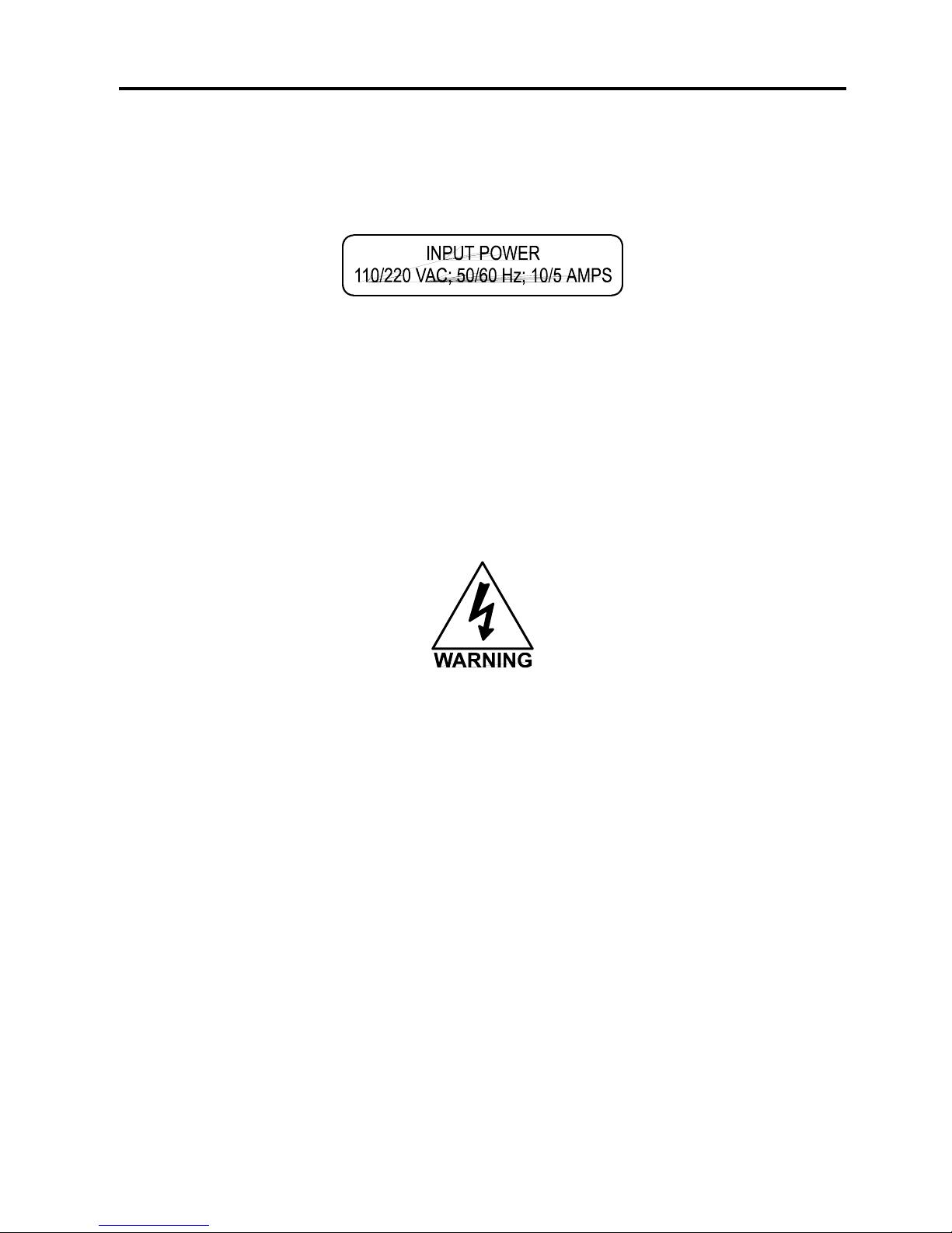
This system has the above electrical rating. Make sure that your electrical outlet is capable of
providing the proper voltage, frequency and amperage that this system requires.
Noisy or unstable electricity as well as voltage spikes can cause interference with the
electronics of the laser system. Connect the laser system to a dedicated electrical line if this is
a problem in your building.
The electronics of the laser system has built-in surge suppression. However, it is a good
practice to plug the laser system into a high quality surge suppressor and then plug the surge
suppressor into a properly grounded outlet.
Never remove the ground lead to the electrical cord and plug the system into a nongrounded outlet. This is very dangerous and can lead to a severe, if not fatal, electrical
shock. Always plug the system into a 3 prong grounded outlet.
If electrical power fluctuations, brown outs, or constant power outages are a problem in your
area, an electrical line stabilizer, UPS (Uninterruptible Power Supply), or backup generator
might be required. If installing any of these devices, make sure that they meet the electrical
requirements of the laser system.
If there is any type of electrical problem present, please contact a locally licensed electrical
contractor to correct the problem. Repairs to the laser system will NOT be under warrantee if
the laser system is damaged by an improper or incorrect electrical supply as well as voltage
spikes and surges. It is your responsibility to provide a suitable electrical supply.
Page 20
Installation 2-3
Exhaust Requirements
To properly exhaust fumes and smoke from the laser engraving system during operation,
it is necessary to provide an exhaust unit moving a minimum of 200 CFM (cubic feet per
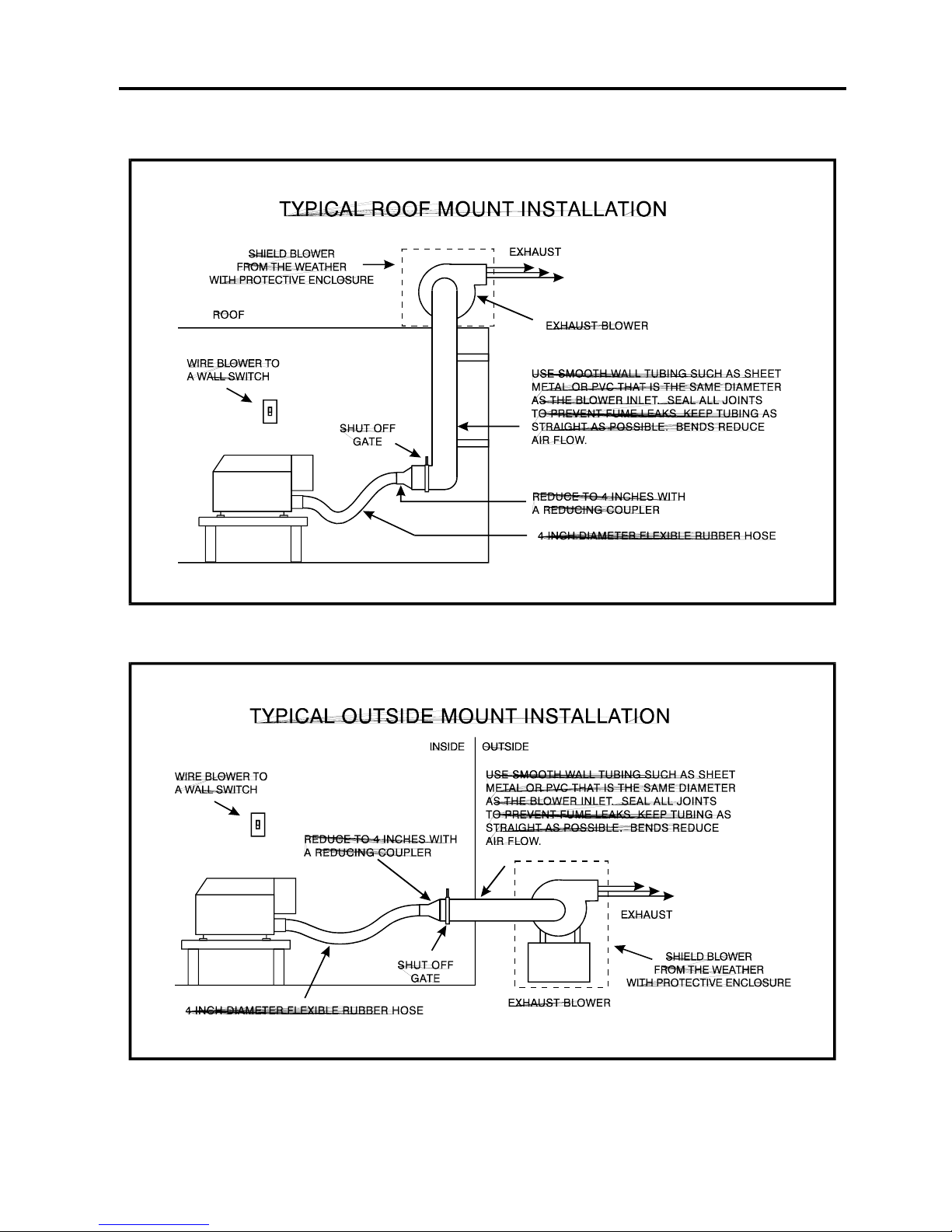
minute) at 6 inches of static pressure (inches of water). Please refer to the sample diagram
on the next page.
The blower MUST be mounted on the OUTSIDE of the building either on the roof or on a
cement pad next to the building possibly mounted on vibration dampeners. Rigid tubing should
be used for 90% of the distance traveled. The tubing should be smooth walled and have as few
90 degree bends as possible. Two 45 degree bends have better air flow than one 90 degree
bend. Use tubing with a diameter that matches the blower unit (usually 6 inches/1524 mm) and
use a 6 inch(1524 mm) to 4 inch(1016 mm) reducer to couple the tubing down to 4 inches(1016
mm) to within a few feet from the laser system. Also consider installing a gate to control air flow
and to close off the exhaust from the outside environment when the laser is not in use. This is
especially useful in colder climates where it can be damaging to the laser system to have cold
air coming into it from the outside. Do not connect the rigid tubing directly to the laser system.
Use a short piece of industrial grade, wire reinforced rubber tubing to connect the end of the
gate, or rigid tubing, to the laser system. This will provide mobility and will dampen blower
vibrations. Use only a few feet because it’s spiral construction reduces air flow. Install a hose
clamp on both ends of the hose to prevent leaks and to prevent the hose from slipping off.
Have the blower wired to a wall switch in the same room.
The chart below is based on the measured distance from the outlet of the laser system to the
inlet of the exhaust blower. It assumes that you will. It is important to purchase a high pressure
blower that meets or exceeds these requirements.
Measured Distance
Blower Required
up to 25 feet / 8 meters
200 CFM @ 6 inches / 1524 mm static pressure
26 - 50 feet / 8 - 15 meters
300 CFM @ 6 inches / 1524 mm static pressure
51 - 75 feet / 15 - 23 meters
400 CFM @ 6 inches / 1524 mm static pressure
76 - 100 feet / 23 - 30 meters
500 CFM @ 6 inches / 1524 mm static pressure
Never operate the laser engraving system without a properly installed and operating
exhaust system. Some materials when cut or engraved can produce fumes that are
hazardous in concentrated amounts.
The following diagrams show typical exhaust system layouts. Use these as a guideline to
proper exhaust system installation. Although these diagrams just serve as an example, we
recommend installation of the exhaust system by a licensed contractor to meet safety and local
code requirements. Please contact a local air quality control specialist.
Page 21
2-4 Installation
Page 22

Installation 2-5
Unpacking and Assembling the System
Since packaging can change from time to time, please refer to the Unpacking and Assembly
Instructions found inside of the shipping container when you first opened it.
Computer Requirements
The following is our minimum recommended computer configuration. Using a faster computer
with more capacity will increase efficiency and throughput. Although using a computer that
does not meet our minimum recommendation might be acceptable to you, a faster computer
will definitely pay for itself in a short amount of time.
• Pentium 120 Mhz or equivalent
• 32 MB of RAM
• 2 Gigabyte hard drive or bigger
• 17 inch color VGA monitor
• 3.5” floppy disk drive
• CD-ROM Drive
• Mouse or other pointing device
• Microsoft Windows 95
• 600 DPI Optical Resolution Scanner
Remember, the laser system is an output device just like a printer is. The faster you can create
graphics and manipulate your software, the faster you can download to the laser system to
keep it producing.
Software Suggestions
The following is a list of recommended software programs. We do not endorse any particular
software program neither do we guarantee it’s full compatibility with the laser system. Please
refer to the Appendices section on known bugs/anomalies related to these particular software
programs, related versions, and ones that are not listed below.
Graphics Programs
• CorelDraw
• Macromedia Freehand
Bitmap / Scanning Software
• Adobe Photoshop
• Adobe Streamline - for raster to vector conversion
Page 23

2-6 Installation
CAD Software
• AutoCAD for Windows
• AutoCAD LT for Windows
• Autosketch for Windows
• DesignCAD for Windows
CAD users do not necessarily need Windows or Windows compatible programs. The laser
system is compatible with any program that can output standard HPGL commands whether it is
Windows based or not. Refer to the section on using DOS based CAD programs.
When a software company updates their version of their programs, it can sometimes cause
conflicts with our printer driver. Our programmers constantly test new software programs and
updated versions for compatibility. We will update our printer driver to address issues that we
have control of. For bugs or problems with your software not related to the laser system,
please contact the software manufacturer. As a courtesy to our customers, we have included a
list of phone numbers for various software companies. It can be found in the Appendices
section of this manual.
Font Requirements
True Type
We recommend using True Type fonts only. TrueType fonts are the most versatile and should
be used whenever possible. They provide the best print quality and will print well at any size.
PostScript
We do not recommend using PostScript fonts. The laser system is not a PostScript printer and
therefore has no capability of printing PostScript fonts. Sometimes a PostScript font will print if
you are running Adobe Type Manager(ATM). Adobe Type Manager converts PostScript fonts to
bitmapped fonts before sending the information to our printer driver. Using ATM does not
guarantee that the PostScript font will print properly therefore it is not recommended.
Bitmap
Bitmapped fonts only print well when used at the specific point size they were designed for.
This point size is usually indicated in the font name such as Times Roman 12. If a font is only
available in bitmap form, you must print it at the size it was created for. Scaling the font larger
will result in a more jagged looking character although scaling it smaller produces good results.
Helpful Tip
If you are having any problems printing a font and you cannot figure out what is going on, select
the font and “convert to curves” or “convert to paths” in your graphics software. This will convert
the font into a bitmapped image and will print correctly to the laser system. Refer to your
graphics software on how to convert fonts.
As you can see, we strongly recommend the use of True Type fonts only. Usually, most
graphics programs, such as CorelDraw come with hundreds of fonts that you can install. For
the average user there is more than enough to choose from.
Page 24
Installation 2-7
Making the Connections
Never connect or disconnect the printer cable while either the computer or the laser
system is powered ON. Always power down both units when connecting or disconnecting the
printer cable.
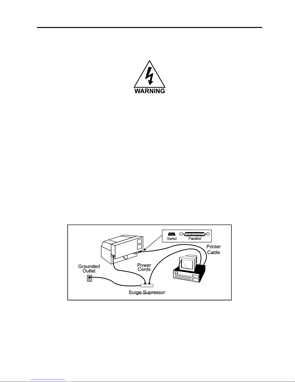
Please use the parallel cable supplied with the system. It is a 6 foot high quality shielded cable
that has a molded ferrite choke built in. If you use a printer cable other than the one provided, it
will violate the laser systems FCC and CE rating and may also cause harmful interference when
downloading files to the laser system.
Please make the following connections in the exact order described otherwise static electricity
can damage the computer and/or the laser system’s electronics.
• Connect the laser system’s power cord and the computer’s power cord to a high quality
surge suppressor and then the surge suppressor to a grounded outlet.
• Make sure both the computer and laser system are plugged in and turned OFF, then
connect the laser system to the computer using either a serial or parallel connection.
Page 25

2-8 Installation
Never connect the laser system through a manual switch type A/B switch box. If
connecting an additional laser system or other printer to the same computer, we recommend
the installation of an additional parallel port into the computer.. This creates electrical noise
which can cause an engraving problem or can damage the laser system and/or the computer’s
electronics.
Never use any device that is installed between the computers parallel port and the
parallel port of the laser system such as a ZIP drive or parallel port CD-ROM drive. This
can not only damage the laser systems electronics but it usually will not work. Again, install an
additional parallel port for other peripheral devices.
Page 26
3-1
SECTION 3
The Printer Driver
This section describes how the computer controls the laser system through the printer driver. It
defines some very important terms that you need to know in order to operate the system
correctly so please read it thoroughly.
How the Computer Controls the Laser System
The laser system is a unique type of output device. Let’s call it a very sophisticated
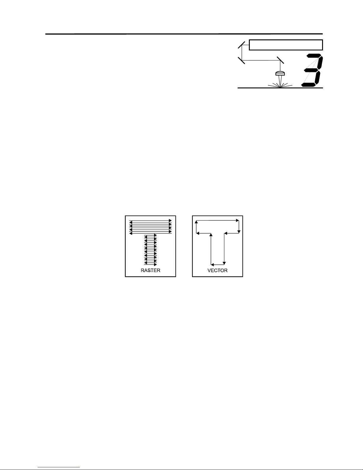
printer/plotter. A regular laser printer is a “raster” based output device and so is a bubble jet,
ink jet, and a dot matrix printer. A plotter is a “vector” based output device. The difference is
how characters and other graphics are formed. To explain what “raster” and “vector” are, let us
use the example of trying to print the letter “T”. A raster printer will make a back-and-forth
motion to create the character whereas a vector plotter will follow the path of the outline of the
character.
The laser system can actually raster the image, vector the image, or do both raster and vector
motions. The laser systems printer driver works directly with your software program to send the
correct image to the laser system. We will explain later on in this section about how this works
but for right know, we want you to understand this simple concept behind how the computer
controls the laser system:
The laser system is an output device just like a printer or plotter is. After the graphic is created
on your computer system, you print the graphic the same way you would print to a laser printer
or plot to a plotter. This information then gets sent down to the laser system through the parallel
cable and is stored in the laser systems RAM memory. Once the file is in memory, press the
“Start” button on the control panel to begin processing. The only real difference between how a
laser printer or a plotter works compared to the laser system is that the laser systems printer
driver also has controls on how much laser power as well as motion system speed is applied.
Obviously, there are many more differences between the laser system and other output
devices, but as long as the basics are clear, we can continue to learn about how the system
works.
Page 27

3-2 The Printer Driver
Installing the Windows 95 Printer Driver
Installation of the Vanguard Optima Printer Driver for Windows 95 will allow your software
program to interface with the laser system. This driver is installed the same way as most other
Windows 95 printer drivers and a simple step-by-step installation procedure is outlined below.
Complete understanding of how Windows 95 works is essential to the operation of the laser
system. Please consult the Windows 95 owners manual on its installation, use, and operation
before continuing.
1. Power ON your PC.
2. From the Task Bar click “Start”.
3. Point the mouse to the “Settings” icon, and then click the “Printers” icon.
4. Double-click on the “Add Printer” icon.
5. When the “Add Printer Wizard” appears click “Next”.
6. Select “Local Printer” and click “Next”.
7. When the “Manufacturer” and “Printers” menu list appears click “Have Disk”
(Do not look for the printer in the menu).
8. Insert the driver disk.
9. Make sure the dialog box matches the floppy drive you are using: “A:\” or “B:\”.
10. Click on “OK”.
11. When the list of “Printers” appears choose “Vanguard Optima”.
12. DO NOT click on “Have Disk” again, click on “Next”.
13. Choose the port your laser system is connected to and click on “Next”.
14. NEVER rename the printer driver as this will make it inoperable.
15. Choose if you would like to set it as your default printer and click on “Next”.
16. Select “No” when it asks to print a test page, and then click on “Finish”.
17. Click once on “Vanguard Optima” then click on “File” and drag the mouse to “Properties”.
18. The driver settings screen will appear. Click on the different tabs to get familiar with all of
the controls. Click on “OK”.
19. Driver installation is now complete. Store your driver disk in a safe place.
Page 28
The Printer Driver 3-3
Driver Controls
The Vanguard Optima Printer Driver for Windows 95 (driver for short) has the appearance of
other Windows 95 printer drivers. A thorough understanding of how Windows 95 operates is
essential to operating the drivers controls. Please refer to your Windows 95 manual or online
help screen on how to install, operate, and troubleshoot Windows 95.
General, Details, and Sharing Tabs
The tabs “General”, “Details”, and “Sharing” are tabs that Windows has control of and are
present in all Windows 95 Drivers. For information on how to use the controls located in these
tabs, please refer to your Windows 95 manual or online help screens. The “?” in upper right
hand corner of all of tabs bring you into the drivers online help screens.
Laser Settings Tab
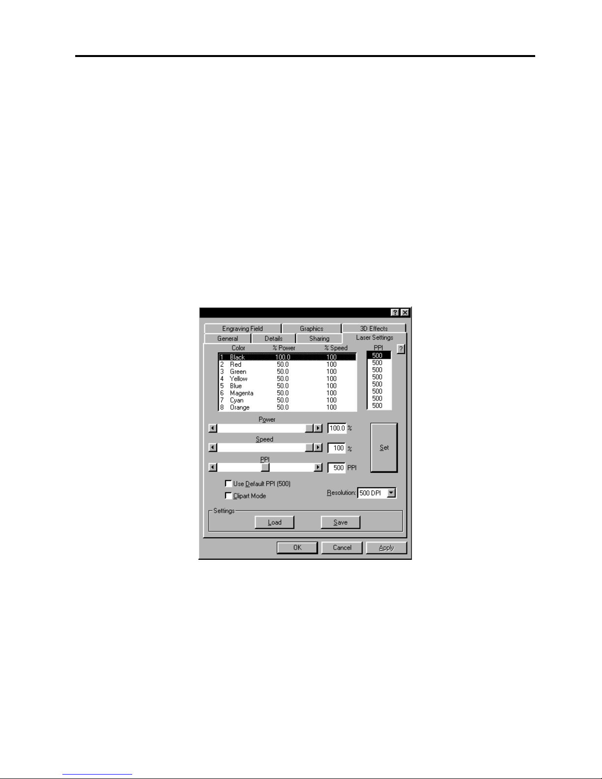
The settings in this tab are primarily used to adjust the Power, Speed, and PPI of the different
driver colors as well as setting the overall printing resolution.
NOTE: When the following sections refer to turning a switch ON, this means clicking in the box
next to the driver selection desired and a check mark will appear. Turning a switch OFF
signifies removing the check mark from the box by clicking on it again. To change the Power,
Speed, and PPI of a color, position the mouse arrow on the color and click once with the left
mouse button. This will highlight the color and allow changing of the settings by using the scroll
bars or highlighting out and typing in each setting. It is possible to set one color at a time or
click on additional colors to set more than one at a time.
Page 29

3-4 The Printer Driver
Power Setting
Laser power is controlled by assigning the percentage of power from 0 - 100% to each color
used in the graphic drawing. Since the laser is proportionally pulsed, this percentage
represents how long the laser remains on for each laser pulse fired. Basically, the power
setting is directly related to how deep the engraving will be. The Power setting is linear
meaning that 100% power will engrave or cut twice as deep as 50% power.
Speed Setting
This setting controls how fast the motion system moves in a percentage of the maximum speed
of the system. For example, 100% Speed is equivalent to 25 inches per second straight line
velocity. Therefore, 10% Speed is equal to 2.5 inches per second. When engraving, this is
the rate in which the motion system moves back and forth. When cutting, this is the speed of
the straight lines. If cutting curves or circles, the motion system automatically slows down. For
example, there is no speed difference when cutting a circle at 50% or 100% Speed because
curves will run slower than straight lines even if it is set to 100%. Proportional pulsing of the
laser will ensure that there is no difference in the depth of cut from straight lines to curves.
Power and speed work together in determining how deep the engraving will be. Higher power
settings and slower speeds will produce deeper engraving or cutting.
PPI
PPI stands for laser pulses per inch. This setting determines how many laser pulses, per linear
inch, the laser system will fire. Again, since the laser system is proportionally pulsed, all
pulses will fire equally spaced from one to the next regardless of changes in Speed, Power,
acceleration, deceleration, or the cutting of curves. For example, when setting the PPI to 500
and using a standard lens that has a laser spot size of five thousandths of an inch(.005”),
significant pulse overlap will occur. The laser system fires a laser pulse and moves over two
thousandths of an inch (that is 1 inch divided by 500). It then fires the next pulse and so on,
overlapping the pulses significantly. Lines are formed by pulsing the laser pulses so close
together and slightly overlapping each other that it appears to be a continuous line. Dot matrix
printers work the same way except the laser system uses laser pulses instead of ink dots.
When engraving, it is advisable to use a PPI setting of 500 or higher. If using less, the image
resolution of the engraving is reduced. For cutting, a PPI of 150 and above can be used.
Using less than 150 will result in the pulses being spread so far apart that they will not touch
one another. This is a good example on how to perforate paper. Increasing or decreasing the
PPI setting has absolutely no effect on engraving speed. The laser must either fire more quickly
or slowly. Experiment with using different PPI settings on some scrap material when cutting or
engraving and note the results.
Set
This button must be pressed after adjusting the Power, Speed, and PPI settings in order for
these changes to take effect. If forgetting to click on “Set”, and clicking on the “OK” button
instead, the settings will go back to the previous ones and will engrave the object with the
incorrect settings.
Page 30

The Printer Driver 3-5
Use Default PPI (500)
Turning this switch OFF will permit the changing of the PPI settings. If the switch is turned ON,
500 PPI will appear in all of the colors and will be colored gray. Since 500 PPI is the setting that
is used most often, this control sets the PPI to 500 automatically and does not allow change
unless the “Use Default PPI (500)” switch is turned back OFF.
Resolution
This setting is the image resolution of the engraving in DPI or dots per inch. There are six DPI
settings to choose from: 1000, 500, 333, 250, 200 and DRAFT. The resolution can also be
referred to as the vertical lines per inch or fill spacing. This is how many raster strokes per
vertical inch of travel that the motion system steps down to produce the engraving. Higher
resolutions will produce cleaner and deeper engraving but take longer. Lower resolutions
produce a coarser and shallower image but are quicker to engrave. Experiment with the
different settings and note the results.
Clipart Mode
This switch simulates laser printer output and is very useful if using a drawing with many colors,
shades of gray, or many outlines. It is recommended to turn this switch ON when using clipart
because there may be some underlying cutting lines hiding behind some filled areas. Having
this switch ON gives a what-you-see-is-what-you-get output very similar to laser printer output.
The entire drawing will be engraved, including all outlines, and only one power level will be
used which is black. The color change ability of the driver is essentially turned off and all colors
are engraved as different shades of gray. The laser system represents different shades of gray
by producing a halftone pattern when engraving. The halftone pattern is based upon the
Resolution setting of the driver the same way grayscale bitmaps are interpreted. Refer to the
chart on page 25 for specific details. Since clipart images use a wide variety of colors, shades,
and outlines, the only effective way of engraving these images is to have this switch turned ON.
Clipart mode also provides greater compatibility with Windows software that do not work well
with vector devices such as the Vanguard Optima laser system.
Save
A unique feature of the driver is being able to store all of the driver’ settings in a file. By clicking
on “Save”, a pop-up “Save Engraving Setup” dialog box allows you to enter in a file name for all
of the drivers settings. All settings will be stored in a file that has a “.LAS” extension. DO NOT
rename the extension because the driver will not recognize the file as a settings file if it does not
have the “.LAS” extension. These files can be stored in any directory and you can have as
many settings files as your hard drive can hold.
Load
To recall settings that you have previously saved, click on the “Load” button and choose the file
with the settings that you would like load.
Page 31
3-6 The Printer Driver
Engraving Field Tab
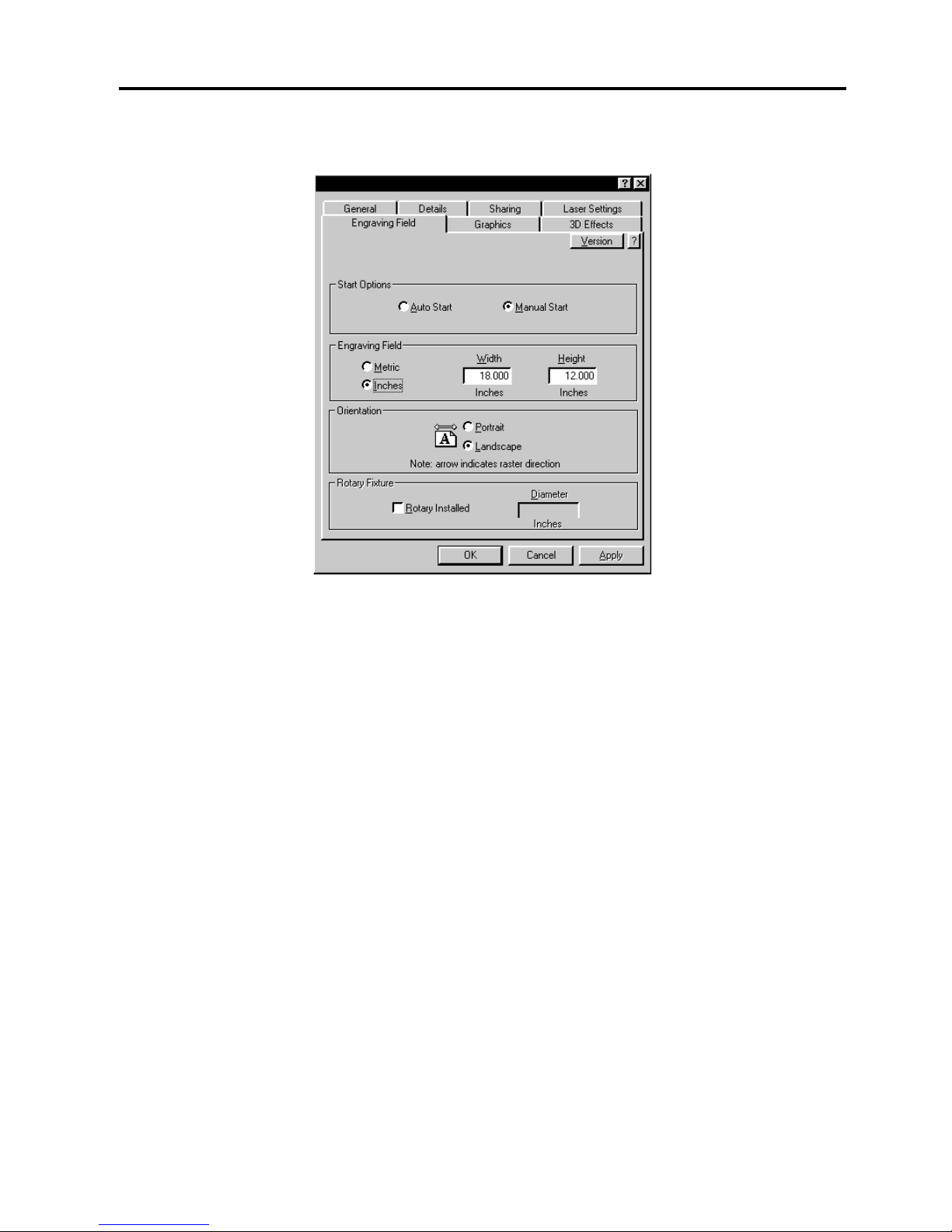
Start Options
If you would like the laser system to start engraving without having to push the “Start” button on
the control panel, select the “Auto Start” button. In order for this option to work, the laser
system must be set to the “One File Memory” mode. Refer to the “System Operation” section
on how to set up the laser system in this mode.
Before using this option, please ensure that your exhaust system is turned on, your
material is loaded into the machine and it is properly focused. The system will start
automatically as soon as the first bit of information enters the laser system from the computer
without the operator having to press the “Start” button on the control panel of the laser system.
Use extreme caution when using this function because there will be very little time to react and
get over to the laser system once you click on “OK” in the driver.
The “Manual Start” selection is the normal mode of operation of the laser system. The laser
system will not start until the entire file enters into the laser system and the operator pushes the
“Start” button on the control panel.
Engraving Field
Input here lets the driver know what page size and orientation is being used in the graphics
software. These settings MUST match the graphics software settings EXACTLY otherwise no
output, partial output, or misalignment of the graphic will occur. It is up to the operator to enter
in the correct settings. Not only must the page size be EXACT, but the orientation must be the
same also. Select the “Metric” box if metric units are desired.
Page 32
The Printer Driver 3-7
Orientation
The laser system has two modes of orientation, “Landscape” and “Portrait” mode. The
Landscape mode is the normal mode of operation. As indicated by the arrows, the landscape
mode causes the laser system to raster in the left and right direction. The Portrait mode causes
the laser system to raster from the front to the back of the laser system. One advantage to
using the Portrait mode is when using the optional Rotary Fixture later explained in Section 7 of
this manual.
Rotary Fixture
It is only necessary to use this selection if the optional Rotary Fixture has been purchased. For
full details on how to use this option, please refer to Section 7. Do not skip over to that section
until the rest of this manual, up to that section, has been read. There is important information
about the operation of the laser system that must be read before being able to fully understand
how to operate the Rotary Fixture.
Version
Clicking on the “Version” button causes the “Version” pop-up dialog box to appear. This has
information on the current driver version number as well as the drivers copyright notice.
Graphics Tab
Page 33
3-8 The Printer Driver
Dither Type
Specifies the type of dithering used in printing non-black and white bitmaps and multicolored
clipart images. Since the laser system is really acts like a black and white printer (laser ON is
considered black and laser OFF is considered white), grayscale or color photographs(bitmaps),
as well as multicolored clipart images get turned into dithered images when reproduced by the
laser system. This process is very similar to how newspaper photographs as well as laser
printer photographs are printed.
Choose “Halftone” if you want the images to print with a halftone screen that has a preset
pattern that is based on the “Resolution” selection located in the “Laser Settings” tab in the
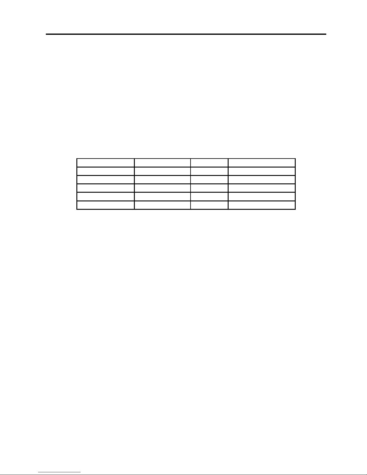
driver. The chart below describes that screen angle, shape, and lines per inch pattern applied
for the different DPI resolution choices in the driver. These are fixed patterns that cannot be
altered.
RESOLUTION
ANGLE
SHAPE
LINES PER INCH
1000
45 DEGREES
ROUND
180
500
45 DEGREES
ROUND
90
333
45 DEGREES
ROUND
60
250
45 DEGREES
ROUND
45
200
45 DEGREES
ROUND
36
Choose “Error Diffusion” if you would like the black and white pixels to be scattered in a
random pattern to represent shading. This randomized dither pattern is unlike the fixed pattern
of a “Halftone” screen and can be adjusted.
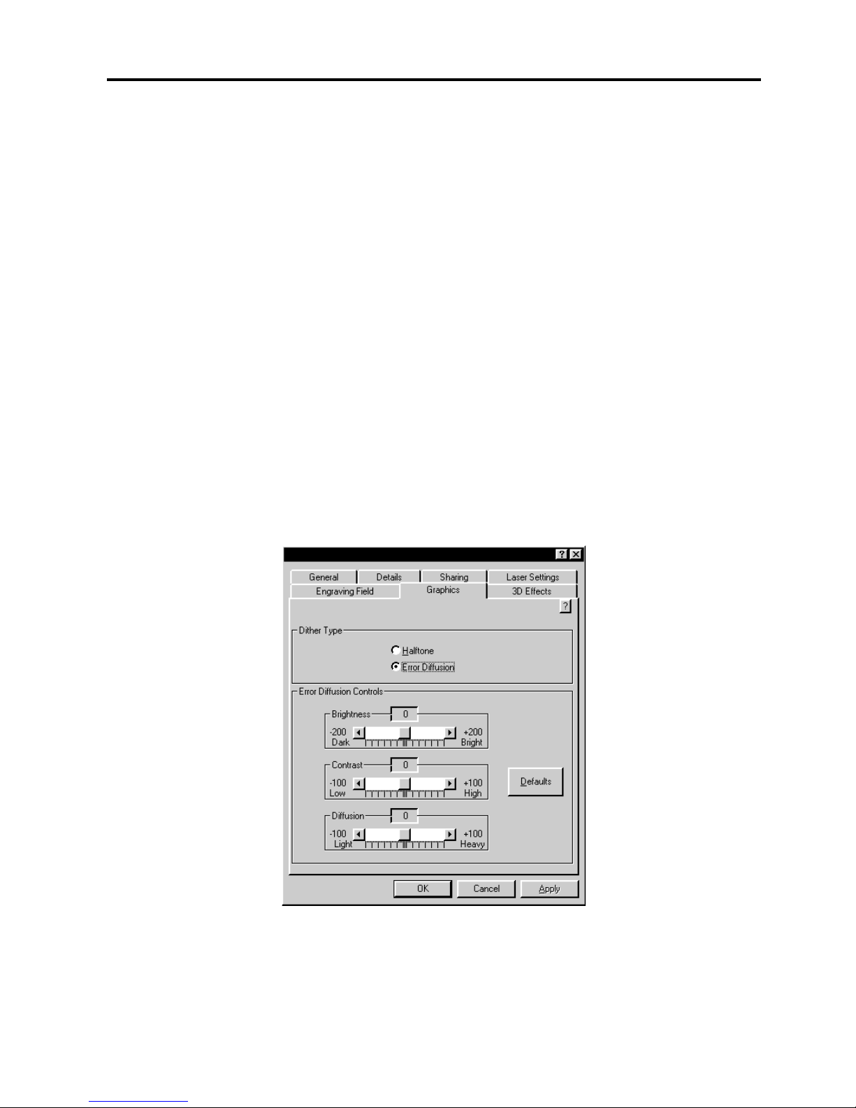
Error Diffusion Controls
When you select “Error Diffusion” this section becomes enabled allowing you to adjust 3
settings: Brightness, Contrast, and Diffusion.
“Brightness” is similar to the brightness control in most photo editing software. Adjusting the
slider to the “Bright” side brightens each pixel in the bitmap one shade of gray for each
increment. Adjusting the slider to the “Dark” side darkens each pixel in the bitmap one shade of
gray for each decrement.
“Contrast” is also similar to the contrast control in most photo editing software. Adjusting the
slider to the “High” side increases the contrast of the image by making the lighter colors brighter
and the darker colors darker which decreases the amount of gray colors. Sliding it to the “Low”
side decreases the contrast of the image by making the lighter colors darker and the darker
colors lighter which increases the amount of gray colors.
“Diffusion” controls the amount of graininess or “noise” level. Adjusting the slider to the
“Heavy” side increases the noise level thus causing the image to appear more “noisy”. Sliding it
to the “Light” side reduces the noise level and causes the image to appear more solid and have
less “noise”.
Page 34
The Printer Driver 3-9
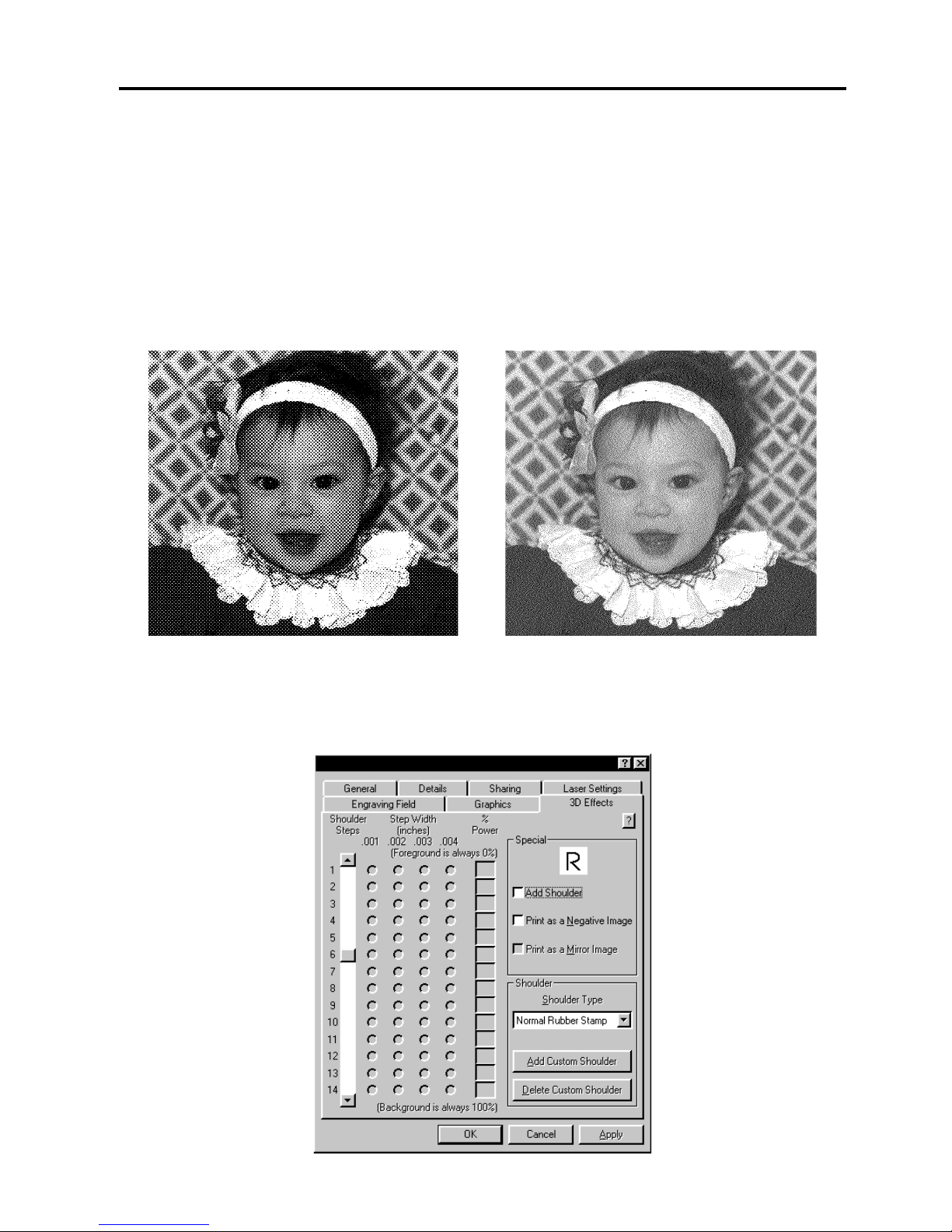
The “Error Diffusion” method should work in all software programs available because its pattern
is entirely created by the driver. However the “Halftone” methods pattern is partially created by
the driver and partially created by the software program you are using. If your software program
does not support this type of printing, then the image will look like a solid black and white image
without any dot pattern at all. If this happens, use the “Error Diffusion” selection to print the
image.
There is much more to laser engraving photographs and clipart images than stated above.
Please refer to the section on "Bitmapped Images” for a more thorough description of how to
use, manipulate, and engrave these types of images.
Halftone Screen Diffusion Dither
3D Effects Tab
Page 35
3-10 The Printer Driver
3D Effects
This option enables the laser system to raster engrave materials in a three dimensional fashion
where the image appears to be “chiseled” or “sunken”. The beam appears to have engraved
the material on an angle but in actuality it is a precise control of laser power that creates this
appearance. It only has an effect on raster images and no effect on vectors. This option is also
used to create rubber stamps as well as other types of marking devices. Here’s how it works:
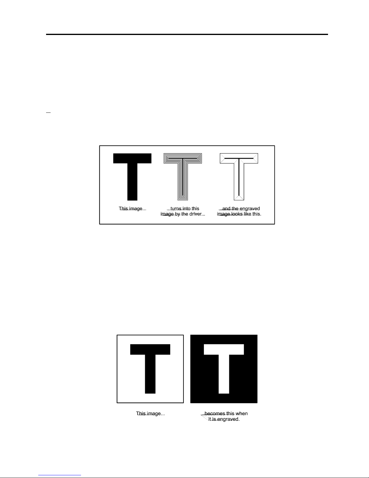
Use the letter “T” as an example. Pretend to create a “T” in your graphics program. Fill it with
black and make sure it does not have an outline. If the “3D Effects” option is activated and the
”T” is printed to the laser system, the driver turns the “T” into a three dimensional object that
has defined steps of laser power. The final image looks as if it is chiseled into the material.
Special
Choose “Add Shoulder” to activate the 3D Effects feature. This adds a shoulder to all raster
graphic objects within the engraving area but does not effect vectors
Print as a Negative Image
Inverts the entire page of graphics. Turns any white object into black and any black object into
white. Since this option creates a negative image for the ENTIRE PAGE, the raster engraved
object will be “raised” instead of “sunken” because the entire background will have been
engraved and the object will remain standing up. This is very useful for engraving a full sheet of
rubber stamps.
Page 36
The Printer Driver 3-11
Print as a Mirror Image
Mirrors the ENTIRE PAGE from left to right(horizontally). Will not mirror individual objects or
selections. Very useful for doing rubber stamps because the objects that are on screen are
readable, but when they engrave, they come out mirrored.
Shoulder
Choose from one of the preset options by clicking the down arrow in the “Shoulder Type”
dropdown list and selecting the type of shoulder you desire. These preset options are not
adjustable but you can create your own custom shoulder if you desire.
Add Custom Shoulder
This button allows you to create up to 10 of your own custom shoulders. First select a preset
shoulder option that most closely resembles the shoulder that you would like to start with, then
click on “Add Custom Shoulder”. You will see “Custom Shoulder #1” appear in the “Shoulder
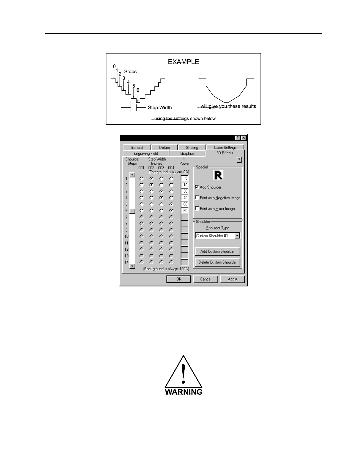
Type” dropdown list and the left side of the dialog box will enable. There are three adjustments,
the number of steps, the distance between steps, and the power setting for each step.
Before you set the parameters, you must first understand how each parameter works. In the
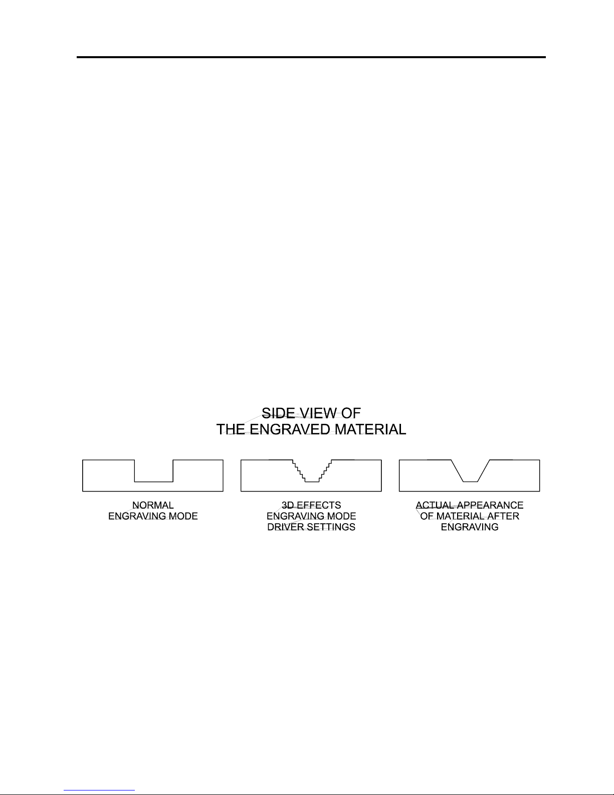
normal engraving mode, the laser beam engraves virtually straight down into the material. In
the 3D Effects mode, the laser beam is controlled in such a manner that it steps the power
settings in order to create a shouldered engraving.
From the diagram above, you can see that there were 7 steps used to create this shoulder.
The surface of the material is considered the first step and the bottom of the engraving is
considered the last step. Let’s use 7 steps as an example. You can define as many as 14
steps. The first or the last step are not definable because they are fixed at a power setting of
0% and 100% respectively. You can only define the parameters for the steps in between. By
adjusting the power setting for each step, the width in .001 inches for each step, and the
number of steps, different shoulder profiles can be created.
Page 37
3-12 The Printer Driver
The above settings are just an example to show you how to use the controls. This example
might not achieve the exact stated results on your particular material. This is why the driver has
custom settings available for you to control.
Delete Custom Shoulder
Click on the custom shoulder that you want to delete and then click on this button to
permanently delete it.
Deleted custom shoulder profiles cannot be restored so make sure that you absolutely want to
delete it before clicking on this button.
Page 38
4-1
SECTION 4
Graphics Software
Choosing the right graphics software program to run the laser system is essential for maximum
usage and control of the laser system. Not all software can be used to run the laser system
because many have limitations. Because you may be using a word processing software to
output to your laser printer does not mean you should use it to output to your laser engraving
system. Setting up you software correctly is essential to running the laser system properly.
Software Setup
There are many software programs that you can purchase off-the-shelf that will work with the
laser system. Some of them can access more features of the laser system than others.
Whichever program you choose, it must be set up to work with the laser system otherwise
unexpected results may occur. Use the following guidelines when configuring your software
program.
Page Setup
To properly generate and position artwork, most graphics software will permit the customization
of the page size and orientation. Set the page orientation, in the graphics software to
Landscape, and the page size to a horizontal length of 18 inches(457.2 mm) and vertical height
of 12 inches(304.8 mm). The drivers orientation and page size MUST then be set to match
these specifications EXACTLY, otherwise the artwork may not print correctly. When setting
page orientation and driver orientation to Landscape mode, the laser system will operate in the
horizontal direction, left to right. If page orientation and driver orientation is set to Portrait
mode, the laser system will operate in the vertical direction, front to back. The laser system is
designed to operate best in the Landscape mode and this orientation is highly recommended.
The page size may also be reduced to match the size of the engraving material, but remember
to adjust the page size in the driver to correspond to the graphics softwares page size. Note
that in production situations it is often more efficient to leave the page size at its maximum page
size and engrave or cut more than one object at a time. This is accomplished by duplicating the
image on screen as many times as necessary to fill up the entire page.
Ruler Setup
Usually the graphics software will provide on-screen rulers which can be configured to match
the rulers in the laser system. Using rulers in the software and matching them with the ones
provided in the laser system gives the ability to correctly align the graphic on the screen with the
material in the laser system. For now, consider that the laser systems origin is fixed in the
upper left corner of the engraving area and cannot be altered. Later on you will learn how to
relocate the origin. But for right now, change the ruler position on screen to match the laser
system with the origin (0,0) in the upper left corner.
Page 39
4-2 Graphics Software
It is also possible to use a page size smaller than the maximum engraving area. For example,
if an 8 inch(203.2 mm) x 10 inch(254 mm) page size is desired, set this page size in the
graphics software as well as in the driver. The laser system will automatically move the
engraving area to the origin so place the object all the way up into the left hand corner against
the rulers in the laser system.
Power Control Through Color Selection
The laser system allows the use of 8 different colors to access 8 different power settings when
cutting and engraving. This feature is controlled by the driver. When using this power change
feature with driver, the colors that are used MUST exactly match the colors listed in the driver.
The colors are black, red, green, yellow, blue, magenta, cyan, and orange. Some programs
will provide these basic colors pre-defined and other programs may require the creation of each
of the colors by defining them in CMYK percentages. If the eight driver colors are not
automatically provided in the software, use the chart below to create the eight driver colors by
specifying the appropriate CMYK values:
COLOR
CYAN
MAGENTA
YELLOW
BLACK
BLACK
0 %
0 %
0 %
100 %
RED
0 %
100 %
100 %
0 %
GREEN
100 %
0 %
100 %
0 %
YELLOW
0 %
0 %
100 %
0 %
BLUE
100 %
100 %
0 %
0 %
MAGENTA
0 %
100 %
0 %
0 %
CYAN
100 %
0 %
0 %
0 %
ORANGE
0 %
60 %
100 %
0 %
If using a color other than the exact colors listed above, the driver will attempt to match it to a
color in the driver that it most closely resembles. The driver will then use that colors power
setting and apply a halftone pattern to represent the original colors shade. For example, if
using a color like pink to fill a rectangle, the driver takes a reading of the percentage of different
colors used to create that color and will use the power setting assigned to one of the eight
colors of the driver that it most closely resembles. It might be expected that the driver will use
the power setting assigned to the color red but instead the driver may choose the magenta
setting and halftone the rectangle as a representation of the pink colors lighter shade. To
prevent the incorrect assignment of laser power, be sure to use the right colors. If using
graphics with colors other than the eight listed above or to simplify the assignment of power
settings, try using the Clipart Mode feature in the driver. This feature will cause the system to
only use the power setting assigned to the color black and halftone all of the other colors.
Outlines and Fills
The driver distinguishes between raster mode (engraving) and vector mode (cutting) by the type
of graphic artwork being used. Basically, all graphics other than outlines of very thin line widths
will be interpreted as engraved images and the raster mode will be used for output. If laser
cutting is desired, set the line thickness of the lines that are drawn in the graphics software to
.001 inches (.1 mm) or the smallest possible line thickness that is available.
Page 40

Graphics Software 4-3
The printer driver will interpret these objects as vectors and will cut them out providing that your
software has the capability of vector output. Basically, all software programs have the ability to
provide raster output. However, not all programs have the ability to provide vector output even
if you set the line width to the smallest thickness possible. Check with Software Anomalies
section in the back of this manual for software that can vector output.
The use of color fills or bitmaps will cause the laser system to engrave. The combination of
engraving and cutting is available in most graphics software. We suggest that when combining
engraving and cutting objects, use different colors for the fills and outlines since engraving
requires different power settings than cutting objects. One thing to keep in mind when creating
cutting objects is that if the outline thickness is set too thick, the driver might interpret the
outline as a filled object and will engrave the outline instead of cutting. This might be desirable
if engraving thick outlines is necessary. The outline thickness at which the driver will interpret
cut lines as filled objects is dependent on the software used. Usually, any line thickness .008
inches (.2 mm) or greater will engrave. The only way to determine the cross over point for line
thickness is to experiment with different line widths. Software programs that do not have outline
capabilities definitely will not have the ability to cut.
Image Processing Order
When cutting or engraving a graphic image, the laser system will perform all engraving first,
then proceed to cutting. Engraving will proceed in the exact order of the colors listed in the
driver. For example, all black filled objects will engrave first, then all red filled objects, then all
green filled objects and so on. When all engraved objects have been completed, the laser
system will proceed to cut any outlines present in the artwork. Unlike engraving, cutting will
proceed in the order from which the outlines are drawn regardless of color. There are several
different ways to control the order in which the outlines are cut. One way is to draw them in the
exact order in which they need to be cut, but this is not always practical. Another way is to
select the outline in the graphics software and “send it to the back”, behind the other objects, to
cause the outline to be cut first. Bringing the outline “to the front” will cause that outline to cut
last. A final way is to cut and paste each outline in the cutting order desired. This effectively
works the same way as the two previous suggestions.
Overlapping Fills
If the artwork created has overlapping filled areas, the driver will automatically filter these fills to
prevent the overlapped area from being engraved twice. This is similar to color separation in
the printing industry. The entire filled area of the object on top will be engraved and only the
visible part of the underlying filled area will be engraved. The final result is a what-you-see-iswhat-you-get output. In this way the color white can be used as an effective drawing tool.
Since the laser system will not engrave the color white (this is the background color), it can be
used to block out the undesired engraving areas of filled regions and/or bitmaps. However, you
cannot use a white fill to cover an outline, the outline will vector cut even though you cannot
see it on screen.
Page 41

4-4 Graphics Software
Overlapping Outlines
The driver does not filter outlines that overlap each other. If placing one outline one on top of
another, both outlines will be cut by the laser system. This is a useful feature that will allow
deeper cutting by passing the laser over a single outline path twice or more. To take advantage
of this feature, duplicate the outline on top of itself.
Hidden Vector Lines in Artwork
The driver does not automatically filter out outlines that are overlapped by engraved objects
such as fills. If there are filled objects with some hidden outlines underneath, the laser system
will then engrave out the fill and cut the hidden outline on top of the fill. This is a common
occurrence when using pre-drawn clipart designed for laser printers. To prevent this from
happening, turn on the Clipart Mode feature in the driver. This feature disables the cutting
mode and converts all visible outlines to engraved objects and ignores all hidden outlines.
Speed Optimizing
It is advantageous to engrave an object in its longest direction because total engraving time will
be reduced when the motion system has to make fewer stops and starts. If the engraving object
is longer than it is tall, a greater engraving speed can be achieved by rotating the graphic 90
degrees and placing the material in the laser system sideways. Be aware that some graphics
programs do not allow the rotation of bitmaps. In this case, it may be necessary to use bitmap
image processing software to first rotate the bitmap before importing the bitmap into the
graphics program. If the artwork contains engraved objects of the same color with a great deal
of space between them in the engraving direction, processing time can be longer since the
laser must make long strokes to engrave both objects at the same time. To reduce engraving
time in cases like these, use different colors for each of the objects but assign the same power
setting to both colors. This will cause the laser to engrave one object at a time, skipping over
all blank space, which in many cases will reduce engraving time. On the other hand, if the
objects are relatively close together in the engraving direction, then leave them the same color
because it will be quicker to engrave them both at the same time. Experiment with these
techniques to optimize the speed of engraving.
Bitmapped / Scanned Images
There are primarily three types of bitmaps available. They are monochrome(black and white),
grayscale, and color. Bitmaps are patterns of dots(pixels) blended to form pictures. Most
bitmaps are created by scanning artwork into a computer through a scanner. Others are
created by drawing them in a bitmap image processing program. The laser system can print all
three types of bitmaps providing that either the driver or the bitmap image processing program
converts the grayscale and/or color bitmaps into a monochrome bitmap. Essentially, the laser
system is a monochromatic printer, either it fires the beam to burn a dot or it does not fire the
beam to leave an empty dot on the material.
Page 42

Graphics Software 4-5
There are several different bitmap storage formats available: TIF, BMP, PCX, and others. We
prefer to use the TIFF format because it is most widely used format. The format makes no
difference to the laser system. The difference in formats involves how they are stored on your
computers hard disk. Bitmaps cannot be edited in most graphics software. Some basic
functions such as cropping, scaling, or mirroring might be possible but it is usually necessary
to use a bitmap image processing software to perform a dot by dot editing, rotation, or scaling
of the bitmap.
Monochrome Bitmaps
If you scan the image in monochrome(black and white) mode, set your scanner to at least 600
DPI. The higher the DPI, the smoother the image will be. Scanning monochrome images at
300 DPI is the minimum recommended resolution but scanning them at 600 DPI will provide a
significant improvement in the image quality. Clean it up in your bitmap image processing
program and save it to your hard disk. You can now either print the image directly from your
bitmap image processing program, or import the bitmap into a graphics program and print it
from there. Monochrome bitmaps are engraved in the same manner as black filled text. The
black area will turn the laser on and the white area turns the laser off.
Grayscale Bitmaps
When scanning image in the grayscale mode, you should scan the image at no more than 300
DPI. Scanning at a higher DPI does not improve image quality but it consumes more memory
and will take longer to print. Grayscale images cannot be printed directly to the laser system.
Since the laser system actually works like a black and white printer, grayscale images must be
converted into a black and white images. To do this, either the driver will do it automatically or
you can convert the grayscale image to a black and white image in your bitmap image
processing program.
The two primary grayscale image conversion techniques are Halftone or Error Diffusion. The
printer driver can print either one and it is selected in the driver under the “Graphics” tab.
Please refer to the section on the printer driver for more details on how to set these parameters.
Since the driver has a fixed method of conversion, you may want to experiment by using your
bitmap image processing program to make the conversion. These software programs usually
have more options for controlling the size, angle, shape, and the amount of black and white
dots(pixels) created when converting the image. Experiment with all of the controls to see
which looks the best. Big dots look good on some materials and small dots look better on
others. Once the image is converted by your program, save it and either print it directly from
that program or import it into your graphics program and print it from there. Essentially, a
Halftone image and a Error Diffusion image are actually both monochrome images and can be
treated as such. If you decide not convert the grayscale image to a monochrome image in your
bitmap image editing program, then the driver will do it automatically and will use settings
based on the Resolution settings in the driver. Again, refer to the driver controls section on
more details about how to use the driver.
Color Bitmaps
The driver handles color bitmaps the same as grayscale bitmaps. Since color bitmaps use
more memory, they are unnecessary and are therefore NOT recommended. You can scan
color photographs by using the grayscale mode or if it is already color, convert it to a
monochrome bitmap in your bitmap image processing program.
Page 43

4-6 Graphics Software
Encapsulated Postscript (EPS) Images
Bitmap images cannot be cut by the laser system only engraved. The only way to have the
laser system cut out or vector a bitmap is to first convert it to a vector file format such as an
EPS. Raster to vector conversion programs are available that trace the bitmap (this only works
well with monochrome bitmaps) and creates a separate EPS vector file. These EPS files can
then be imported into the graphics program and printed out from there. Since tracing programs
have many adjustments, some practice with them is necessary to produce desirable results.
The laser system does not support Encapsulated Post Script (EPS) printing directly. EPS files
can only be edited and printed if they are first imported into a graphics program. However,
since EPS files support engraving and cutting objects, they are therefore useful for transferring
artwork from one graphics program to another. Once an EPS file has been imported into a
graphics program, the objects can be outlined, stretched, rotated, mirrored, filled with
different colors, or anything else desired just as long as your graphics software can edit EPS
images. Be careful when using EPS files in layout software as opposed to true graphics
software. Layout software may allow the placement of EPS files in the artwork but may not
actually import and convert the EPS file to a useful format for the printer driver and therefore
may not print correctly. Please refer to your graphics softwares documentation on whether or
not it can edit and print EPS images to a non-Postscript printer.
Postscript (PS) Images
The laser system is NOT a postscript device. This means that postscript fills, postscript
textures, and especially POSTSCRIPT FONTS WILL NOT be able to print to the laser system.
Sometimes using Adobe Type Manager(ATM) will allow some postscript fonts to print correctly
but most of the time does not work properly.
Helpful Tip
If you are having any problems printing a font and you cannot figure out what is going on, select
the font and “convert to curves” or “convert to paths” in your graphics software. This will convert
the font into a bitmapped image and will print correctly to the laser system. Refer to your
graphics software on how to convert fonts. However, postscript textures and postscript fills
cannot be converted and will not print to the laser system.
Page 44
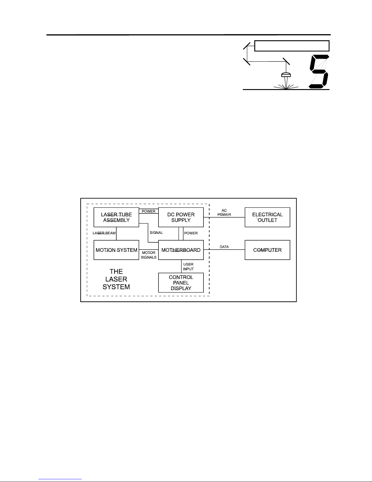
5-1
SECTION 5
System Operation
In this section you will learn how the laser system actually works and familiarize you with laser
system terminology. You will then start working with the control panel and learn how to get
around in the menu system. Since there are many features in this laser system, the menu
system may seem complicated at first, but once you start using it, you will find out that it is a
very simple system to operate.
How it Works
There are five (5) basic components that make up the laser system, the control panel, the
motherboard, the DC power supply, the laser tube assembly, and the motion system.
DC Power Supply
The DC power supply converts the incoming AC electricity to 48 volts DC. This is used to
power both the laser tube assembly and the motherboard.
Motherboard
The motherboard is the “brains” of the system and controls everything. Located on the
motherboard are standard computer memory SIMMS. This is where incoming files, from the
computer, are stored while the power is on. The motherboard gets input from the computer
and the control panel. It outputs precisely timed signals to fire the laser beam and to move the
motion system simultaneously.
Control Panel
This is where the operator controls the laser system. It is composed of tactile feel push buttons
and an LCD display. From this panel, the operator can position the motion system, move
around through the menu system in the LCD display, and run the laser system.
Page 45
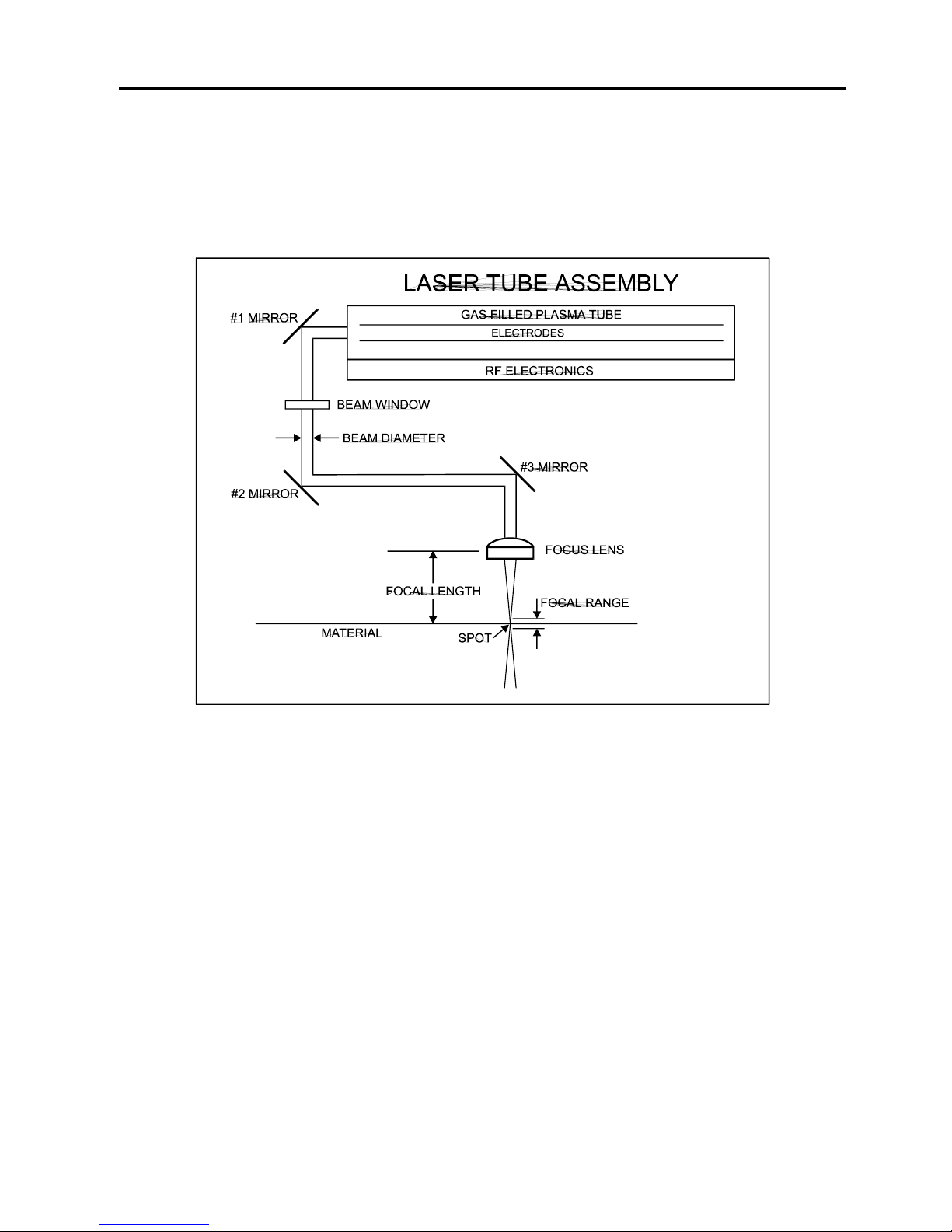
5-2 System Operation
Laser Tube Assembly
The laser tube assembly is a very sophisticated device. It is composed of a plasma tube filled
with a special mixture of CO2 and other gases, and RF (radio frequency) electronics. The
function of the entire assembly is to turn electrical energy into concentrated light energy. The
word LASER is an acronym for Light Amplified Stimulated Emission of Radiation.
The laser tube assembly It receives power from the 48VDC power supply and its “trigger signal”
from the motherboard. When the laser system is power on and the trigger signal comes from
the motherboard, the RF electronics produce a high frequency AC signal across the electrodes
located inside the plasma tube. This causes spontaneous photon emissions from the gas
mixture that produce an invisible, infrared light beam at a frequency of 10.6 microns.
The laser beam exits the laser tube through its output optics, bounces off the #1 mirror, passes
through the beam window, bounces off the #2 and #3 mirror, and finally passes through the
focus lens. The #2 and #3 mirror and the focusing lens are all mounted to the motion system.
The width of the laser beam as it exits the tube, called the “Beam Diameter”, is about 4 mm.
The focus lens focuses the beam into a very small spot whose “Spot Size” is dependent on the
“Focal Length” of the lens. The “Focal Length” is the distance from about the center of the lens
to the point where it converges the beam into the smallest spot possible. Using a standard 2
inch focal length lens, the spot size produced is approximately .005 inches.
The “Focal Range” of the lens, where the beam is considered to be “in focus”, is equivalent to
+/- 5% above and below the focus point. Shorter lenses produce a smaller spot size but also
have a very narrow focal range. This means that it would only be useful for engraving very flat
objects. The longer lenses have a much wider range of focus but also produce a larger spot
Page 46
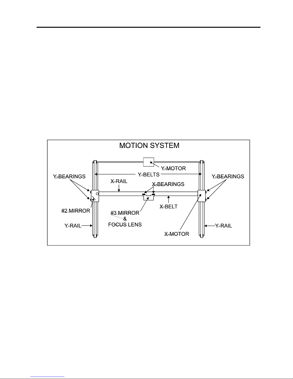
System Operation 5-3
size that would prohibit the engraving of fine detail. This can be related to trying to write small
text with a wide, felt tip marker. There are pros and cons to the different lenses that are
available for different applications. Please refer to the Appendices section on available lenses
and their operating characteristics.
“Wattage” signifies the amount of heat energy that the laser light is producing over a period of
time. Laser energy is measured with a laser power meter. Do not confuse the electrical
wattage rating of a light bulb or a hair dryer with the wattage rating of the laser system. They
are two different types of measurements.
Motion System
The motion system consists of the mechanically moving parts of the laser system. It is made up
of rails, motors, bearings, belts, mirrors, a lens, and other parts. There are two directions of
motion, left and right is called the “X” direction and front to back is called the “Y” direction.
The motherboard controls the movement of the motors which moves the mirrors and focus lens
across the engraving area and over the material. At the same time, it is synchronizing the laser
pulses with the position of the focus lens. It is this precise positioning and timing of the laser
pulses that produces the highest quality and fastest speed of engraving.
In summary, the five (5) components work together to take the graphic image that is
downloaded to the laser system from your computer and burn it into the material located on the
engraving table inside of the laser system.
Page 47
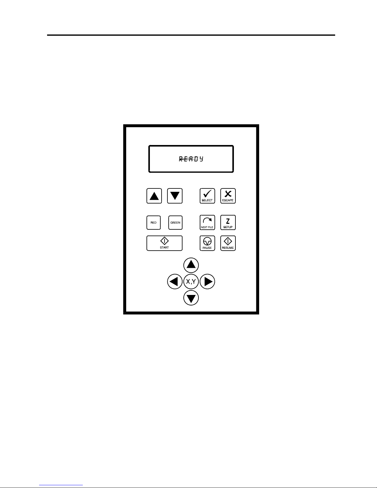
5-4 System Operation
The Control Panel
The control panel on the laser system provides easy access to all of the controls necessary for
cutting and engraving operations. The control panel consists of a liquid crystal display (LCD),
indicator lights, and selection buttons. The following section will describe, in detail, how to
maneuver through the menu system and the significance of each item in the control panel.
The Liquid Crystal Display (LCD)
The LCD is a four line display that displays the menus that control the laser system. It is a
backlit type of display that enhances visibility even under low light environments.
When the laser system is powered on, the laser system will perform a series of routines.
“INITIALIZING” will display until the motion system and electronics have finished their routines.
When completed, the display will then read “READY”, signifying that the laser system is ready
to accept files.
Page 48
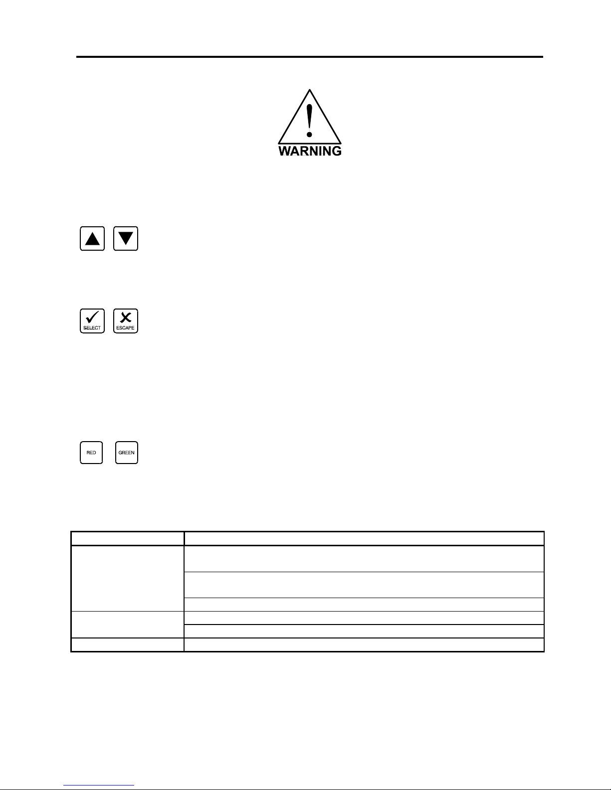
System Operation 5-5
DO NOT download files until the display reads “READY” as this can lead to an incorrect or
corrupted file download. Corrupted file downloads can lead to an incorrect firing of the laser
which can destroy the material you are engraving.
The two up and down arrow buttons to the left and below the LCD give complete access to the
menu control system. Use these arrow buttons to move the cursor up or down through the
items in the display.
Both of these buttons each serves two purposes. Depending on which menu you are in at the
time, the “SELECT” button either enters you into that menu item the cursor is currently on, or it
toggles that menu item to display different choices. Some items in the display lead to other
menus and some are settings that can be adjusted. The “ESCAPE” button, depending on
which menu you are in at the time, either exits you back to the previous menu or it nullifies or
cancels any changes that you have made to that menu item. Continuously pressing the
“ESCAPE” button will eventually bring you back to the “MAIN” menu.
The indicator lights will act differently depending on the current state of the laser system. The
chart below describes the conditions of the indicator lights during different modes of operation.
Green Indicator Light
CONDITION
REASON
ON
The laser system is powered up, the top door is closed and the system
is ready to receive a file
The laser system has finished processing a file and has returned to the
home position
The laser system has been paused while running a file
OFF
The top door is open
The laser system is firing the beam in the Alignment Mode
FLASHING
The file is running
Page 49
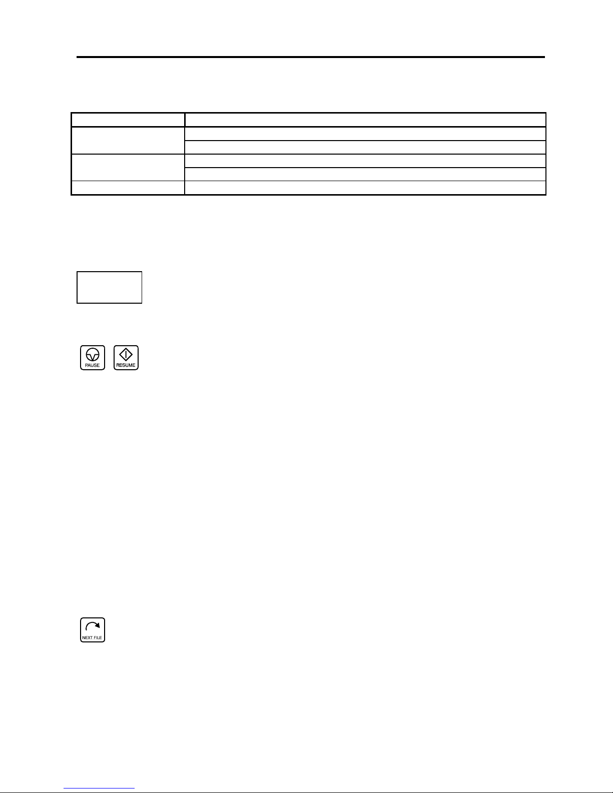
5-6 System Operation
Red Indicator Light
CONDITION
REASON
ON
The laser system is initializing
The laser system is firing the beam in the Alignment Mode
OFF
The laser system has finished initializing and is ready to receive a file
The top door is closed
FLASHING
The top door is open
The Process Controls
These control the actual running of the laser system.
Runs the current file displayed in the “File Display” menu.
If a job is running, the “PAUSE” button halts the engraving or cutting process. When paused,
the motion system arm will move to its home position in the upper right corner of the engraving
area. When ready to continue operation, press the “RESUME” button and the system will begin
cutting or engraving again exactly where it left off. If you wish to run the file from the beginning
after pressing the “PAUSE” button, press the “START” button.
NOTE: During slow raster or vector motions, the motion system might not pause immediately
after the “PAUSE” button is pressed. It can take a few seconds or maybe even several,
seconds to stop the system because it needs to complete the motion commands that it is
currently running. Opening the top door also works similar to the “PAUSE” button but not
exactly. The first thing that the laser system will do is turn off the laser beam immediately after
the door is opened. The next thing that it will do is pause the motion system. Since opening the
door and the pausing of the motion system are not precisely synchronized if you do this,
resuming the file might cause an area of missed engraving. Therefore, it is recommended to
use the “PAUSE” button instead of using the door to pause the system. Opening the door to
turn off the laser and to pause the motion system should only be used for safety or emergency
reasons.
Displays the next file in the systems memory and makes it the current file and will stop at the
last file in memory. This button is inoperative if a file is currently running.
The Motion Control System
The motion control section of the control panel (the four directional arrow buttons) enables the
user to manually control motion system movement.
Page 50
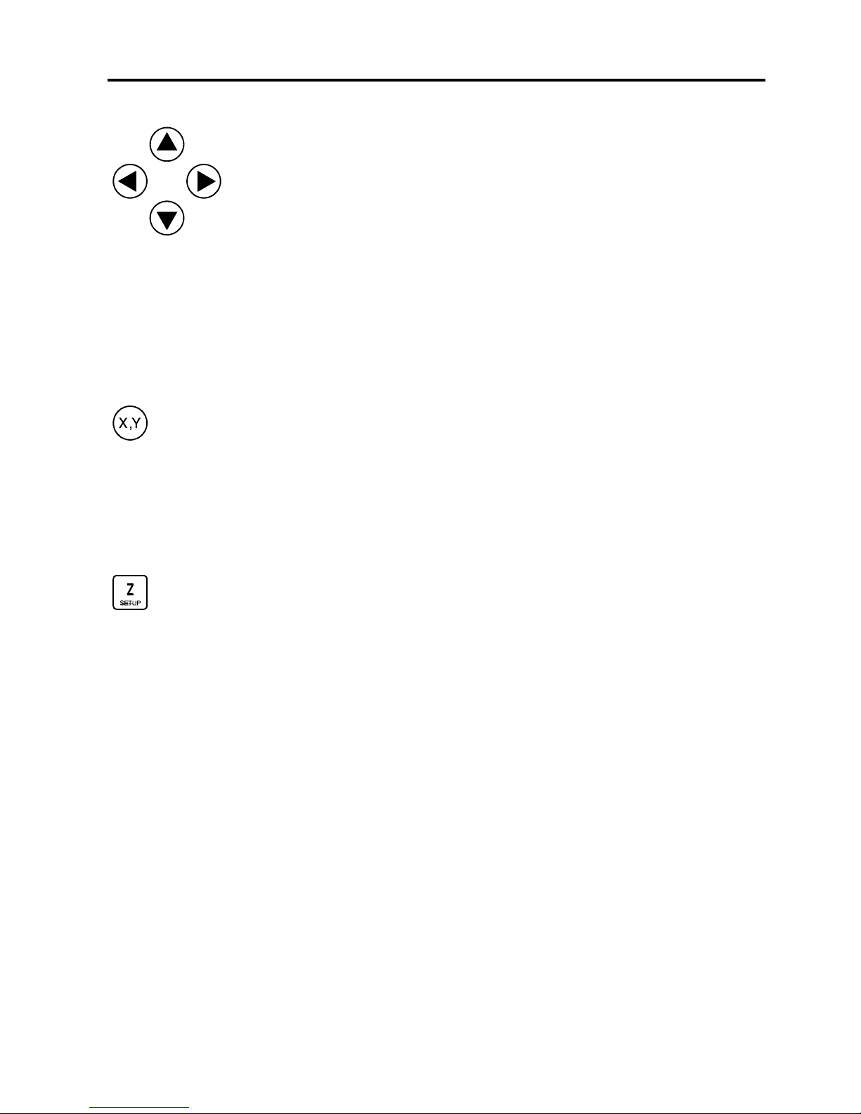
System Operation 5-7
Pressing and holding down an arrow button will cause the focus lens assembly to move in the
respective direction. The motion system starts off slowly, but if you continue to hold down the
button, you will see it accelerate to a faster speed. Pushing the button once and letting it go
quickly will move the motion system in .001 inch increments. Pressing two adjacent buttons will
move the assembly in a diagonal direction. This part of the control panel is primarily used to
position the focus lens assembly directly over the engraving material and to use the focus tool to
set the proper focus height. Other uses for these buttons will be discussed later in this manual.
You must be in the “FILE DISPLAY” menu or the “MAIN” menu for this button to be operable.
Pressing it enables the “ORIGIN POSITION” menu to appear. It also turns on the optional red
laser diode that shows where the focus lens assembly is positioned in the field by shining a
bright red “dot” on the engraving area. Further details on how to use this button will be covered
later in this section.
This button positions the focus carriage slightly away from the upper left hand corner at the
default (1,1) position in the engraving area. This is where the majority of focusing will be done.
Once the focus carriage is positioned, the motion system can still be moved by using the
motion control arrow buttons. Pressing the button again will move the focus carriage back to
the home position in the upper right corner of the engraving area. You can set the default
position to anywhere in the field that you desire. Relocating the focus position is covered later
on in this section.
The Menu System
The LCD displays the menus of the laser system. Since this laser system has many features,
we have included a “Menu System Flow Chart” on the next three pages. It diagrams and
displays the menu items in the entire system and the button selections needed to access them.
A description of each menu item follows the flow chart.
Page 51
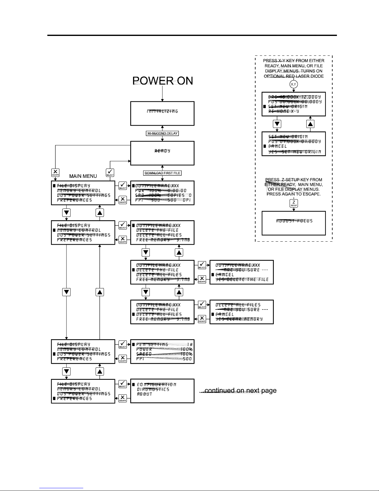
5-8 System Operation
Page 52
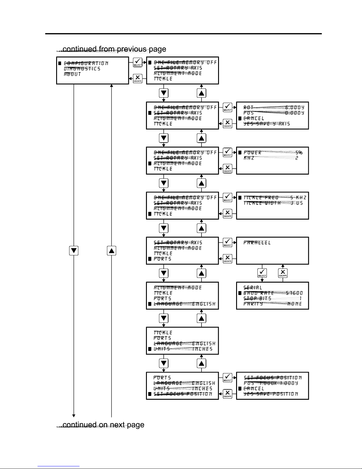
System Operation 5-9
Page 53
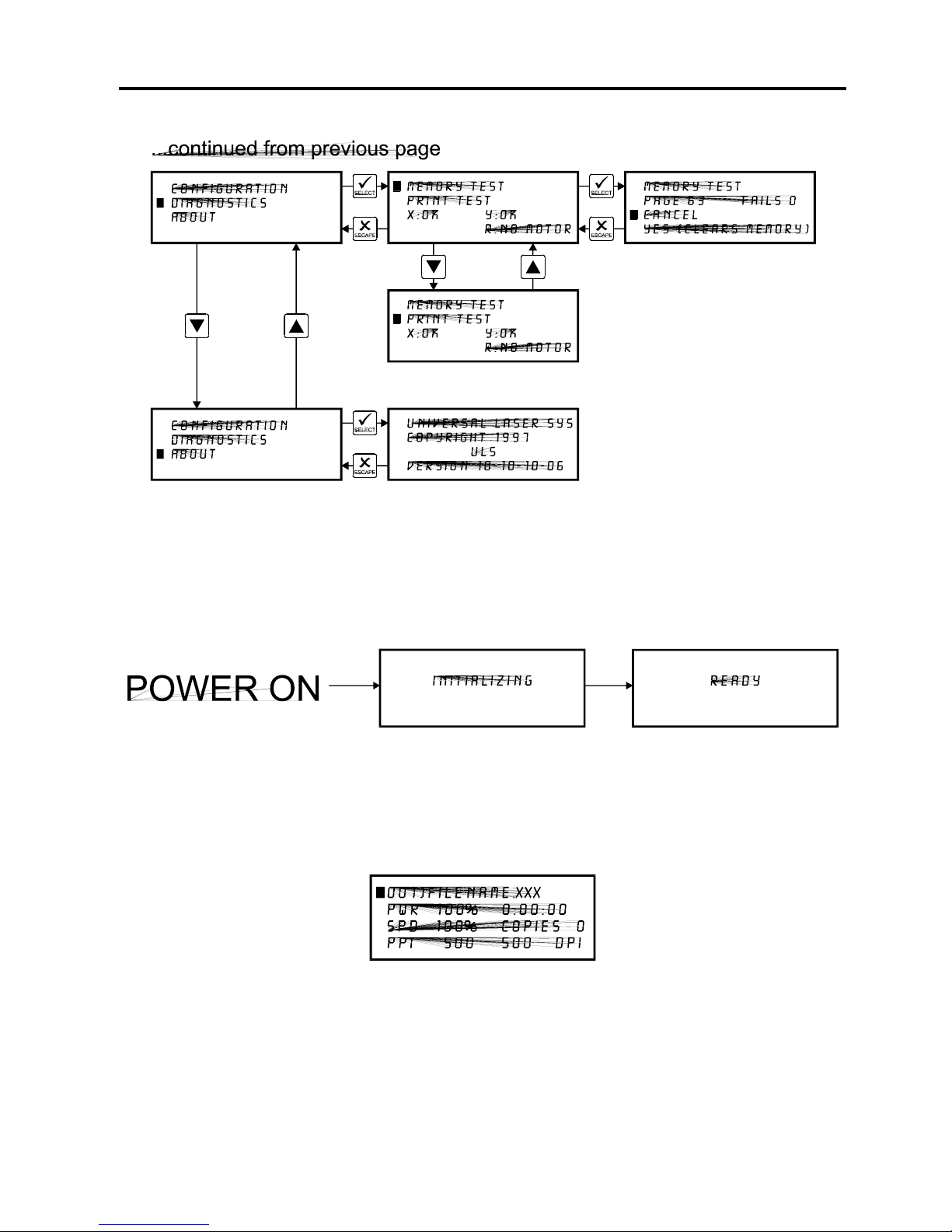
5-10 System Operation
Menu Descriptions
The remainder of this section will describe each one of the menus and their significance.
READY Menu
When the system is first powered on “INITIALIZING” will appear for approximately 30 seconds
until the laser system finishes performing its routine. When the system has finished initializing,
“READY” will appear in the display, indicating that the laser system is ready to accept files.
FILE DISPLAY Menu
Appears automatically after the first file is downloaded completely into the laser systems
memory. This is the menu that you will remain in most of the time when operating the laser
system. It has been designed to show all pertinent operating information at a glance so that
constantly jumping from menu to menu is not needed.
Page 54

System Operation 5-11
The first line indicates the filename. If more than one job has been downloaded, you can move
to the next file in memory by pressing the “NEXT FILE” button. You can page through the list of
files available in memory by placing the cursor on the first line of this display and pressing the
“SELECT” button which move the cursor to the right side of the display. The up and down arrow
buttons can then be used to move through the list of files in memory. When the desired file is
found, simply press the “SELECT” button to make that file the current file. This will move the
cursor back to the left side of the display. To run the currently selected file, simply press the
“START” button. Changing the current file is not possible while the laser system is running. For
experimental purposes, Power, Speed, and PPI settings can be altered while the file is running
allowing you to adjust these settings until the desired depth or effect is achieved. To do this,
press the up or down arrow button until the cursor is on the desired item. Press the “SELECT”
button which moves the cursor to the right and then use the arrow buttons to increase or
decrease the values. Pressing the “SELECT” button again will accept the change but pressing
the “ESCAPE” button nullify the change and restore it to the original setting. It is possible to
adjust the settings while engraving on some scrap material until the desired “POWER”,
“SPEED”, and “PPI” settings are obtained. Note these settings, change them in the driver and
re-send the file to the laser system for the final run.
NOTE: Since the file has the settings stored in the beginning of the data, you must first start
the file before you can change the settings. You can then either pause the file, change the
settings, and then resume the file or you can change the settings on the fly while it is running.
Remember, these are only temporary changes so if you pressed the “START” button to start
the file over again, it will take on the original settings that you sent down from the driver.
The display contains a timer to time files as they are run (this is useful for job costing). The
timer will pause when the “PAUSE” button is pressed and starts up again when cutting or
engraving has been “RESUME”d. If the same file is run again, the timer will count backwards
displaying how much time is remaining. The “COPIES” feature indicates the number of
completed runs of the file that is displayed. The DPI section displays the DPI setting from the
driver. The “TIMER”, “COPIES”, and “DPI” readouts are for display purposes only and cannot
be altered.
Since the laser system is equipped with a unique way of storing multiple jobs in memory,
special provisions are made to distinguish one job from the next. When using the printer driver,
an end-of-file(EOF) marker is automatically sent to the laser system after each file is
downloaded. An end-of-file marker is needed by the memory buffer in order for it to recognize
the end of one file, the beginning of the next file, and to calculate the remaining free memory
space. Without an EOF, the memory buffer will not operate properly.
There are two ways that a downloaded file will have a missing EOF. The first is if printing
through the printer driver and printing is canceled, interrupted, or file size exceeds the
remaining free memory space. If this occurs, chances are that the EOF never made it to the
memory buffer and the memory buffer will show that it is empty or that the file does not exist.
Part of the file might still remain in memory and might become mixed up with other files. This is
why having the ability to insert an EOF marker from the control panel of the laser system is very
important. In order to delete that partial file, the memory buffer must either be cleared entirely
or an EOF must be manually inserted into the memory buffer. Inserting an EOF is the better
choice here because the partial file can be deleted without disturbing the other files in memory.
Page 55
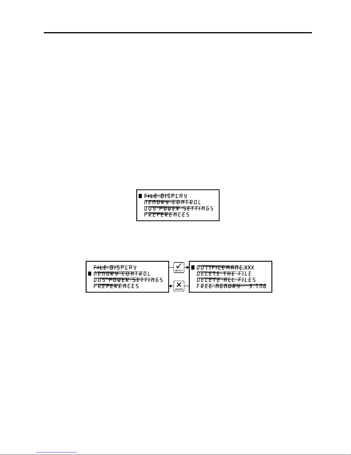
5-12 System Operation
Secondly, when using DOS based programs, a printer driver other than the Windows printer
driver must be used. DOS printer drivers do not know to send the required EOF to the laser
system after file downloading. Again, the memory buffer will not recognize any file that exists if
it does not have an EOF. In this case, an EOF must be manually entered into the memory
buffer after each and every file download from a DOS based program. Since DOS printer
drivers also do not send the name of the file within the file data, every file will be called
“NONAME” once an EOF marker has been inserted. To distinguish one “NONAME” file from
the next, the display will number the files in the order from which they were downloaded.
To insert an EOF marker in either case, position the cursor on the first line of the display where
the filename is. Press and hold down the “NEXT FILE” button and then press the “SELECT”
button at the same time. The word “NONAME” will appear if there is a partial file in memory or
any DOS based file that does not have an EOF marker. What has happened is that the laser
system searched for any file information that had entered into the memory buffer since the last
completed file was downloaded. If it finds information, it scans to the end of the last bit of that
information and inserts an EOF. The file then shows up on the display as “NONAME” and will
allow either its solitary deletion without having to delete the other files in memory or it will allow
the file to be run just as if it was downloaded from the Windows printer driver.
MAIN Menu
Allows access to all other menus.
MEMORY CONTROL Menu
The laser system is equipped with an intelligent memory buffer that has built-in file compression.
The driver actually compresses the file while it downloads to the laser system and the laser
system decompresses the file while it runs. The amount of compression can be as little as 4 to
1 or as great as 48 to 1. This means that with 4 MB of RAM in the laser system, the buffer
could hold the equivalent of 192MB worth of files provided they can be compressed 48 to 1.
This gives the laser system the ability to store either larger or more files in memory. It also
provides for quicker downloading because the files are much smaller than normal. The memory
buffer can hold up to 999 files providing that the memory space is not exceeded. The memory
also has built in file handling intelligence enabling each individual file in memory to be run in any
order. The files are stored sequentially based on the order in which they were sent from the
computer and each one is assigned a number to keep them in order. A running total of the free
memory space available is provided at the bottom of the display.
Page 56
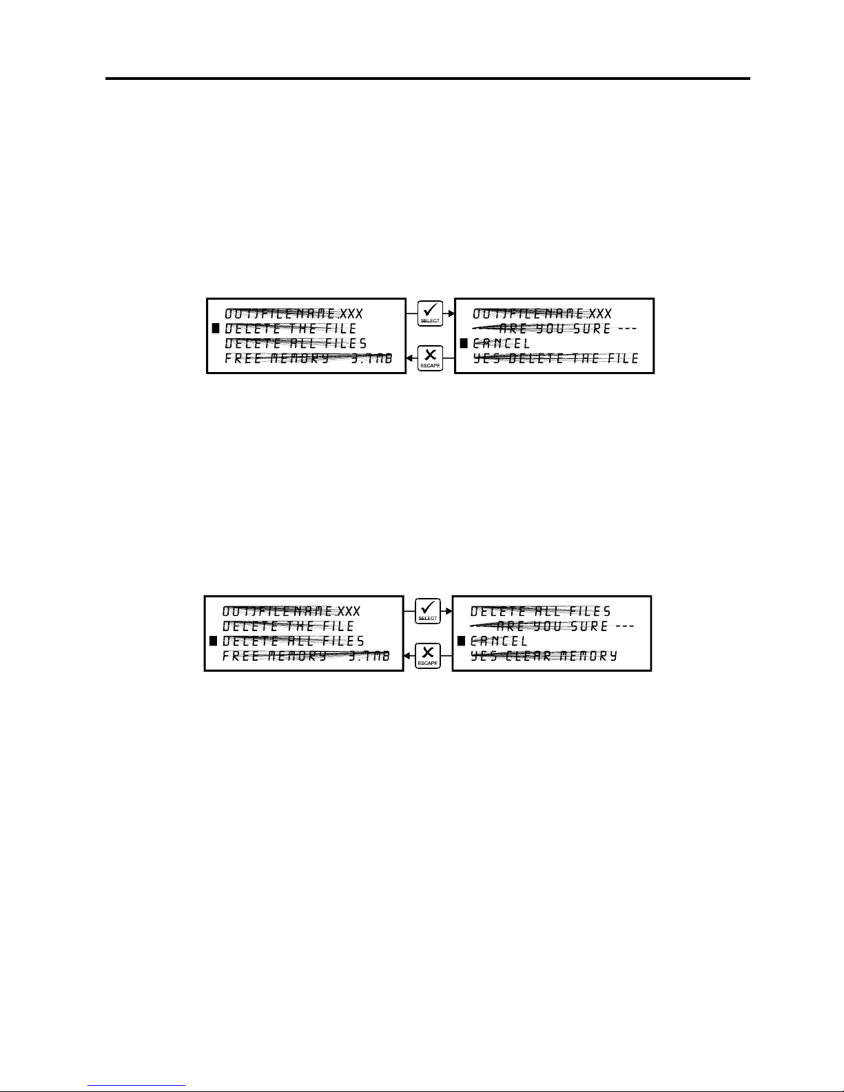
System Operation 5-13
The file name displayed is always the currently active file and there are two methods for looking
through the list of files to choose another one. The first method is to press the “NEXT FILE”
button on the control panel. Each time the “NEXT FILE” button is pressed, the next file in
memory becomes the current file. The second method is to move the screen cursor to the file
name line and press the “SELECT” button to move the cursor to the right side of the display.
Then, use the up and down arrow buttons to move backward or forward through the list until the
file desired is displayed. Now, press the “SELECT” button again to bring the cursor back over
to the left side of the display.
Eventually the memory will fill up with files that will need to be deleted to free up space for more
files. It is possible to select each individual file and delete them one at a time. To accomplish
this, make the desired file for deletion the current file in the same manner as previously
described. Use the up or down arrow buttons to position the cursor on the “DELETE THE FILE”
menu item and then press the “SELECT” button.
The display will then ask if you are sure and will expect a “CANCEL” or a “YES” response. Use
the up and down arrow keys to position the cursor on the appropriate choice and press the
“SELECT” button.
To completely clear out the entire memory buffer all at once, use the up and down arrow keys
to position the cursor on the “DELETE ALL FILES” option and press the “SELECT” button. The
laser system will again ask if you are sure so respond accordingly.
Deleted files cannot be undone. They must be re-downloaded if you accidentally delete them.
Page 57
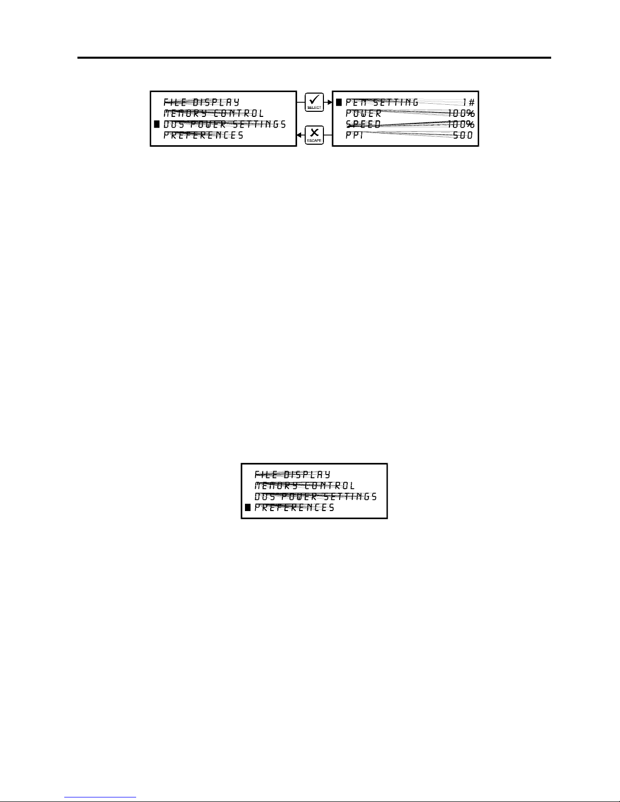
5-14 System Operation
DOS POWER SETTINGS Menu
The laser system allows eight different power settings to be saved, in non-volatile(permanent)
memory, and used when processing a DOS based file. Since DOS based printer/plotter drivers
do not have the ability to set the “POWER”, “SPEED”, and “PPI” settings, the settings must be
set manually on the laser system. Think of it as being able to assign laser “POWER”,
“SPEED”, and “PPI” to the pen numbers of a flatbed plotter.
To access these settings, move the cursor to the “DOS POWER SETTINGS” menu and press
the “SELECT” button. Press the “SELECT” button again to bring the cursor to the right side of
the display where it sits on top of the pen numbers. Now use the up and down arrow buttons to
scroll through settings 1 through 8. When the desired pen number is found, press the
“SELECT” button again to bring the cursor over to the left side of the display. Bring the cursor
down to the item you want to change, again press the “SELECT” button to bring the cursor to
the right and use the arrow keys to adjust your settings. Remember, to accept the setting that
you have made, press the “SELECT” button to bring the cursor back over to the left side of the
display. Pressing the “ESCAPE” button nullifies your change. Once you have set the correct
settings for all of the pen numbers that you will be using in your DOS software, press the
“ESCAPE” button to bring you back to the “MAIN” menu. Your settings will be permanently
stored just as long as you exit back to the “MAIN” menu before turning off the laser system. For
more information on how to use DOS based programs with the laser system, please refer to the
Appendices section in the back of this manual.
PREFERENCES Menu
The primary function of this menu is to allow access to other menus that can reconfigure the
laser system. It also allows access to diagnostic and maintenance features. Selecting this
option will lead to other menus of which some are adjustable and others that are display only.
Always escape back to the “MAIN” menu before turning off the laser system. This will
permanently store your changes in non-volatile memory. If you turn off the laser system without
escaping completely back to the “MAIN” menu then your changes would not have been stored
and the system will revert back to its previous settings.
Page 58
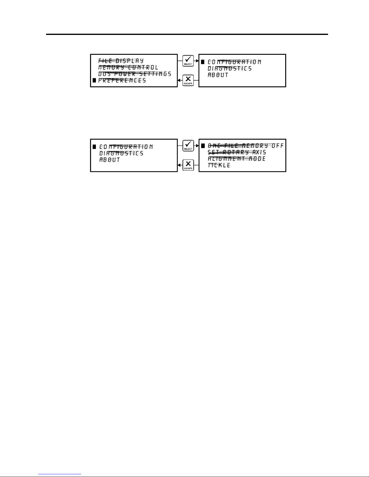
System Operation 5-15
CONFIGURATION Menu
Selecting this menu will allow the reconfiguration of certain features of the engraving system
and will lead to other menu items.
ONE FILE MEMORY Menu
Pressing “SELECT” key while cursor is on this line will toggle the setting on and off. When off,
it enables the multiple file memory buffer system (default). When on, it disables the multiple file
memory buffer and stores only one file at a time. How it works when it is turned on:
When you download a file to the laser system that file will appear in the “FILE DISPLAY” menu.
Press the “START” key and run the file just as you would as if you were in the multiple file
memory mode. You can run this file as many times as you want because it remains in memory.
Now, as you download the second file, observe the display and you will see “MEMORY
EMPTY” flash momentarily and then the new file appears. Basically what has happened it that
the laser system clears out the entire memory as the new file comes in to replace the first file.
You can now run that second file as many times as you want. If you download another file, it
dumps the entire memory again and the new file becomes the only file in memory, and so on.
While in this mode, the parallel port is turned off so no new files can be received until the file is
finished running. This is to prevent the incoming file from erasing the file that is running.
Helpful Hint
You will notice that while in this mode of operation, all files downloaded will be labeled as the
#1 file in memory. This might be confusing especially if you continuously download files with the
same name. If you do this, you might question yourself whether or not you downloaded the
next file because if you look on the display, it shows the same file number and the same name
as the previous file that you ran. But if you look further, the timer will show 0:00:00 and the
“COPIES” will be 0 if the file has never run. If the file did run, the “COPIES” will be greater than
0 and the time will show the amount of time that the file took to run.
Page 59
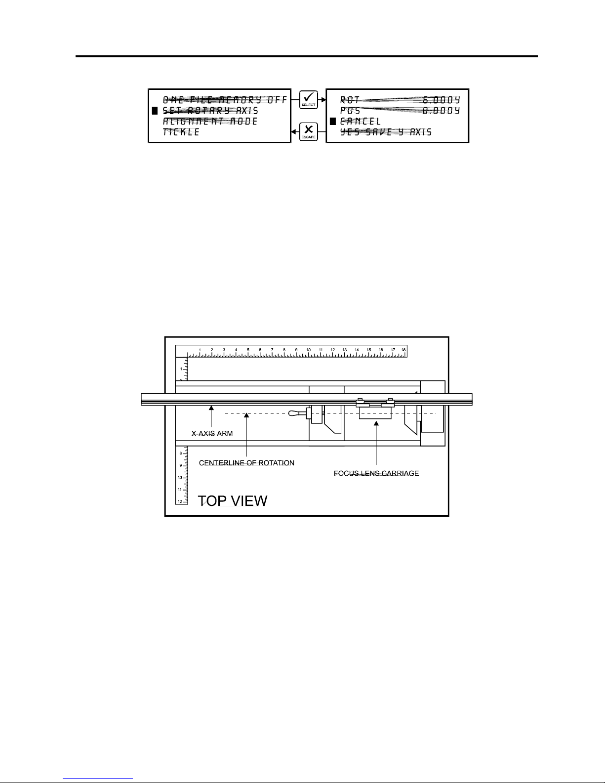
5-16 System Operation
SET ROTARY AXIS Menu
The Rotary Fixture Axis is a setting that is pre-set at the factory. The laser system will sense
when the Rotary Fixture is plugged in and will position the X-Axis arm directly over the
centerline of rotation automatically when it begins to engrave. This setting can be altered if you
position the Rotary Fixture in a location OTHER than the factory set position. Please refer to
the section on the optional Rotary Fixture for a full description on how to set up and use this
device before altering any factory setting.
To change the factory default setting, turn the laser system OFF, place the Rotary Fixture on
the engraving table in the desired position, and DO NOT plug the Rotary Fixture into the
electrical socket. Now turn the laser system on and with the motion system arrow buttons,
position the X-Axis arms focus lens carriage directly over the Rotary Fixtures centerline of
rotation as the following diagram illustrates:
The left and right position (X-position) of the focus carriage is irrelevant in this setting and is not
shown in the display. Now select the “YES SAVE Y AXIS” choice. If you change your mind and
do not wish to alter the “ROTARY AXIS” position, select “CANCEL” instead and the original
settings will be restored. Remember, always escape back to the “MAIN” menu before turning
the system off so that your settings will be permanently stored in memory.
If you would like to get the Rotary axis back to the original factory default setting, go back into
the “SET ROTARY AXIS” menu. While in this menu, press the up arrow and down arrow keys
simultaneously. The arm move will move back to its original factory default setting. Select
“YES SAVE Y-AXIS”, and then press the “ESCAPE” key twice to exit back to the “MAIN” menu
to store this setting permanently.
Page 60
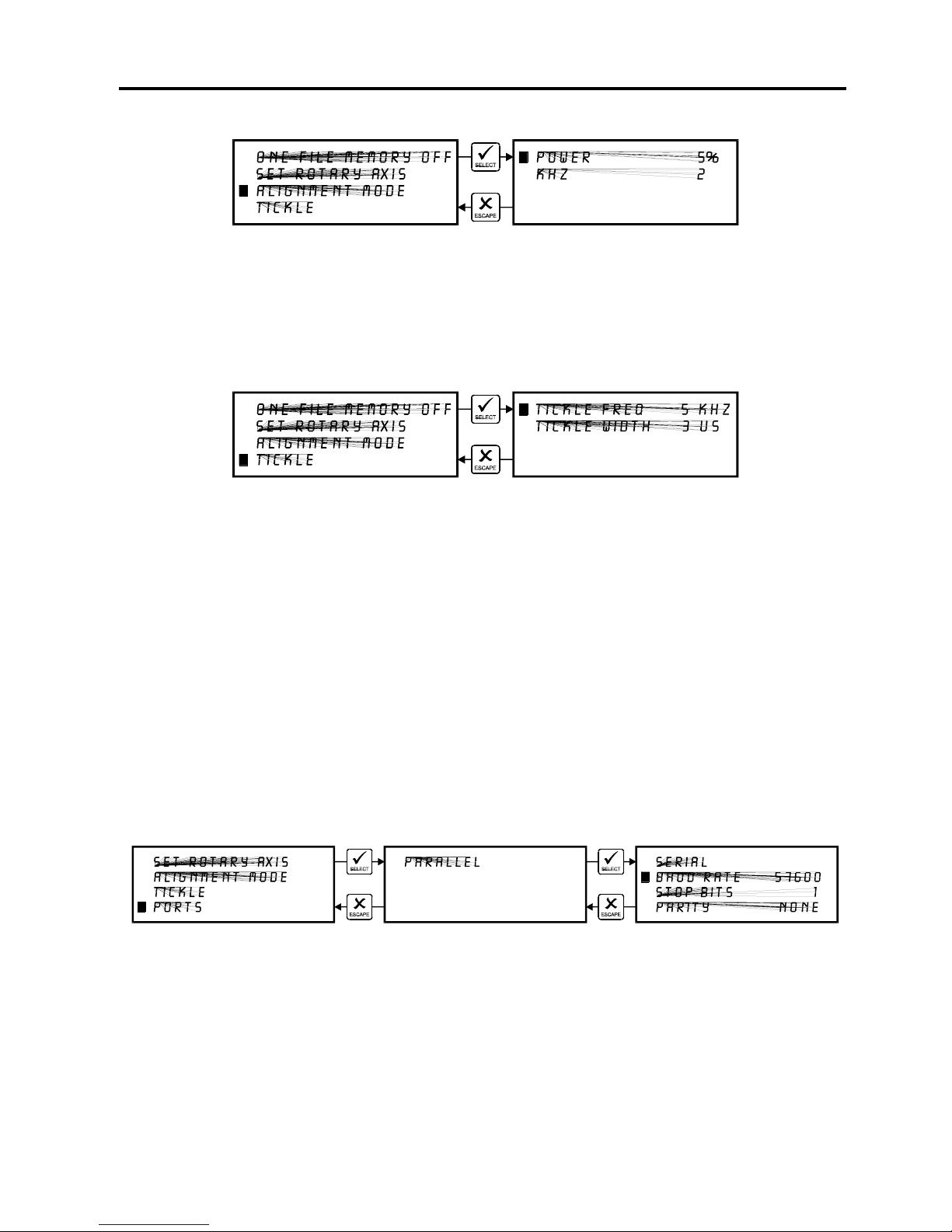
System Operation 5-17
ALIGNMENT MODE Menu
This menu allows access to firing the laser beam manually to determine if the laser systems
optical alignment is correct. The factory setting is a very low power setting that is just strong
enough to check the laser beam alignment. Please refer to the maintenance section on how to
safely check the laser systems beam alignment.
TICKLE Menu
TICKLE is the term used for small pulses, which are fed to the laser to keep the plasma inside
energized. This allows the laser to respond quickly and strongly for high speed cutting and
engraving. The setting shown above is only an example. Your laser’s setting may be different.
TICKLE keeps the laser "warmed up" at times when the laser system is powered on but not
firing and the top door is closed. We suggest keeping the door closed at all times when the
laser system is powered on as this keeps the laser warmed up. If the door is open, the power to
the laser tube itself is turned off and the tube will cool down. The laser runs best after being
warmed up for 15 to 20 minutes.
TICKLE is pre-set at the factory and usually does not require adjustment. However, it is
possible that it may need adjustment after the laser system ages several years. DO NOT
attempt to adjust the TICKLE setting. Please contact our Service Department for the correct
diagnosis and corrective procedure.
PORTS Menu
Two ports are provided on the back of the system for interface with a computer, a serial and a
parallel port. Only one port can be used at a time. To activate a port, use the up and down
arrow keys to position the cursor on the menu item “PORTS” and press the “SELECT” button.
The menu that appears indicates the currently active port on the laser system. To toggle
between ports press the “SELECT” button.
Page 61
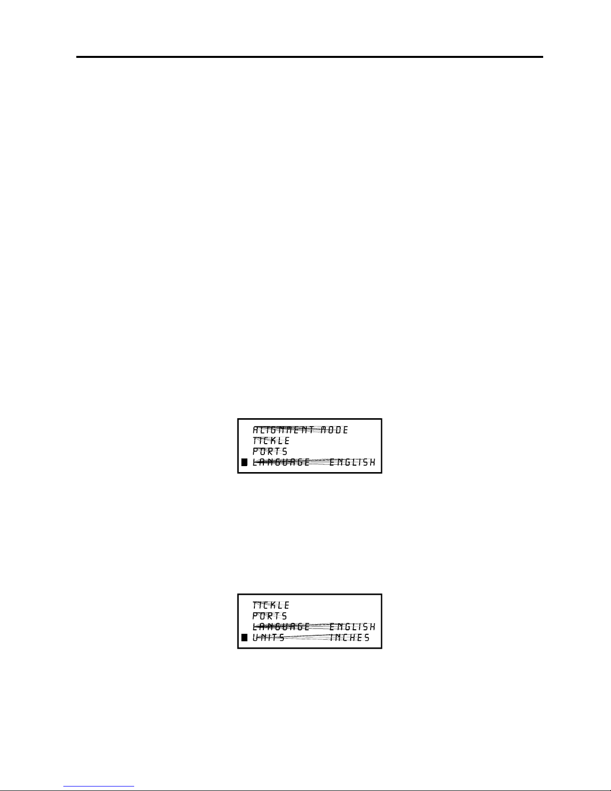
5-18 System Operation
In order to use the “SERIAL” port, the communication settings MUST match those of the
computer. Refer to the computers hardware and software manuals for details on setting up the
computers serial port. If using the “SERIAL” port, select the fastest possible “BAUD” rate for
communication since this effects how quickly the computer can send files to the laser system.
For “BAUD” rates of “9600” and above, set the number of “STOP BITS” on the computer to a
higher value than the number of “STOP BITS” selected on the laser system. For example if the
number of “STOP BITS” on the laser system is set to “1”, then set the computers stop bits to
“1.5” or “2”.
“PARITY” of the laser system and the computer MUST match exactly and the choices are
“ODD”, “EVEN”, or “NONE”. Pressing the “SELECT” button while the cursor is on “PARITY”
will toggle through these choices.
Helpful Hint
Since the serial port works much harder than the parallel port does, it uses much more of the
laser systems computer processors power to take in the files. Since this is the case, it is NOT
recommended that you download a file while the laser system is running a different file. This
can cause data corruption to occur to the file coming in to the computer. Either pause the laser
system or wait until it finishes engraving the file before downloading the next one. This situation
is for the serial port only. Disregard this warning message if you are using the parallel port for
communications.
The fastest method of file transmission to the laser system is the parallel port. Its use is highly
recommended.
LANGUAGE Menu
Use the “SELECT” button to toggle through many different language choices. When the desired
language is displayed, press the “ESCAPE” button twice to exit back to the “MAIN” menu. Your
settings will automatically be stored permanently in memory. When the cursor is on this menu
item, continuously pressing the “SELECT” button will toggle the languages in a loop fashion
and will always bring you back to the original language.
UNITS Menu
Use the “SELECT” button to toggle between “INCHES” and “METRIC” units. Once the desired
unit is displayed, press the “ESCAPE” key twice to exit back to the “MAIN” menu. Your settings
will automatically be retained permanently in memory. When the cursor is on this menu item,
continuously pressing the “SELECT” button will toggle the units in a loop fashion and will always
bring you back to the original units.
Page 62
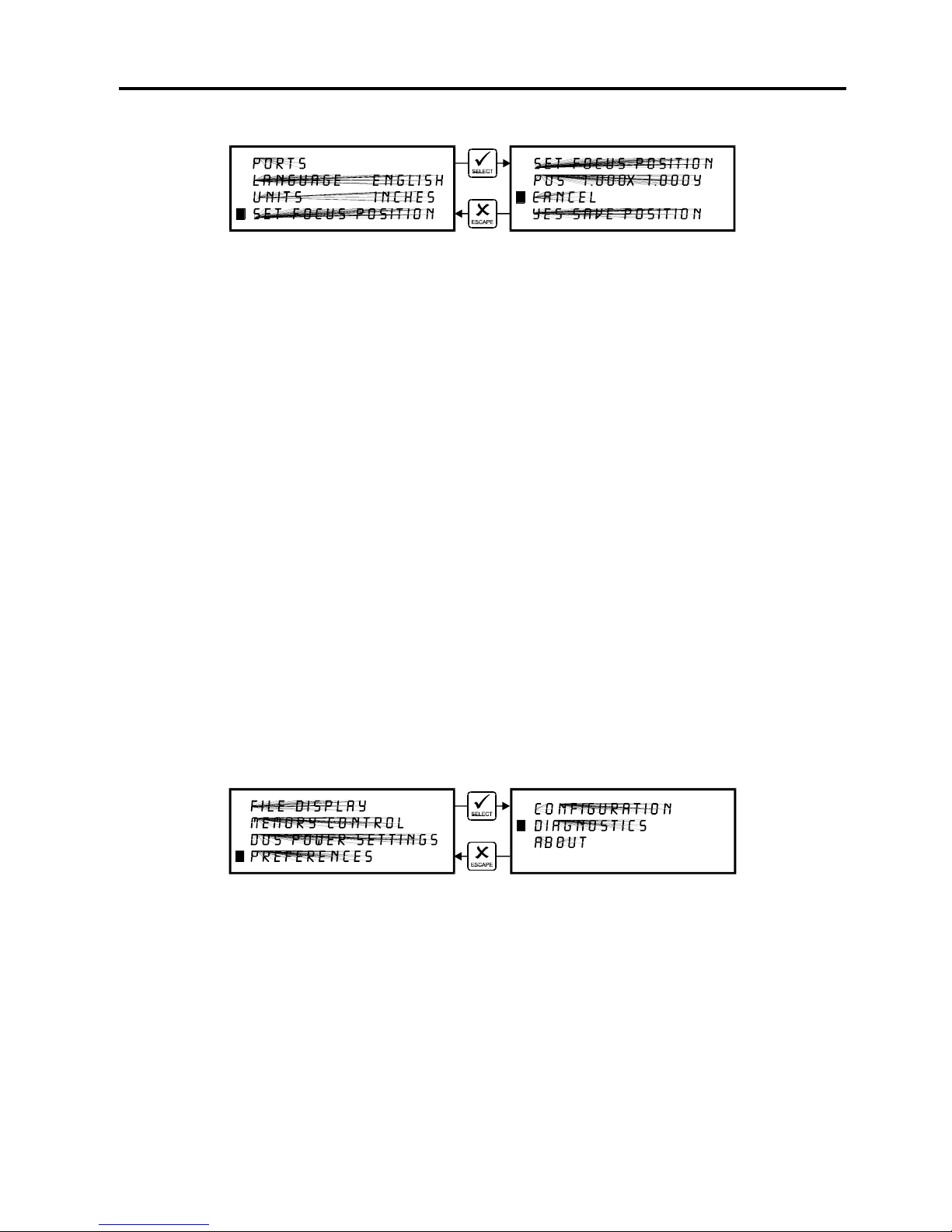
System Operation 5-19
SET FOCUS POSITION Menu
This option allows you to set the focus position to anywhere in the field that you desire.
Normally, the factory default setting for the “Z SETUP” button is (1,1). If you would like to
change the factory default setting, go to this menu and press the “SELECT” button. If you have
the optional red laser diode pointing device, the light will appear on the engraving table to assist
you in determining the position desired.
Using the motion control arrow buttons to position the focus carriage assembly. While you are
doing this can observe the coordinate display change as you move the focus carriage. These
coordinates are the current position of the focus assembly in the engraving field. Once the
desired position has been located, bring the cursor down to the “YES SAVE POSITION” line
and press the “SELECT” button. Press the “ESCAPE” button twice to exit back to the “MAIN”
menu. Your settings will automatically be retained permanently in memory.
To restore the focus position back to the original factory setting, go back into this menu and
press the up and down arrow keys simultaneously.
You will see the motion system move to the 1 inch horizontal and the 1 inch vertical position
(factory default). Now select “YES, SAVE POSITION”. Press the “ESCAPE” button twice to
exit back to the “MAIN” menu. Your settings will automatically be retained permanently in
memory.
DIAGNOSTICS Menu
This menu leads to two other menus that help diagnose possible problems with the laser
system. It contains a memory tester, a self-test print file, and a motor condition display. To get
into this menu starting from the “MAIN” menu, use the up and down arrow keys to place the
cursor on the “PREFERENCES” menu and press the “SELECT” button.
Page 63
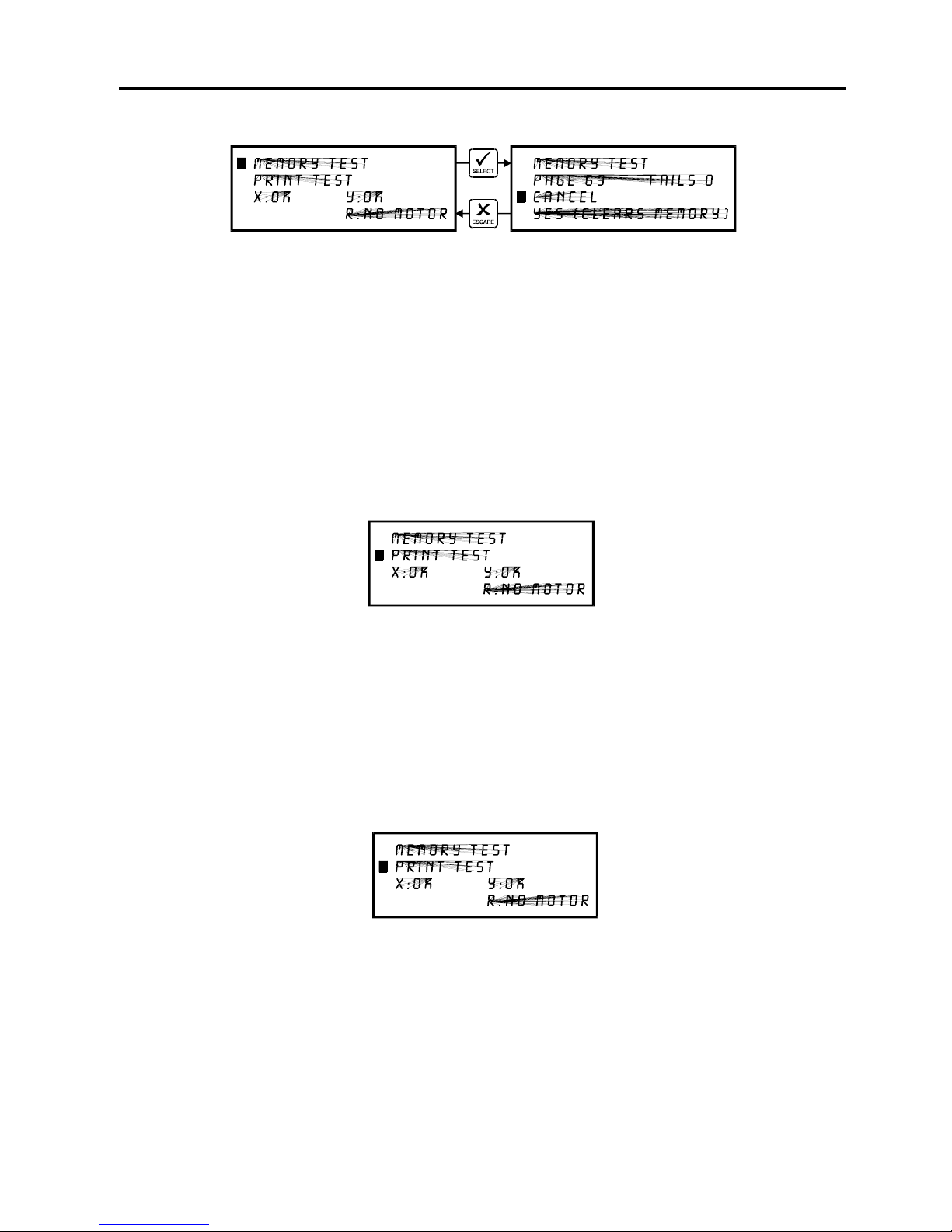
5-20 System Operation
MEMORY TEST Menu
It may be necessary to use the diagnostic tests if instructed to do so by a member of our
technical support staff. The “MEMORY TEST” is a memory buffer test to test the RAM in the
laser system. This is very similar to the RAM test that your computer performs when it first gets
powered on. In the process of testing memory, all files in memory will be erased. Once the
“MEMORY TEST” is started it will continue to run until it is canceled. To start the test select
“YES (CLEARS MEMORY)”. To end the test, select “CANCEL”. This test will continuously
pass through the memory.. If you are going to run this test, start it and let it run for about 10
minutes. If it finds memory that is bad, it will show up as a number other than a “0” in the fails
column and the SIMM module will need to be replaced. Please contact technical support if
there is a problem with the memory.
PRINT TEST Menu
There is a built in test file in the menu system. To access this file, use the up and down arrow
buttons to position the cursor on the “PRINT TEST” menu item and press the “SELECT” button.
The display will get replaced with the text “001) MEMORY EMPTY”. After a few seconds a test
file name will pop up in the display. Place a piece of scrap material in the upper left hand
corner, we recommend anodized aluminum, focus on the material, turn on the exhaust
system, and press the “START” button. A test pattern will now engrave into the material that
can help diagnose if there are any laser or mechanical problems with the system.
MOTOR CONDITION Display
The last two lines of this display show the conditions of the stepper motors in the motion
system. If there is a problem there will be an error message displayed next to the troubled
motor. If the motor is completely disconnected, “NO MOTOR” will show in the display.
Page 64
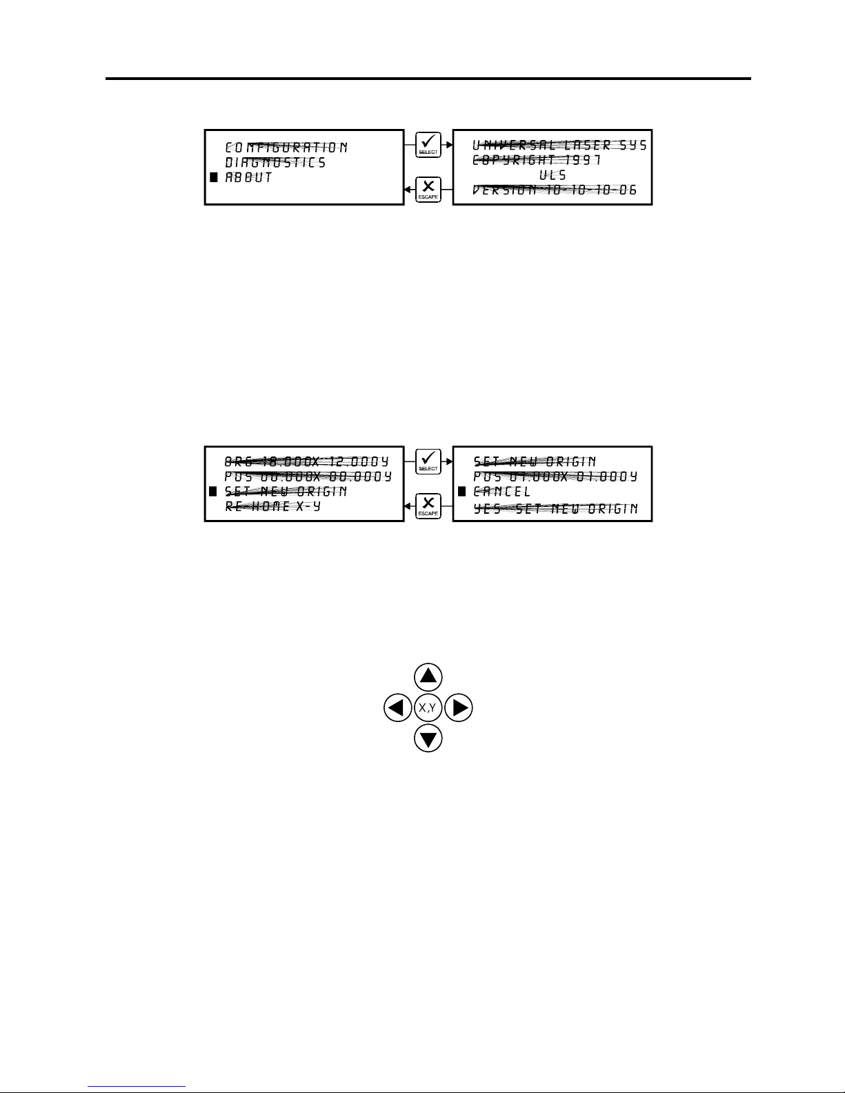
System Operation 5-21
ABOUT Menu
Use the up and down arrow buttons to position the cursor on this menu item. Press the
“SELECT” button and our copyright notice along with the current versions of firmware will be
displayed. The firmware version numbers are a diagnostic aid to our service technicians. If you
are having a problem with the laser system, a technician might ask you to read out the numbers
in this display.
To access the following menus, the cursor must be located either in the “MAIN” or the
“FILE DISPLAY” menus. They are not accessible if the cursor is in the “DOS POWER
SETTINGS” or the “PREFERENCES” menus.
ORIGIN POSITION Menu
The laser systems default origin position is in the upper left hand corner of the engraving area at
the (0,0) position of the rulers. You can, however, position the origin to any other point in the
engraving area. To do this you must first get into this menu. From either the “MAIN” menu or
the “FILE DISPLAY” menu, press the “X,Y” button in the middle of the four motion system
directional arrow buttons.
The red laser diode will appear on the engraving table. Using the directional arrow buttons,
position the red dot at the location you would like to store as the new origin position. If you tap
the motion control buttons, you will observe the motion system move at .001 inch increments.
The longer that you hold down the button, the faster it moves. You can use either the digital
display or the red dot as a reference for the new origin. When you have moved the red dot to
the correct position, bring the cursor down to the “SET NEW ORIGIN” menu item and press the
“SELECT” button. If you are sure with this position, move the cursor down to “YES, SET NEW
ORIGIN” and press “SELECT” again. Escape out of the menu and your settings will be saved
permanently in memory.
Page 65

5-22 System Operation
Setting a new origin other than the default (0,0) position will shrink your field size. If you already
have files already loaded into memory that utilize the entire engraving area, and you set a new
origin, part of that graphic might fall out of the effective printing area. If you run this file,
unexpected results can occur that might destroy your material in the engraving area. We
suggest that you use this feature cautiously and make sure that you do not set a new origin that
would cause you graphic to print off the engraving area.
If you would like to reset the origin back to the original factory settings of (0,0) in the upper left
corner, a quick way to get the motion system back to the upper left corner is to simply press the
up arrow and down arrow keys simultaneously while in this menu.
You will see the carriage move to the upper left hand corner automatically. Again, select “SET
NEW ORIGIN”, then select “YES, SET NEW ORIGIN” and your settings will automatically be
stored in memory permanently.
Focusing the Laser Beam
To properly focus the laser beam onto the surface of the material, you need to perform two
tasks. First position the focus carriage directly above the material and then use the focusing
tool to adjust the Z axis table level until the material is at the proper distance away from the
focus lens.
Place your material into the upper left corner of the engraving field against the rulers. From
either the “MAIN” or FILE DISPLAY” menus, press the “Z SETUP” button located on the control
panel.
You will observe the focus carriage move to a pre-set focusing position of (1,1). The display will
now read “ADJUST FOCUS” to remind you the you now need to adjust the Z axis table to the
proper focusing height.
Page 66
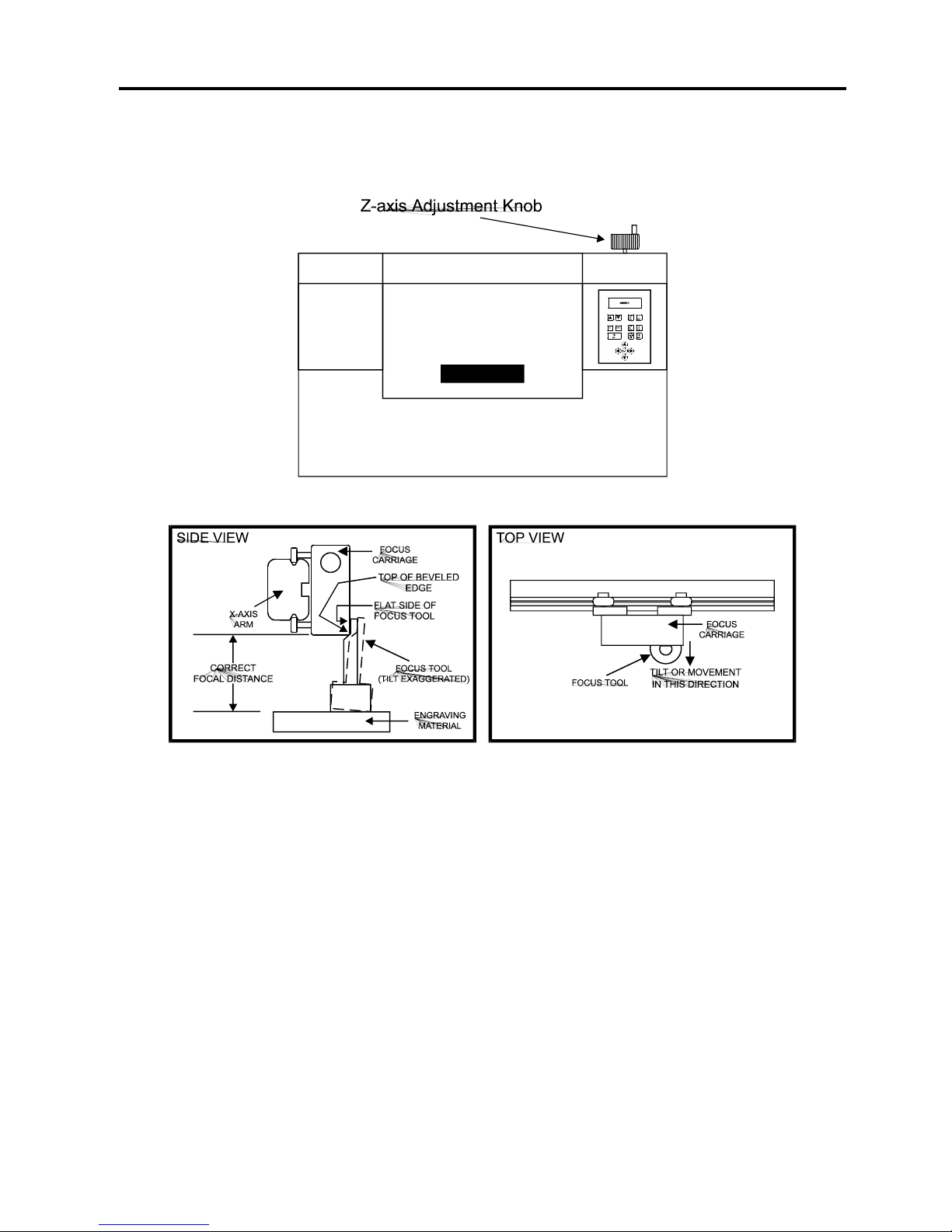
System Operation 5-23
Now, using the Z-axis adjustment knob, move the table either up or down so that the flat side
of the tool can sit flat up against the side of the focus carriage.
Slowly raise the table until you observe the tool either tilting or sliding away from the focus
carriage. This will occur when the bottom edge of the focus carriage meets with the top of the
beveled edge of the focus tool. The objective is to stop the table at the point where the tool just
starts to move or tilt.
Remove the focus tool and press the “Z SETUP” button to move the focus carriage back into the
home position.
If you find that you need to place your materials in a position other than the upper left hand
corner, you can change the default focus position to anywhere in the field that you like. Please
refer to that menu item selection earlier in this section.
You can also use the motion system directional arrow buttons to position the focus carriage
directly over your material. You do not need to press the “Z SETUP” button. Instead, hold
down one or two adjacent motion system directional arrow buttons until the focus carriage is
positioned over your material. Then use the Z axis adjustment knob and the focus tool to adjust
the material to the proper focus height. When finished, press the “PAUSE” button to move the
carriage back to the home position.
Page 67
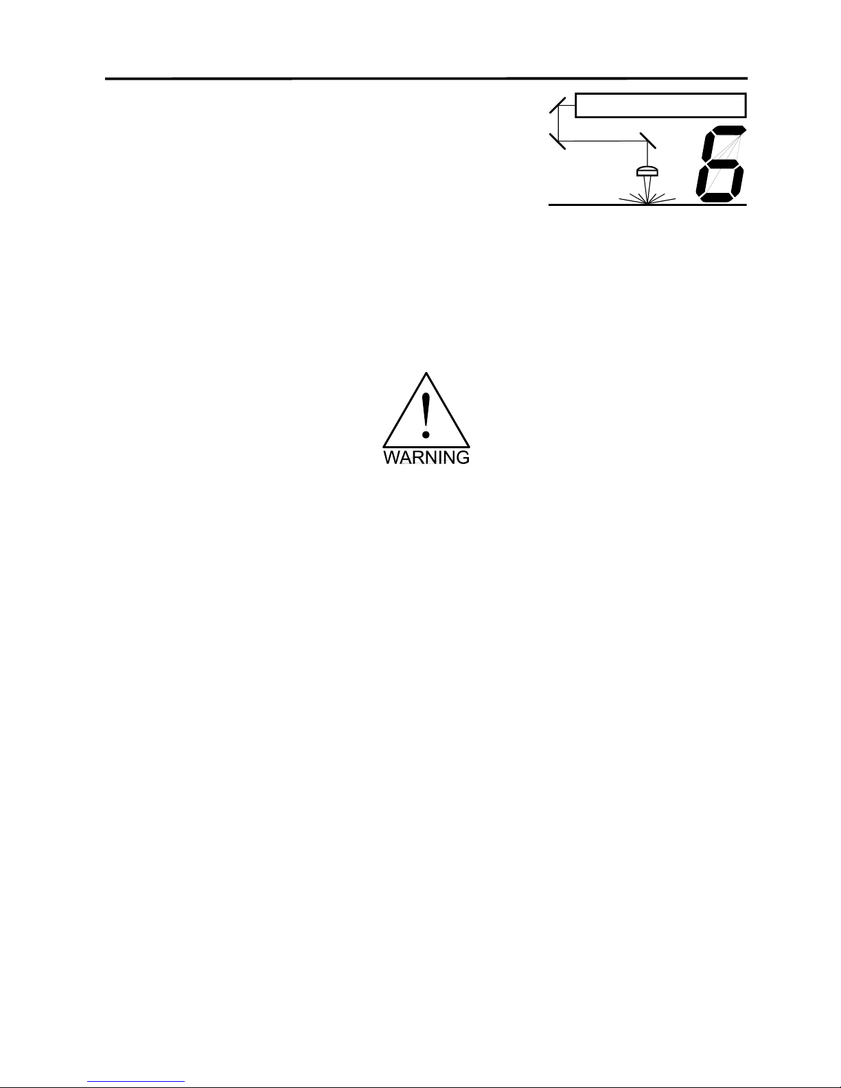
6-1
SECTION 6
Running the System
Step by Step
In this section we will cover how to completely use the laser system to create a product from
start to finish. From powering on everything to removing the finished product from the system,
we will cover the entire process step by step. As an example, let’s engrave and cut out a key
chain from a 2 by 4 inch, 1/8 inch thick piece of hardwood.
Before continuing, please ensure that you have completely read and understood the
entire manual up to this point. It is essential that you know how to safely operate the
laser system before you actually engrave or cut any material.
Powering Up
We recommend that you turn on your computer first and let it boot up completely before
powering up the laser system. This will prevent any garbage information that might have
traveled out the printer port from entering the laser system during power up. This common
practice should be utilized for all output devices whether it is a laser printer or a laser engraver.
If you happen to power up the laser system first and then power up your computer afterwards,
there is a possibility that some garbage information gets transmitted to the laser system. If you
then send down a file to print, that garbage may confuse the laser system and cause it to
engrave erroneously which could damage your material. This is why we recommend turning on
your computer first before the laser system as a safe practice. It is not necessary at this time to
turn on your exhaust system. We will do that later when we are ready to run the laser system.
Loading and Positioning the Material
The next step is to load and position the wood on top of the engraving table inside the laser
system. Open the top door and position the piece of wood into the upper left hand corner of the
table against the rulers as the diagram below indicates.
Page 68
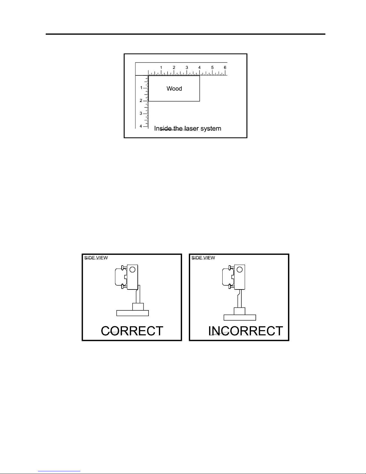
6-2 Running the System Step by Step
Focusing Methods
Before attempting to adjust the focal height, first make sure that the table is down low enough
to prevent the focus carriage from hitting into the piece of wood. To adjust the table height, use
the Z-axis adjustment knob. Turning the knob clockwise brings the table up and counterclockwise lowers it.
With the top door still open, press the “Z Setup” button on the control panel of the laser
system. You will see the focus carriage move to the (1,1) position directly over the piece of
wood. Using the focus tool adjust the table until the proper focal height is achieved.
WARNING: Be careful not to position the tool underneath the focus lens as this can
damage the lens if the table is driven up into it.
Sometimes it is desirable to be slightly out of focus when engraving or cutting. It widens the
beam at the surface of the material to soften the image or create a wider cut line. One complete
turn of the Z axis adjustment knob moves the table either up or down .066 inches.
Page 69
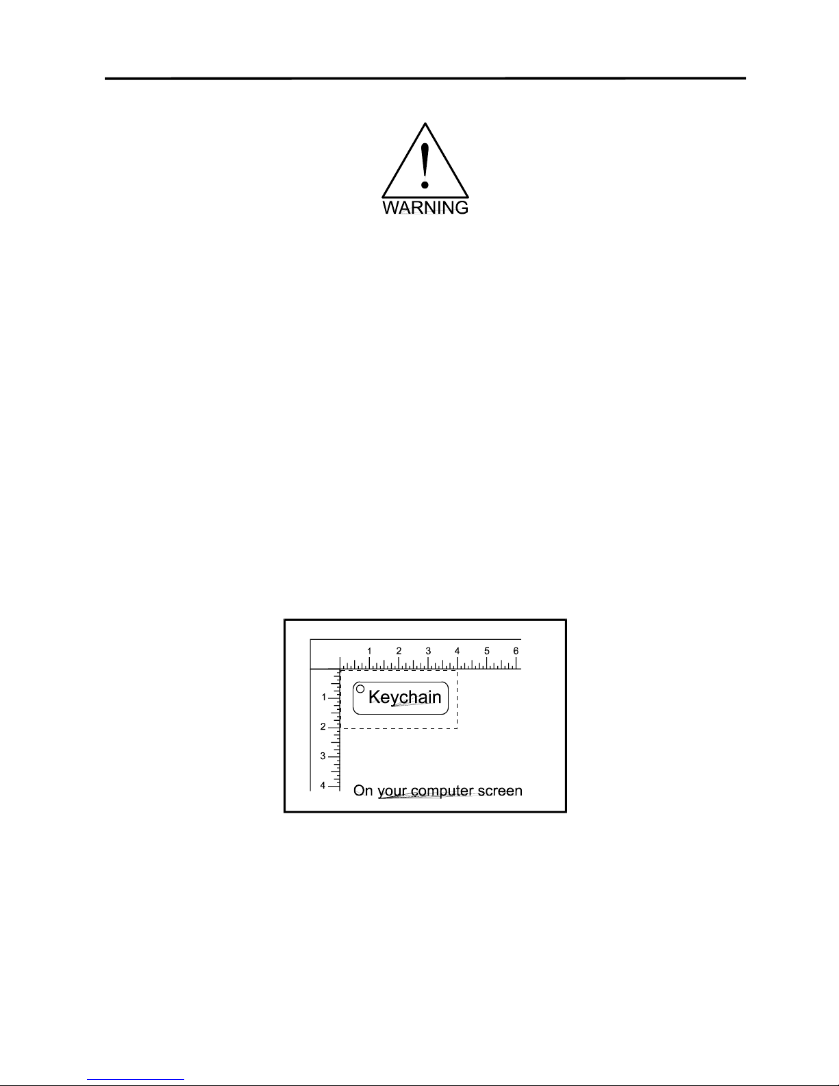
Running the System Step by Step 6-3
WARNING: DO NOT engrave or cut too far out of focus as this can be a potential fire
hazard. A maximum of two (2) complete turns of the Z-axis adjustment knob in either
direction from precise focus should be the limit.
It does not matter whether you bring the table up to go out of focus, or down, the effect is the
same. You should experiment on some scrap material at another time and note the difference.
In this example, we will engrave in precise focus. Once you have established focus, store your
focus tool and close the top door.
Creating the Graphic
In your graphics program set you page size to the maximum size of the engraving area, 18
inches wide by 12 inches tall in the Landscape mode. Create some text with a BLACK colored
fill and NO outline. For example, type in the word “Keychain”. Draw an outline box around the
text, color the outline RED, give the outline a thickness of .001 inches, remove the fill color(if
any), and round the edges if desired. Now add a circle with the same RED outline .001 inches
and NO fill, for the key ring. Place the graphic into the upper left corner of the page, on
screen, relative to how the piece of wood is positioned in the engraving area as the following
diagram illustrates:
Setting the Drivers Properties
The next step is to set the drivers properties. From within your graphics program, get to where
you can see the driver parameter screen. Usually, there is a menu item called “Print Setup” or
“Print Options” that allows access to the printer driver screen from your graphics software. For
specific instructions on how to access the printer driver from your graphics software, please
refer to your graphics software instruction manual or online help screens.
Page 70
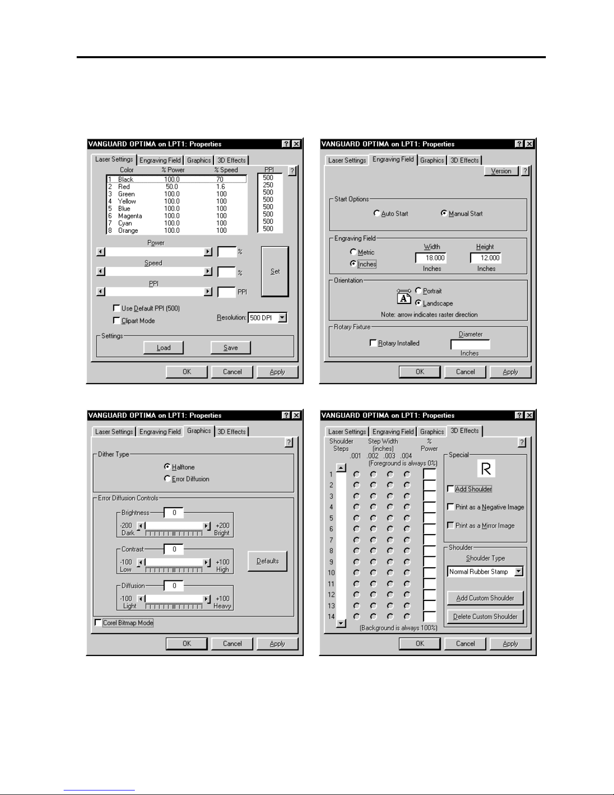
6-4 Running the System Step by Step
Once the printer driver is visible, click on the appropriate tabs and duplicate the drivers
properties as the diagrams below illustrate:
Page 71

Running the System Step by Step 6-5
Downloading the File
You are now ready to print to the laser system. Make sure the laser system is powered on and
the display reads “ READY”.
Find the “PRINT” command within your graphics program and click on it. Depending on which
graphics program you are using, the menu command “PRINT” may be in various locations
within your program. Usually after clicking on “PRINT”, you will then nee to click on “OK”.
A status screen may now appear showing a percentage of completion. Once this status screen
disappears, it does not mean that the file is totally in the laser systems memory. If you have
the Windows 95 print spooler turned on, it can take several seconds to even minutes,
depending on your file size and the speed of your computer, before the entire file loads into the
laser systems memory. Once the entire file is completely loaded, the display on the laser
system will automatically update and will display the files name and the power settings that you
assigned to the first color. One this appears, file download is now complete.
Starting the Engraving Process
Before pressing the “START” button on the control panel:
• Turn on your exhaust system.
• Make sure your material is positioned correctly within the engraving area.
• Make sure that you are properly focused.
• Make sure that the top door is closed and the RED light on the control panel is not flashing.
• Make sure the display shows the name of the file that you are going to run.
If all of the above has been verified, press the “START” button on the laser systems control
panel to begin the engraving process.
Observe that the laser system is functioning as desired. If any abnormalities are present,
including but not limited to, flaming, sparking, melting, or excessive smoking of the material
you are engraving, STOP THE ENGRAVING PROCESS IMMEDIATELY BY EITHER
PRESSING THE “PAUSE” BUTTON OR OPENING THE TOP DOOR! Re-check your settings
in the printer driver as well as the laser system. If everything seems to be correct, the material
is not suitable for laser engraving or cutting and you must abort processing this material or any
material that shows impending signs of damage to the equipment.
Page 72
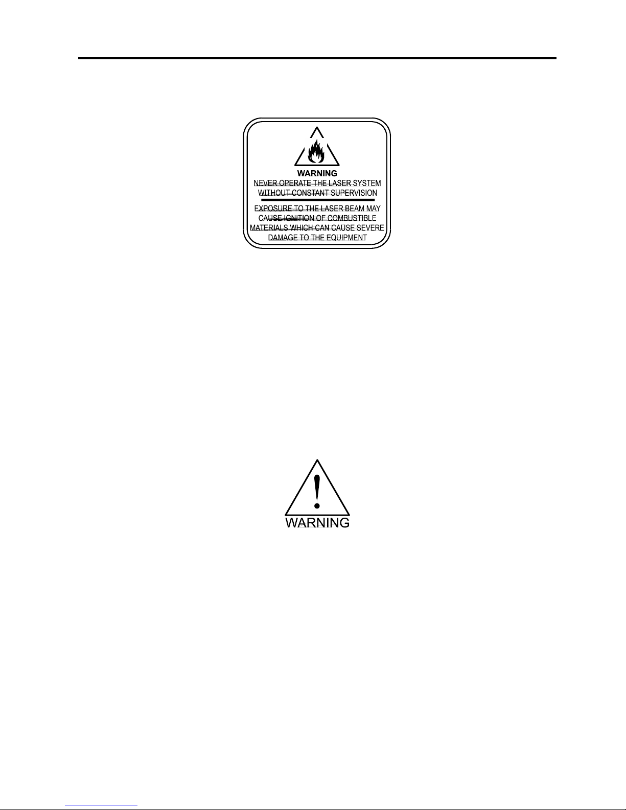
6-6 Running the System Step by Step
We will also remind you again to please follow the below warning label.
Material Removing and Reloading
Once the laser system has completed processing you material, the laser beam will turn off, the
motion system will move to its home position in the upper right hand corner, the system will
beep twice, and the green light on the control panel will glow continuously.
Before opening the top door, wait a few seconds to let any remaining fumes, that are leftover
from the engraving or cutting process, evacuate through the exhaust system.
Open the top door and remove your material. Some materials will continue to out gas for
several minutes to sometimes hours after the engraving or cutting process is completed. It is a
good idea to move these materials to a well ventilated area away from yourself and others.
Some materials, when engraved or cut with a laser, can produce toxic and caustic
fumes. We suggest that you obtain the Material Safety Data Sheet (MSDS) from the
materials manufacturer. The MSDS discloses all of the hazards when handling or
processing that material. The law requires all manufacturers to provide this information
to anyone who requests it. DISCONTINUE processing any material that shows signs of
chemical deterioration of the laser system. Systems damaged from this abuse will NOT
be covered under warranty.
While the top door is still open, load in your next piece of material. If it is the same as the
previous one and you want to run the file again, simply close the top door and press the
“START” button again to start the process from the beginning.
For further information on running the laser system in a different manner other than what has
been described in this section, please refer to the previous section on “SYSTEM OPERATION”.
Page 73
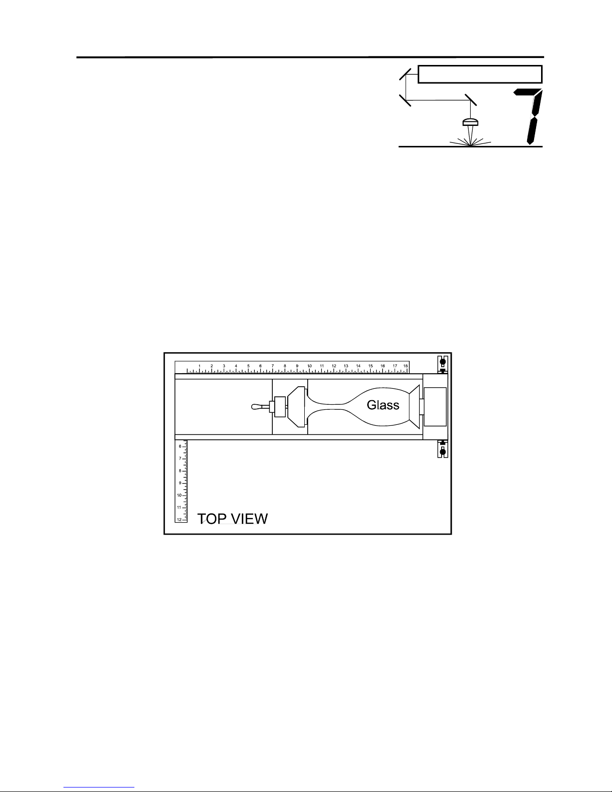
7-1
SECTION 7
Accessories
There are two accessories available for this laser system, the Rotary Fixture and 3D Effects.
The Rotary Fixture controls in the printer driver are used along with the optional Rotary Fixture
to engrave onto round or cylindrical objects. The 3D effects can be used to create rubber
stamps or produce a 3D effect on other materials.
Rotary Fixture
Two attachments come with the fixture, a cone shaped disk attached to the motorized end of
the fixture and an inverted cone shaped disk attached to the adjustable end of the fixture.
These attachments are designed to hold wine glasses, mugs, cups, etc. The Rotary Fixture is
placed on the engraving table as the following diagram illustrates:
For further details on how to operate the Rotary Fixture, please refer to the operating
instructions supplied with it.
Rubber Stamps
There are two method to create a rubber stamp, the single stamp method and the full sheet
method. In order to create a rubber stamp, the 3D effect feature of the printer driver must be
used.
We will show you the step by step method of creating both a single rubber stamp and a full
sheet of stamps.
Page 74
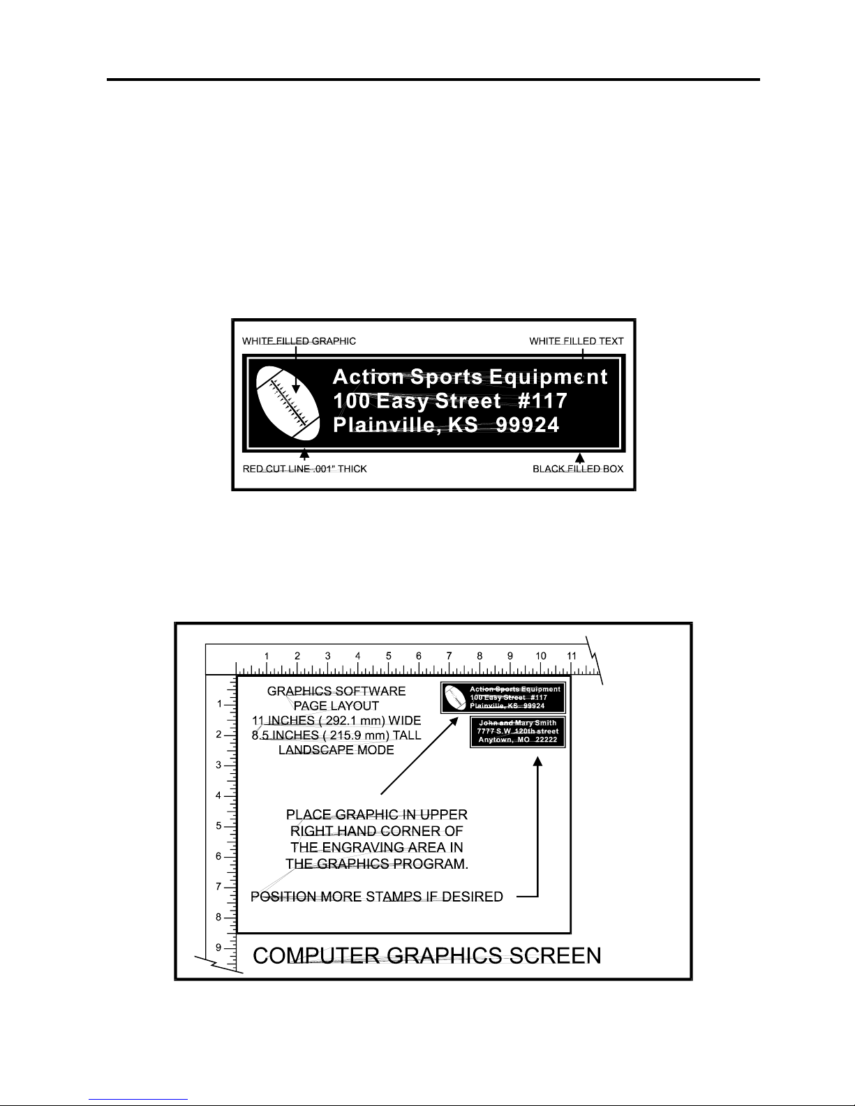
7-2 Accessories
Single Stamp Method
To create the artwork and engrave only one or a few stamps, set the page size in the graphics
program to something smaller than the full field. Just as an example, we will use a page size
that is 8.5 x 11 inches (215.9 x 292.1 mm) in the Landscape mode. In this way we can output to
a paper printer, before engraving, for proofreading. Make sure that this page size is set up the
same in the printer driver. Create a negative style stamp by drawing a black box slightly larger
than the size of the stamp desired. Type in or add graphics within that area and color them with
a fill of white. It is not necessary to mirror the image. Then draw a red outline box (.001 inch or
.1 mm line thickness) for the cut. There is no need to mirror the image, we will let the driver do
that later. An example is shown below.
Place the stamp in the upper right hand corner(on screen) if you want it to engrave in the upper
left hand corner inside the laser system. This is necessary because when the driver mirrors the
image, it mirrors the entire page along its centerline. It cannot mirror an individual object, only
the entire page.
Page 75
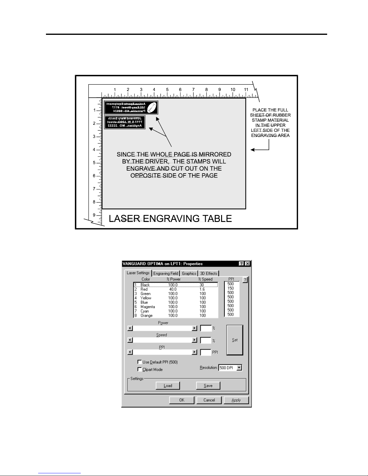
Accessories 7-3
Place the sheet of rubber into the upper left hand corner against the rulers, as the following
diagram illustrates, and be sure to properly focus on the material.
Set the printer driver properties as shown below.
These settings came from the section on Sample Materials. There is a considerable difference
between rubber blends, thickness, and hardness between different manufacturers. Experiment
with different settings to obtain the desired results.
Page 76
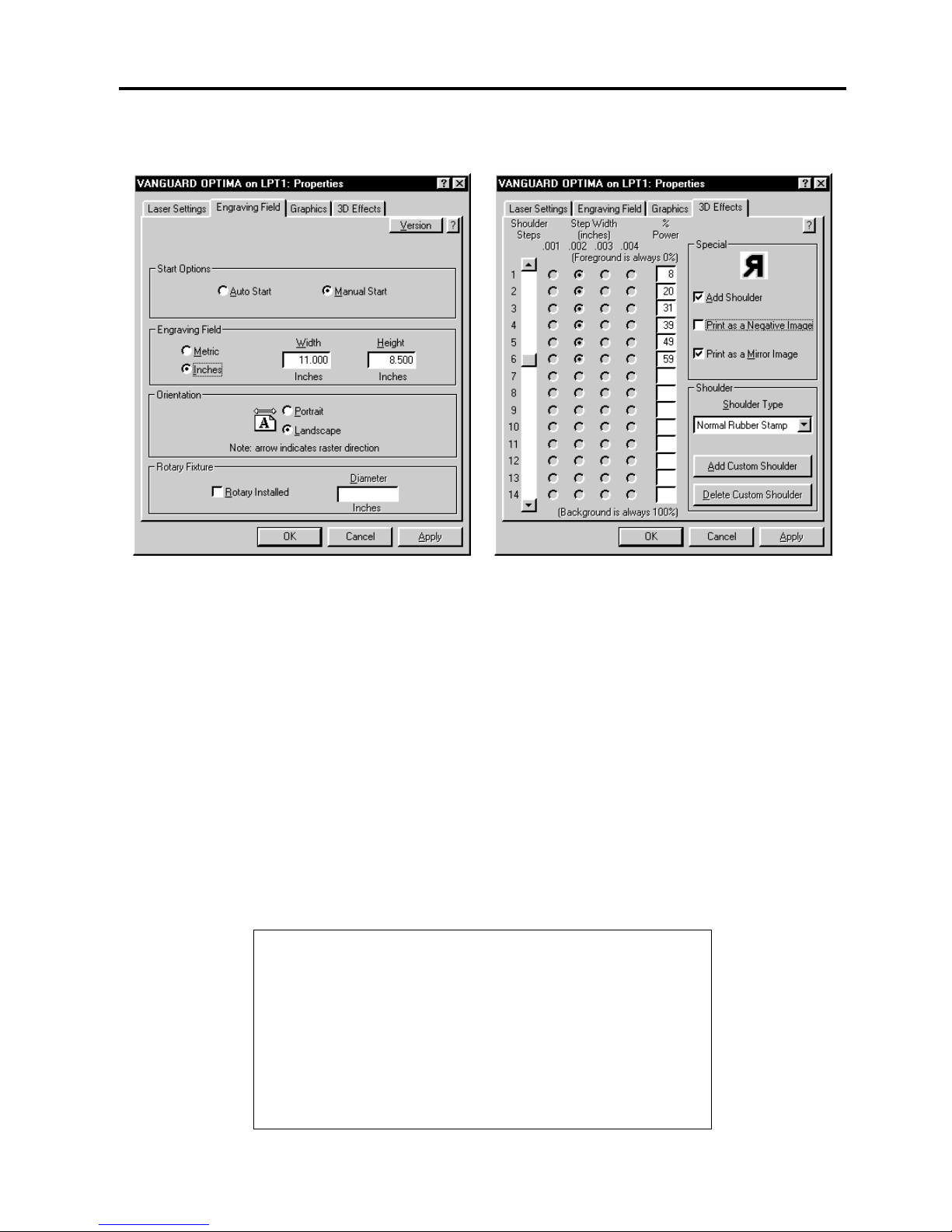
7-4 Accessories
Also set the following in the printer driver.
As you can see, we set the page size in the driver equal to the graphics programs page size.
We also selected "ADD SHOULDER”, “NORMAL RUBBER STAMP”, and “PRINT AS MIRROR
IMAGE”. We did not choose “PRINT AS NEGATIVE IMAGE” because this switch is only used
when printing a full sheet of stamps. For more details on how to use and set the other shoulder
types for the “3D EFFECTS” option, please refer to Section 3 on Driver Controls.
After making all driver selections, print the graphic to the laser system. Start engraving and
notice that the stamps are being engraved as a mirrored image and are in the correct position
on the rubber sheet. The background area, since it is colored black is being engraved and the
letters remain standing up. When the engraving part is done, the stamp gets cut out along the
red cut line due to the higher power setting that was assigned in the driver for the color red.
Full Sheet Method
The second method is to create a full sheet of rubber stamps and engrave them all at the same
time. First create a stamp as a positive image as shown below. Create more stamps to fill the
entire page. They can be the same stamp or different ones.
Page 77
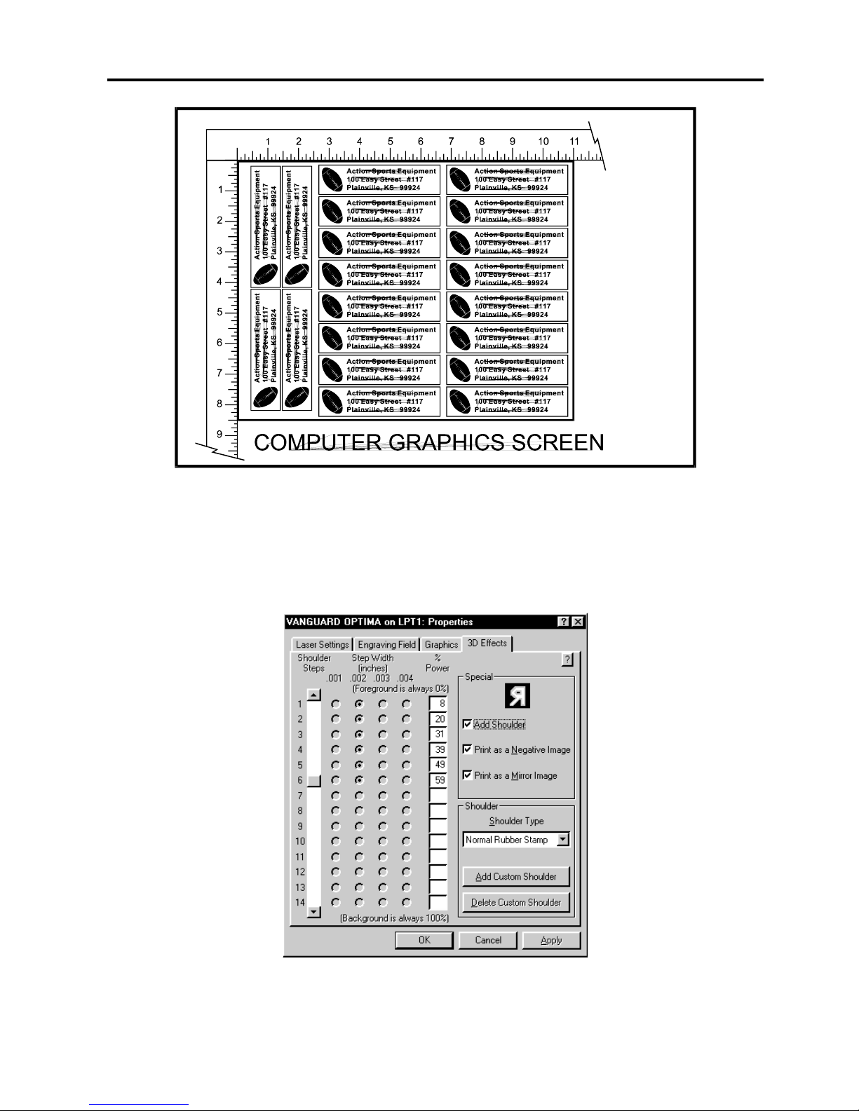
Accessories 7-5
If desired, output the page to a paper printer for proofreading. Printing out a positive image to a
printer is easier to read and uses less toner or ink than a negative print.
In the laser systems printer driver, use the same settings as the previous example but with only
one modification. In the “3D EFFECTS” tab, select the “PRINT AS A NEGATIVE IMAGE”
option as the diagram below illustrates.
Print to the laser system. Position the full sheet of rubber stamp material in the same upper left
location on the engraving table and begin engraving. The driver automatically adds the
shoulder, mirrors the entire page, and creates a negative image for engraving, and cuts out
the stamps.
Page 78
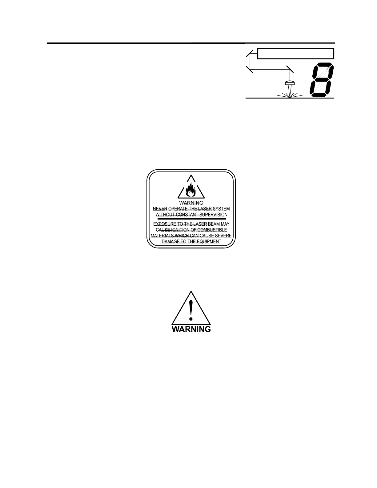
8-1
SECTION 8
Sample Materials
This section provides driver settings and helpful hints to get started engraving and/or cutting
various materials. These settings are to serve as a starting point and are not necessarily
optimized for each particular application.
Safety
NEVER LEAVE THE SYSTEM RUNNING UNATTENDED FOR ANY REASON. Exposure to
the laser beam can cause ignition of combustible materials. All cutting and engraving should be
constantly supervised.
NEVER OPERATE THE LASER SYSTEM WITHOUT A PROPERLY INSTALLED AND
OPERATING EXHAUST SYSTEM. Some materials when cut or engraved can produce fumes
that are hazardous in concentrated amounts. Also make sure that your room is adequately
ventilated as some materials will continue to produce fumes for several minutes to possibly
hours after the cutting or engraving process has been completed. Since many materials can
produce toxic and possibly caustic fumes or residue, it is advisable to obtain the Material Safety
Data Sheet (MSDS) from the materials manufacturer. The MSDS discloses all of the hazards
when handling or processing that material. The law requires all manufacturers to provide this
information to anyone who requests it.
Page 79

8-2 Sample Materials
DO NOT ENGRAVE OR CUT PVC (Polyvinylchloride) BASED MATERIALS. The fumes are
extremely toxic if you inhale them. The fumes are so caustic that it can chemically destroy the
metal parts of the laser system. Damage to the laser system from this type of abuse WILL NOT
be covered under warranty.
There are many variables that can affect the cutting and engraving process such as differences
in the thickness of the material, density of the material, composition of the material, and the
manufacturing processes used to make the material. Please use these settings as a guideline,
in most cases these settings should work out well, but sometimes may have to be adjusted to
produce desirable results.
In compiling these settings, all samples were run with the resolution set at 500 DPI(except were
otherwise noted). When using a lower resolution in order to achieve greater engraving speeds,
remember that the resolution will be reduced which in turn will reduce quality and depth. In
order to compensate for lower resolution settings, lower the speed and/or increase the power to
achieve the same depth. The opposite applies for higher resolution settings.
Below is a list of the various materials that were tested. The following pages will fully describe
the results of these tests and will offer helpful hints when choosing materials, setting
parameters, and using different techniques to provide the best laser cutting and engraving
results.
• ACRYLIC - CAST AND EXTRUDED
• LEATHER
• ACRYLIC - MIRRORED
• MARBLE
• ALUMINUM - ANODIZED
• MAT BOARD
• BRASS - COATED
• MELAMINE
• CORK
• PLASTIC - ENGRAVERS
• CORIAN / AVONITE / FOUNTAINHEAD
• RUBBER STAMPS
• DELRIN (SEAL PRESS)
• VINYL - SIGN
• GLASS / CRYSTAL
• WOOD / WOOD INLAY
Page 80
Sample Materials 8-3
ACRYLIC - CAST AND EXTRUDED
TYPE
POWER
SPEED
PPI
PASS
DEPTH
LIGHT RASTER ENGRAVING
25
100
500
1
.001”
COMMENTS:
Remove original factory masking from the engraving surface. Leave the masking on the nonengraved surface to prevent accidental scratches.
TYPE
POWER
SPEED
PPI
PASS
DEPTH
DEEP RASTER ENGRAVING
100
70
500
1
.010”
COMMENTS:
This sample engraved deeper than the first sample. Engrave through original masking.
Engraving too deep will lose detail.
TYPE
POWER
SPEED
PPI
PASS
DEPTH
VECTOR ENGRAVING
5
4.0
500 1 .2”
COMMENTS:
Engrave with or without masking.
TYPE
POWER
SPEED
PPI
PASS
DEPTH
VECTOR CUTTING
75
.8
500 1 .2”
COMMENTS:
For the best results, remove the original masking on both sides. Re-mask with transfer tape.
Moisten both sides with water from a spray bottle. Elevate the material at least 1/8” off of the
engraving table.
Page 81

8-4 Sample Materials
ADDITIONAL COMMENTS
There are two types of acrylic available, cast and extruded. Cast turns white or frosted and
extruded remains clear when engraved. Use extruded acrylic for paint filled engraving and cast
for regular engraving. Cast engraves better without masking. Lightly engrave the surface to
frost it with a low power setting such as the first setting listed above. If deep engraving is
desired, it is necessary to mask the acrylic with transfer tape to prevent the smoke from
damaging the clear surface of the acrylic. However, another problem with deep acrylic
engraving is that the intense heat creates a white, crusty, deposit that accumulates along the
edges of the area that was just engraved and is impossible to remove without causing damage.
Engraving lightly and without masking seems to be the better all around alternative.
If only cutting acrylic, extruded works better and is less expensive than cast. The cut edges of
extruded acrylic will appear to be more highly polished and clearer than cast acrylic when laser
cut. When cutting acrylic, it might be necessary to remove both sides of the original masking
and re-mask with transfer tape if cutting through the original masking produces flaming. The
original masking is coated with wax and will not absorb water. If cutting through very thick
acrylic, re-mask both sides with transfer tape and dampen the masking on both sides of the
acrylic with water from a spray bottle. Elevate the acrylic off the table at least 1/8 inch, refocus, then proceed to cut. Elevating the acrylic will allow the beam to completely pass through
the material which allows the smoke and heat to escape from underneath. If cutting directly on
the engraving table, the trapped heat might cause the bottom edge of the cut to pit and distort.
Re-masking and dampening with water will act as a heat sink to pull the laser heat away from
the cutting area resulting in less distortion or heat effected zones (HAZ). When dampening, be
sure not to leave puddles of water. Puddles of water will reduce cutting depth significantly. For
the best results when combining engraving and cutting on the same piece, first engrave lightly
and unmasked. Then mask with transfer tape, dampen, elevate, re-focus, and cut as a
second step.
Paint filling the engraved area is possible by first masking the acrylic or leave on the original
masking then engraving through the masking. Before removing the masking, brush or spray on
some acrylic based or water based paint right on to the masking. When the paint is dry,
remove the masking and the paint will remain in the recessed area of the engraving.
Remember to use extruded acrylic when paint filling and cast acrylic when simply engraving.
Acrylic is extremely flammable. Do not leave the laser system unattended when cutting
or engraving.
Page 82
Sample Materials 8-5
ACRYLIC - MIRRORED
TYPE
POWER
SPEED
PPI
PASS
DEPTH
LIGHT RASTER ENGRAVING
30
100
500
1
.003”
COMMENTS: Engrave unmasked and on the backside in reverse text. Engraving on the front
side of mirrored acrylic will visually produce a double image.
TYPE
POWER
SPEED
PPI
PASS
DEPTH
DEEP RASTER ENGRAVING
100
70
500
1
.010”
COMMENTS: Masking is not necessary because the acrylic is protected from smoke damage
by the mirrored backing.
TYPE
POWER
SPEED
PPI
PASS
DEPTH
VECTOR ENGRAVING
5
4.0
500
1
.005”
COMMENTS: Again, masking is not necessary because the acrylic is protected from smoke
damage by the mirrored backing.
TYPE
POWER
SPEED
PPI
PASS
DEPTH
VECTOR CUTTING
75
1.6
500 1 .1”
COMMENTS: Make sure both sides are masked. Dampen and elevate at least 1/8” above the
engraving table. Two passes make a cleaner cut than one. Cut from the front side of the mirror
to prevent heat distortion of the mirrored back surface.
Page 83
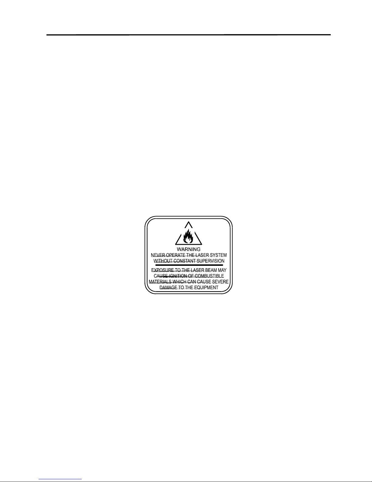
8-6 Sample Materials
ADDITIONAL COMMENTS
Engraving mirrored acrylic is similar to engraving regular acrylic. The idea is to engrave through
the mirrored backing enough to begin to penetrate into the acrylic. Engraving deeply will cause,
a crusty residue to form just like with non-mirrored acrylic. A double image will appear if
engraving on the front side of the mirror. It is not necessary to mask the backside when
engraving because the mirrored backing shields the acrylic from smoke damage. To cut
mirrored acrylic, it might be necessary to remove all original masking, re-mask with transfer
tape, and dampen the tape with water from a spray bottle. Next, place the acrylic in the laser
with the mirrored surface facing upwards and elevate at least 1/8 inch above the table. The
laser beam will not reflect off of the mirrored surface because it is absorbed by the acrylic first.
Sometimes cutting the acrylic from the back side will cause the mirrored backing to distort and
crack from the intense heat required to cut. If the combination of engraving and cutting is
desired, our suggestion is to engrave the backing, unmasked, remove the acrylic, mask both
sides with transfer tape, flip the acrylic over, dampen, elevate, re-focus, and cut from the
front side. When paint filling the engraved area, make sure to use an acrylic based paint or
paint that does not contain acetone or alcohol as these chemicals will crack the acrylic. Water
based paints also work very well. Since the mirrored backing serves as a masking, it is not
necessary to mask the back side before engraving.
Acrylic is extremely flammable. Do not leave the laser system unattended when cutting
or engraving.
Page 84
Sample Materials 8-7
ANODIZED ALUMINUM
TYPE
POWER
SPEED
PPI
PASS
DEPTH
RASTER ENGRAVING
30
100
500
1
.001”
COMMENTS: The power required is dependent on the thickness of the anodized coating. Do
not overpower because the anodized will either be dull in appearance or the engraving lines will
be too thick.
TYPE
POWER
SPEED
PPI
PASS
DEPTH
VECTOR ENGRAVING
10
4.0
500
1
.001”
COMMENTS: Different anodized coatings will require higher or lower power settings. Power
must be increased if engraving at a faster speed.
ADDITIONAL COMMENTS
There is a process called Laser Color Marking which enables the color filling of anodized
aluminum. First, coat or spray the aluminum with a clear acrylic finish. After the finish has
thoroughly dried, laser engrave the graphic onto the aluminum. Then take a water based
marker, such as those found in an art supply store, and swab on the ink into the engraved
area. You can actually see the ink get absorbed into the engraved area but not the unengraved
area. The ink will appear lighter in color because the white engraved area tends to lighten the
shade. Use a darker tint marker to compensate for the lighter effect. Wipe off the excess with a
soft, lint free cloth. Finish the piece by applying another coat of clear acrylic finish and let dry.
Page 85
8-8 Sample Materials
BRASS - COATED
TYPE
POWER
SPEED
PPI
PASS
DEPTH
RASTER ENGRAVING
30
100
1000
1
.002”
COMMENTS: Engrave unmasked. Use a light setting to engrave through the coating. Using
1000 PPI seems to have a cleaner removal of the coating. Some thicker coated brass will
require more power. Too much power loses resolution and washes out finer detail.
TYPE
POWER
SPEED
PPI
PASS
DEPTH
VECTOR ENGRAVING
15
4.0
1000
1
.002”
COMMENTS: Engrave unmasked. Use enough power to expose the brass. Too much power
will cause thicker engraving lines.
ADDITIONAL COMMENTS
The manufacturing processes for coated brass varies from one vendor to another. Some of the
manufacturers do not polish the brass before coating it. Since CO2 lasers at this power level do
not engrave into metals when the coating is removed, the tarnished brass underneath will have
a dull appearance that will need to be polished with a brass polishing compound. This type of
brass is designed for mechanical engravers that actually remove the metal when engraving
which gives the brass a shine without polishing. Brass that is produced for the laser engraving
industry is polished, then clear coated, and finally coated with paint. When laser engraving this
type of material, adjust the power so that the laser beam removes the painted coating but not
the clear coating. This will expose the polished, clear coated brass without penetrating all the
way down to the metal. Since the brass is already clear coated and polished, it will not require
any cleanup after engraving nor will it ever oxidize. If too much laser power is used, the brass
the clear coat will be removed and the brass underneath will be exposed to the heat of the laser
beam causing instant tarnish. The same goes for enamel coated pens, some are polished and
clear coated underneath, and others are tarnished which will require polishing after engraving.
If polishing the brass, use a soft, non-abrasive cloth or tissue and good quality brass polish.
Be careful not to rub too hard as this will scratch the painted coating. Do not use paper towels
either because they will scratch also. Clear coated brass can also be engraved and the
engraved area turned black with an oxidizer giving exceptional results. Test clear coated brass
from different vendors as not all of them will work properly. If the brass, after being engraved,
does not oxidize with the acid solution, apply automotive fine grit rubbing compound to the
engraved area with a soft cloth. This will remove any clear coat that is remaining and will allow
the brass to oxidize with the acid. Apply the same parameters and engraving techniques when
using coated aluminum.
Page 86
Sample Materials 8-9
CORIAN / AVONITE / FOUNTAINHEAD
TYPE
POWER
SPEED
PPI
PASS
DEPTH
RASTER ENGRAVING
100
70
500
1
.005”
COMMENTS: Mask first before engraving if planning to paint fill.
TYPE
POWER
SPEED
PPI
PASS
DEPTH
DEEP RASTER ENGRAVING
100
35
500
1
.015”
COMMENTS: Mask first if planning to paint fill.
TYPE
POWER
SPEED
PPI
PASS
DEPTH
VECTOR ENGRAVING
50
4.0
500
1
.010”
COMMENTS: Mask first if planning to paint fill.
ADDITIONAL COMMENTS
Laser engraving this type of material produces spectacular results especially when the
engraved area is paint filled. If paint filling, it is a good idea to mask first and then engrave
through the masking. In this way, when ready to paint fill, the material is already masked.
Spray painting seems to be the easiest. Using a paint brush is acceptable but time consuming.
Use the paint sparingly. Excess paint can accumulate on the edges of the engraving which will
make mask removal difficult and leave unsightly ridges. It is best to apply several lighter coats
than one heavy coat of paint. Remove the masking after the paint has dried. Engraving this
material without paint filling can work but most of the time there is very little contrast which
makes the engraved area difficult to see.
Page 87
8-10 Sample Materials
CORK
TYPE
POWER
SPEED
PPI
PASS
DEPTH
RASTER ENGRAVING
75
100
500
1
.010”
COMMENTS: Engraved unmasked.
TYPE
POWER
SPEED
PPI
PASS
DEPTH
VECTOR ENGRAVING
10
4.0
500
1
.010”
COMMENTS: Engrave unmasked.
TYPE
POWER
SPEED
PPI
PASS
DEPTH
VECTOR CUTTING
50
1.6
100
1
.060”
COMMENTS: Unmasked. A low PPI setting is used to prevent flaming.
ADDITIONAL COMMENTS
Cork is not very popular for engraving but it does engrave and cut nicely. Cork is mainly used
for making gaskets by vector cutting the gasket patterns.
Page 88
Sample Materials 8-11
DELRIN (SEAL PRESS)
TYPE
POWER
SPEED
PPI
PASS
DEPTH
RASTER ENGRAVING
100
60
500
1
.015”
COMMENTS: Engraved unmasked.
TYPE
POWER
SPEED
PPI
PASS
DEPTH
VECTOR CUTTING
75
2.4
200
1
.060”
COMMENTS: Unmasked. A low PPI setting is used to prevent flaming.
ADDITIONAL COMMENTS
Making a seal using plastic is revolutionizing the industry. The laser can engrave and cut out a
typical Notary Seal in less than 5 minutes. A male and female die must be made as the
diagram below indicates.
Seal Sample
Create the male with a white graphic and a black background. Mirror the image and invert it by
making the background white and the graphic black. Add a .010 inch black outline to the
graphic portion of the female side. This will give the greater clearance to the female side to
prevent the paper from piercing through when the male side of the seal presses into the female
side. Once the seal is made and fastened to the press, make several impressions onto 400 grit
sandpaper to smoothen out the edges of the plastic. Make sure you turn the sandpaper over to
get both sides of the seal.
Page 89
8-12 Sample Materials
GLASS / CRYSTAL
TYPE
POWER
SPEED
PPI
PASS
DEPTH
RASTER ENGRAVING
100
100
500
1
.001”
COMMENTS: Since glass will not vaporize when laser engraving, it does not require a lot of
laser power.
TYPE
POWER
SPEED
PPI
PASS
DEPTH
VECTOR ENGRAVING
8
4.0
500
1
.001”
COMMENTS: Again, since glass will not vaporize, it does not require much laser power.
ADDITIONAL COMMENTS
Glass engraving is different from other types of engraving. A CO2 laser cannot engrave into the
glass nor can it cut glass. Instead, laser interaction with glass causes the surface of the glass
to appear frosted. Sometimes, placing a piece of newspaper on the glass and dampening is
with water will improve the appearance of the engraving. Another method is to apply transfer
tape to the glass, wet it with water from a spray bottle, and laser engrave it. The transfer tape
and water will act as a heat sink and pull the heat away from the glass as the laser system
engraves it. This helps reduce chipping or flaking of the glass.
Be especially careful when engraving leaded crystal. The lead in crystal conduct heat which
can cause much more flaking or even the cracking of the crystal. Use a lower power setting to
try to reduce the chance of damage. It is always good to have at least one extra piece to use as
a test piece to get the right settings especially if you have never tried to engrave that material
before.
If using the optional Rotary Fixture in the Portrait Mode use the following settings to minimize
the chances of the object slipping in the fixture while running at high speeds. If engraving in the
landscape mode, use the settings defined at the top of this page.
TYPE
POWER
SPEED
PPI
PASS
DEPTH
RASTER ENGRAVING
50
50
500
1
.001”
Page 90
Sample Materials 8-13
LEATHER
TYPE
POWER
SPEED
PPI
PASS
DEPTH
LIGHT RASTER ENGRAVING
20
100
500
1
.001”
COMMENTS: Engrave unmasked.
TYPE
POWER
SPEED
PPI
PASS
DEPTH
DEEP RASTER ENGRAVING
60
100
500
1
.010”
COMMENTS: Engrave unmasked. Deeper engraving will require masking to prevent smoke
damage.
TYPE
POWER
SPEED
PPI
PASS
DEPTH
VECTOR ENGRAVING
5
4.0
500
1
.003”
COMMENTS: Engrave unmasked.
TYPE
POWER
SPEED
PPI
PASS
DEPTH
VECTOR CUTTING
50
2.0
200 1 .1”
COMMENTS: Mask top surface and use a low PPI setting when cutting.
ADDITIONAL COMMENTS
Leather is a very simple material to engrave and most types of leather engrave very well with
the laser system. Simulated leather engraves well also, but the results are not as nice as with
the real thing. Engraving lightly will turn the surface of the leather dark brown giving it a high
contrast in appearance. Try engraving at a light power setting first. If the result is not deep
enough the job can be run again over the same spot. Experiment with different depths of
engraving and note the results.
Page 91
8-14 Sample Materials
MARBLE
TYPE
POWER
SPEED
PPI
PASS
DEPTH
RASTER ENGRAVING
100
100
500
1
.003”
COMMENTS: Engrave unmasked. Too much laser power by running too slowly will engrave
too deep and discolor.
TYPE
POWER
SPEED
PPI
PASS
DEPTH
VECTOR ENGRAVING
20
4.0
500
1
.003”
COMMENTS: Engrave unmasked.
ADDITIONAL COMMENTS
Most marble and polished stones will turn white when engraved. Masking is not necessary and
light engraving works out better than heavy and deep engraving. Engraving deeply will cause a
highly detailed image to appear washed out. The objective is to engrave deep enough to turn
the marble white and provide a good contrast. Too much power can also cause the material to
discolor and turn brown as if it were burned. Photographs look great when engraved on marble,
especially darker marbles where the whiteness of the engraving really stands out. Avoid using
marble that is very textured looking. The texture washes out the details of the engraving. Try to
use uniformly colored marble and related stones. Marble can also be paint filled by using a wax
based paint. Rub the paint on with a fingertip, let dry and then buff with a soft cloth. The paint
will only adhere to the engraved surface and not the surrounding areas.
Page 92
Sample Materials 8-15
MAT BOARD
TYPE
POWER
SPEED
PPI
PASS
DEPTH
RASTER ENGRAVING
30
100
250
1
.005”
COMMENTS: Engrave unmasked. A low PPI setting is used to prevent discoloration.
TYPE
POWER
SPEED
PPI
PASS
DEPTH
VECTOR ENGRAVING
20
4.0
250
1
.005”
COMMENTS: Engrave unmasked and at a low PPI setting.
TYPE
POWER
SPEED
PPI
PASS
DEPTH
VECTOR CUTTING
60
4.0
200
1
.050”
COMMENTS: Mask on both sides and elevate above the table at least 1/8”. Use a lower PPI
setting to reduce discoloration of the cutting edge.
ADDITIONAL COMMENTS
Mat board (thick cardboard) is an excellent material to use for architectural modeling and for
picture framing. It cuts and engraves very neatly and cleanly. It comes in a variety of shades
and colors. Patterns can be engraved on the surface with a power setting for light engraving
which just breaks through the very thin top layer and exposes the lighter colored underlying
substrate. When engraving, a low PPI setting is used to prevent overexposure of the
underlying substrate material which causes excessive dark discoloration. Masking is not
necessary on the top surface when engraving. When cutting, both sides might need to be
masked and the material elevated above the engraving table. This will produce an extremely
clean edge on both sides of the material.
Page 93
8-16 Sample Materials
MELAMINE - STANDARD ENGRAVING
TYPE
POWER
SPEED
PPI
PASS
DEPTH
RASTER ENGRAVING
100
70
500
1
.015”
COMMENTS: Engrave unmasked.
TYPE
POWER
SPEED
PPI
PASS
DEPTH
DEEP RASTER ENGRAVING
100
50
500
1
.020”
COMMENTS: Engrave unmasked.
TYPE
POWER
SPEED
PPI
PASS
DEPTH
VECTOR ENGRAVING
20
4.0
500
1
.010”
COMMENTS: Engrave unmasked.
ADDITIONAL COMMENTS
Engraving melamine is very similar to engraving regular wood with the added benefit of a
consistent surface finish and uniform base material composition. Unlike regular wood which has
grain patterns and density variations, melamine when laser engraved produces a flat and even
engraved area. This characteristic gives this material superior engraving and paint filling
qualities. Masking can be used if desired but it is just as easy to spray the engraved area with
water and wipe down with a chamois cloth to remove the smoke residue. Since the top surface
material is consistent in texture and color, engraving photographs or highly detailed images
produces exceptional results. Refer to the next example on engraving photographs and/or
ClipArt.
Page 94
Sample Materials 8-17
MELAMINE - PHOTO/CLIPART ENGRAVING
TYPE
POWER
SPEED
PPI
PASS
DEPTH
RASTER ENGRAVING
75
100
500
1
.008”
COMMENTS: Engrave unmasked. Use a resolution of 500 DPI.
TYPE
POWER
SPEED
PPI
PASS
DEPTH
RASTER ENGRAVING
100
70
500
1
.008”
COMMENTS: Engrave unmasked. Use a resolution of 250 DPI.
ADDITIONAL COMMENTS
Engraving photographs can be challenging at first but becomes easier once there is an
understanding of what to look for and how to achieve the desired results. In an image
processing software, scan the image in at 300 DPI. Adjust the brightness and the contrast to
brighten the light colors and darken the dark colors. The photo might look better by using a
sharpening filter to sharpen up the image slightly. The next step is to select a halftone pattern.
Usually, imaging software gives the choice of using different halftone patterns including
frequency of lines per inch and pattern angles. Use a line frequency above 20 and below 100.
The size of the dots decreases as the line frequency increases. Experiment to see which
pattern looks the best. Big dots look good on some materials and small dots look better on
others. If it is not possible to assign a halftone pattern in the imaging software, the printer
driver will automatically default to a predetermined pattern based on RESOLUTION. Refer to
the chart below.
RESOLUTION
ANGLE
SHAPE
LINES PER INCH
1000
45 DEGREES
ROUND
180
500
45 DEGREES
ROUND
90
333
45 DEGREES
ROUND
60
250
45 DEGREES
ROUND
45
200
45 DEGREES
ROUND
36
When using the Clipart mode switch, which prints all Clipart or drawings as grayscale bitmaps,
use the same parameters and techniques as for engraving photographs.
Page 95
8-18 Sample Materials
PLASTIC - ENGRAVERS MICROSURFACED
TYPE
POWER
SPEED
PPI
PASS
DEPTH
RASTER ENGRAVING
25
100
500
1
.003”
COMMENTS: Remove original masking and leave unmasked. Use enough power to remove
the surface material and expose the underlying substrate.
TYPE
POWER
SPEED
PPI
PASS
DEPTH
DEEP RASTER ENGRAVING
100
90
500
1
.015”
COMMENTS: On thicker plastics, remove the original masking and leave unmasked. Set the
power high enough to assure the full removal of the top surface and to remove some of the
substrate material. Sometimes it may be better to make two passes a lower power setting.
TYPE
POWER
SPEED
PPI
PASS
DEPTH
VECTOR CUTTING
60
1.6
150
1
.060”
COMMENTS: Remove original masking. Mask with transfer tape on both sides. Dampen both
sides with water and elevate off the table. Make 1 to 2 more passes when cutting thicker
plastics.
ADDITIONAL COMMENTS
Engravers plastic comes in many different colors, thickness, coatings, and surface textures.
About 75 % of the available engravers plastic, including ADA signage materials, will engrave
and cut well with the laser system. Microsurfaced plastics seem to work the best because there
is less surface material to remove to uncover the substrate. Since most plastics have low
melting points, a low PPI setting is used when cutting to reduce the possibility of melting.
Masking and dampening with water also helps to reduce melting and keeps the plastic clear of
smoke residue. Always remove the original clear masking from the plastic because it does not
react well with the laser. Since there are so many types of engravers plastics, the only true
way to find out if a particular brand and type will work well with the laser is to experiment. Use
these power settings as a guideline for experimentation and adjust as necessary. Be creative
when engraving this type of material because amazing results will be produced that cannot be
reproduced with a mechanical engraver.
Page 96

Sample Materials 8-19
RUBBER STAMPS
TYPE
POWER
SPEED
PPI
PASS
DEPTH
RASTER ENGRAVING
100
30
500
1
.030”
COMMENTS: Different blends and densities of rubber will engrave to different depths. Test the
rubber first to determine the correct power settings.
TYPE
POWER
SPEED
PPI
PASS
DEPTH
VECTOR CUTTING
40
1.6
150
1
.040”
COMMENTS: Keep the PPI low to prevent flaming while cutting.
TYPE
POWER
SPEED
PPI
PASS
DEPTH
PERFORATED CUTTING
60
1.6
80
1
.020”
ADDITIONAL COMMENTS
Our rubber stamp option is revolutionizing the rubber stamp industry. With special electronics
and a special system driver, it is possible to engrave rubber stamps with a profile and cut out
the stamp in one easy step. The machine produces a taper on each character so that the base
of the character is wider than the top printing surface giving greater stability when stamping. If
trying to engrave stamps without this option, the letters will not have a profile, be very thin and
flimsy, and will collapse while stamping them. If you do not have this option and would like to
add it to your system, please contact one of our engineers in the sales department for current
pricing. All laser systems can be upgraded to have this extraordinary feature.
In the above example, only one pass is necessary to achieve a deeply engraved rubber stamp.
When cutting out the rubber stamp, we recommend using a very low PPI setting. This setting
spreads the laser pulses far enough apart that they just touch at the edges. The result is a
perforated cut that allows the rubber stamp to remain attached to the entire sheet but easily
removed by simply tearing it off. The advantage to this is that the possibility of distortion or
melting while cutting is virtually eliminated and the entire sheet of rubber stamps can be
removed from the machine at one time instead of having to pick them up one by one. Some
blends of rubber produce a powdery residue when engraved. Using compressed air and
blowing off the residue usually will clean the rubber effectively, but please clean the rubber
outside of the laser system.
Page 97
8-20 Sample Materials
SIGN VINYL
TYPE
POWER
SPEED
PPI
PASS
DEPTH
RASTER ENGRAVING
100
50
500
1
.015”
COMMENTS: These parameters are for engraving vinyl on wood. Apply the vinyl to the wood
and squeegee out air bubbles. Mask with transfer tape. Engrave deep enough to go through
the tape, vinyl, and into the wood. Make a second pass to go deeper. Engraving at a slower
speed might cause the vinyl to melt.
TYPE
POWER
SPEED
PPI
PASS
DEPTH
VECTOR CUTTING
5
4.0
500
1
.003”
COMMENTS: Unmasked, cuts through vinyl and not the backing. Thicker vinyl requires more
power and thinner ones require less. Adjust as necessary.
ADDITIONAL COMMENTS
Sign vinyl comes in a wide variety of colors, patterns, thickness, finishes, and reflectivity.
There are a few methods for using sign vinyl with the laser system. One method is to vector cut
(unmasked) through the vinyl but not through the backing. This technique provides results
equivalent to a vinyl cutter machine. Once the vinyl has been cut, remove the excess vinyl,
apply transfer tape and use a squeegee to remove trapped air bubbles. The transfer tape can
then be lifted off and the vinyl lettering or objects that were vector cut will stick to the transfer
tape and maintain their correct spacing with respect to each other. Now apply the tape to the
desired surface and squeegee, peel off the transfer tape, and the lettering will remain adhered
to the surface. The other method is to apply a piece of vinyl to the desired surface (unmasked)
and adjust the laser power so as to cut through the vinyl without engraving into the material
below. Another popular example of the use of vinyl is to cover the entire surface of a wooden
plaque with vinyl, use a squeegee to remove all air bubbles, and then mask the entire surface
with transfer tape to protect the vinyl from smoke damage due to the wood engraving involved.
In the graphics software, color the background one of the eight driver colors and place white
filled text on top of the colored background. Since the laser system does not engrave white
filled objects, the background will be engraved and the lettering will be untouched. Then peel
off the excess vinyl and transfer tape to reveal the final product. The lettering will be raised and
vinyl coated.
Page 98
Sample Materials 8-21
WOOD
TYPE
POWER
SPEED
PPI
PASS
DEPTH
RASTER ENGRAVING
100
70
500
1
.020”
COMMENTS: Engrave unmasked. If masking, reduce the speed setting to 50% to get the
same depth.
TYPE
POWER
SPEED
PPI
PASS
DEPTH
VECTOR ENGRAVING
40
10
500
1
.030”
COMMENTS: Engrave unmasked.
TYPE
POWER
SPEED
PPI
PASS
DEPTH
VECTOR CUTTING
50
1.6
250
1
.125”
COMMENTS: Elevate at least 1/8” off of the engraving table. Lightly dampen bottom side with
water. Both surfaces can also be masked and dampened with water. Elevating will let heat and
smoke escape from underneath and prevent burning.
ADDITIONAL COMMENTS
When engraving wood with a laser, a brown, maple syrup like residue will deposit on the
surface of the wood. This is normal and impossible to eliminate by POWER, SPEED, or PPI
changes. More residue will be present when engraving deeper and/or slower. This residue
washes off with water and a sponge. We recommend using a kitchen sponge with a nylon
string mesh wrapped around it. Dampen the sponge and wipe off the residue. A damp chamois
cloth works well also. Do not use paper towels or a regular sponge because these materials will
get lodged in the engraved area when wiping and are extremely difficult to remove. A method to
avoid cleanup is to mask the wood with transfer tape and peel off the tape after engraving. If
desired, after engraving and before peeling off the tape, spray paint can be applied to color fill
the engraved areas. After the paint dries, peel of the tape. If an intricate drawing has been
engraved and there are many small pieces of tape to remove, it may be easier to flood the
masking, after engraving, with water. This will loosen the tape and it can be easily removed by
rubbing it off by hand. In the vector cutting example, the wood was elevated from the table to
let smoke and heat escape from underneath. If elevating the wood, mask and/or dampen the
bottom side of the wood very lightly and the water acts as a heat sink to prevent the underside
from flaming and charring. Elevating the wood also helps to determine whether the laser has
passed completely through since the cut
Page 99

8-22 Sample Materials
pieces will fall through to the table when cutting is finished. If raising the wood, set up the
drawing so that the inner pieces of the drawing are cut first, otherwise pieces may fall through
at the wrong time.
Not all wood finishes are created equal. When ordering wood from a supplier, be sure to
specify that it is being used for laser engraving. Some finishes cannot handle the heat from the
laser and will bubble, blister, and possibly turn white. For engraving softer woods such as pine
or balsa, reduce the power settings to acquire the best depth. Engraving too deep on soft
woods will reduce quality. Every type of wood will engrave differently. Experiment with different
types of wood and note the results. It is better to engrave woods that are finished. If engraving
unfinished wood and it is not masked with transfer tape, the smoke residue tends to embed in
the wood and is impossible to remove without sanding. To prevent this, mask all unfinished
wood with transfer tape.
WOOD INLAYS - VENEERS
Create a drawing with no outlines, only filled areas. Engrave the filled areas almost as deep as
the thickness of the veneer (usually about .003 inches (.1 mm) or less). With some water and a
nylon brush, remove all residue from the engraved area. When cutting veneers make sure they
are lying absolutely flat. In the drawing, give the objects an outline of .001 inches (.1 mm) and
remove the fill. Adjust the power so that there is just enough power to cut completely through
the veneer. Overpowering the cut will cause too much material removal and the fit will not be
snug. Some software programs allow outline offsetting to compensate for the thickness of the
beam. This is called contouring and is optimal if planning to do this type of work. Usually, a
contour to the outside of the vector line of .006 inches provides a tight fit. Remember, if using
more power to cut through the veneer, compensate for the thicker width of the laser cut by
contouring a little further to the outside.
Another method, which we believe is a better way, is to first create your graphic and fill it with
the color black. Then give it a white outline of .012 inches (.3 mm). If you look at the graphic
when you add the outline, you will see that it appears to shrink. Now raster engrave the
graphic to a depth slightly shallower than the thickness of the veneer. When the engraving is
finished, place the veneer into the laser system. Take the graphic on screen, remove the black
fill and change the outline to the color red. Also make sure that the red outline thickness is set
to .001 inches (.1 mm) so that it will vector cut. Cut out the veneer with the laser system, add
glue to the veneer, apply the veneer into the engraved area of the other piece of wood, and let
dry. After the glue has thoroughly dried, sand the veneer until it is flush with the base wood. A
good veneer to use are those with an adhesive backing. Once cut, place the veneer into its
proper place on the engraved wood block and with a clothes iron, iron the veneer into the
engraved wood. This melts the glue and causes the veneer to stick to the engraved area.
Finish the wood as you desire and the finished product will look fantastic.
The veneer can now be sanded flush with the surface and a finish coat applied.
Page 100
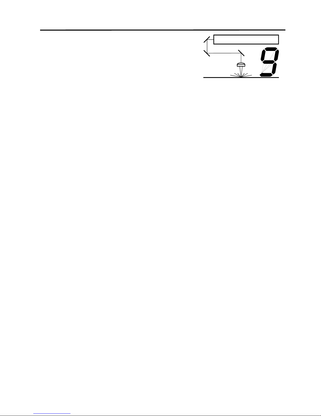
9-1
SECTION 9
Maintenance
Keeping the laser system clean will ensure the highest quality engraving. The frequency of
cleaning will depend entirely on the type of material being engraved, the performance of your
exhaust blower, the operating environment, and the amount of laser system usage over a given
period of time. Dirt or debris that is allowed to build up on the motion system components will
cause uneven or rough engraving, or loss of engraving position as well as premature
component failure. Smoke or dirt buildup on the optics can cause damage to them, loss of laser
power, or premature failure of these components. Use good judgment and keep in mind that a
clean machine is the best performing machine.
Always turn the laser engraving system OFF and unplug it before performing any cleaning
procedures.
Suggested Cleaning and Maintenance Supplies
• Soap solution mixture of 1 tablespoon (2 cl) liquid soap and 1 quart (liter) of water in a spray
bottle
• Paper towels
• Cotton cloth
• Denatured alcohol (NOT to be used on any painted surface, plastic, or the Top Window)
• Acetone (can be used on the engraving table but nowhere else)
• Cotton swabs (supplied)
• Lens cleaner (supplied)
• Lens tissue (supplied)
• Vacuum cleaner
• Set of Allen wrenches sized from .050 to 3/16 inch
*NOTE: When using acetone or denatured alcohol, please follow the instructions on the printed
label of these materials for safe handling procedures.
Please familiarize yourself with the motion system components in the following diagram. It will
help you understand which components need periodic cleaning.
 Loading...