

Hermann Supermaster 28 E, Supermaster 23 e, Supermaster 30 SE, Supermaster 24 SE Instruction Manual
Page 1

INSTRUCTIONS MANUAL
FOR THE GAS BOILER
Supermaster
23 E – 28 E
24 SE – 30 SE
ATTENTION
(for SUPERMASTER 24/30 SE)
FOR DIAPHRAGM POSITIONING, CAREFULLY READ THE FLUE SYSTEMS
INSTRUCTIONS IN THE “INSTALLATION” CHAPTER.
IMPORTANT
THE FIRST IGNITION OF THE BOILER MUST BE EXECUTED BY AN
AUTHORIZED TECHNICIAN ACCORDING TO THE LAW 46/90.
Assigning all the operations for the first ignition to a Hermann Authorized Service
Center the particular and exclusive Hermann Conventional Warranty is activated.
For further information consult the coupon which you can find in the boiler’s
documents envelope.
Assigning all the operations for the first ignition to a Hermann Authorized Service Center the particular and exclusive Hermann
Conventional Warranty is activated. For further information consult the coupon which you can find in the boiler’s documents envelope.
Page 2
2
sections for the usersections for the technician
Index
DANGER: All warnings preceded by this symbol MUST be carefully respected so as
to avoid any accident of mechanical (e.g. wounds or contusions) or general origin.
DANGER: All warnings preceded by this symbol MUST be carefully respected so as
to avoid any accident of ELECTRICAL origin (fulguration).
DANGER: All warnings preceded by this symbol MUST be carefully respected so as
to avoid any accident of THERMIC origin (scalds).
Attention: All warnings preceded by this symbol MUST be carefully respected so as to avoid
any disfunctioning and/or damage to the appliance or other objects.
Introduction ..................................3
Technical data...............................4
Installation ....................................8
Safety laws and rules referred to technicians
assigned to boilers installation .............. 8
Laws and rules referred
to boilers installation .............................. 8
Boiler location.............................................. 9
Boiler hanging ........................................... 10
Hydraulic connections ............................... 11
System filling ............................................. 12
Gas connection ......................................... 13
Electrical connections ............................... 14
Chimney connections
SUPERMASTER E (natural draught) .. 15
Chimney connections
SUPERMASTER SE (forced draught) . 16
High capacity fan
SUPERMASTER 24 SE....................... 18
Flue systems
SUPERMASTER SE............................ 19
Instructions for first ignition,
regulation and maintenance......21
Access to the regulation devices .............. 21
Opening of the sealed chamber ................ 21
Prefilling of the DHW expansion vessel .... 22
Preliminary GAS checkings....................... 22
Gas valve pressure regulation (MAX-MIN) 23
Slow opening regulation ............................ 24
Regulation of MAX heating power............. 24
Changing Gas type ................................... 27
Combustion check ..................................... 28
Draining heating system
and tank serpentine ............................. 28
Draining the tank ....................................... 29
Check and replacement
of the magnesium anode ..................... 29
Hydraulic section ....................................... 30
Electronical regulation ............................... 32
Warnings for servicing............................... 33
Components of the gas boiler
SUPERMASTER 23 E - 28 E .............. 34
Components of the gas boiler
SUPERMASTER 24 SE - 30 SE ......... 35
Electric diagram for
SUPERMASTER 23 E - 28 E .............. 36
Electric diagram for
SUPERMASTER 24 SE - 30 SE ......... 37
User instructions ........................ 38
Warnings for first starting up ..................... 38
Useful advices ........................................... 38
Warnings ................................................... 39
Boiler controls ........................................... 40
Instructions for boiler ignition,
functioning and turning off ................... 40
Working and warning indicators ................ 42
Boiler inactivity .......................................... 44
Incidental not functioning .......................... 46
User warnings ........................................... 47
MANUFACTURER DECLARATION
Hermann boilers have obtained the CE certification (DM dtd. April 2nd 1998, Law 10/91, art. 32) and
meet minimum efficiency requirements, both at normal and 30% load, provided by DPR 412/93
(according to Law 10/91, art. 4, sub-section 4). They are in conformity with following Directives: Directive
on appliances burning gaseous fuels (90/396), Directive on electro-magnetic compatibility (CE 89/
336), Efficiency Directive (CE 92/42), Low Voltage Directive (CE 73/23), and relevant modifications.
Page 3

3
Introduction
for the technician and for the user
INTRODUCTION
The instructions manual is an essential and complementary part of the product and it is
supplied together with the boiler.
Carefully read the manual, achieving all important information for a safe installation,
use and servicing.
— Carefully keep the manual for any further consultation you may need.
— The installation must be carried out by a qualified technician, in accordance with
manufacturer instructions and with the relevant requirements of the current issue.
— A qualified technician is a person with a specific technical competence in the field of the
heating appliances for domestic use and domestic hot water production, as indicated
by the Law [ID of Your National rule, if any, regarding Technicians competence].
— User can ONLY make those operations that are specifically described in the “USER
INSTRUCTIONS” section.
— The manufacturer has no contractual and extra-contractual responsibility for any damage
arising from wrong installation, wrong use and non-observance of current laws and
instructions given by the manufacturer himself.
— Important: this gas boiler is used to heat the water at a temperature lower than the boiling one,
at atmospheric pressure; it must be connected to an heating system and/or to a domestic hot
water system, in accordance with its features and power.
— Packing items (cartons, nails, plastic bags and so on) must not be left within children
easy reach, as they are potentially dangerous.
— Before any cleaning or servicing operation, switch off the main electrical switch of the
heating system and/or any other suitable switch providing electrical disconnection of
the gas boiler.
— In case of fault and/or bad operation of the appliance, disconnect it immediately and do
not try to repair it by yourselves.
Boiler servicing and repair must be carried out exclusively by [HERMANN Authorized Servicing
Centres] [qualified technicians], which will use original spare parts. Strictly observe the above
requirement, avoiding any risk of compromising the appliance safety.
— If the appliance should be definitively disconnected, remove or cut off any potential dangerous
item.
— When selling the appliance or leaving it installed after a removal, make always sure that the
instructions manual is close to the boiler for the future use of new owners and/or installers.
— This appliance must be used for its clearly recommended utilization only. Any other utilization
must be considered dangerous and incorrect.
— It is strictly forbidden to use the appliance for different purposes than the specified ones.
— This appliance must be installed exclusively to wall.
Page 4
4
Technical data
for the technician
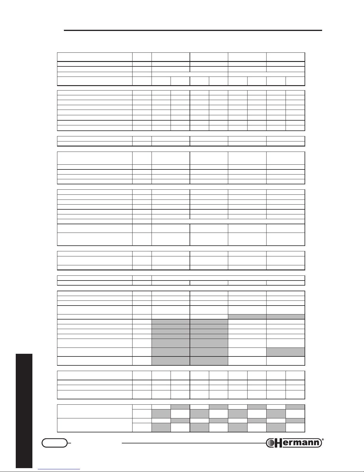
TECHNICAL DATA
ATADLACINHCET.M.U
RETSAMREPUS
E32
RETSAMREPUS
E82
RETSAMREPUS
ES42
RETSAMREPUS
ES03
noitacifitrecEC
°n0173NB49600173NB49600173NB49600173NB4960
ssalC
II
+3H2
II
+3H2
II
+3H2
II
+3H2
epyT
SB/11B 28C-26C-25C-24C-23C-21C-22B
epytsaG
02G
/03G
13G
02G
/03G
13G
02G
/03G
13G
02G
/03G
13G
)iH(tupnitaehxaM
Wk6.526.525.030.036.526.527.232.23
)iH(tupnitaehniM
Wk5.015.012.312.315.015.012.312.31
)iH(tuptuotaehxaM
Wk1.321.325.721.726.326.325.921.92
)iH(tuptuotaehniM
Wk1.91.94.114.119.89.80.110.11
ON
x
ssalC
21213131
ONdethgieW
x
hWk/gm261752271802231242631242
tupnilanimontaOC
mpp9307043512043304
OC
2
tupnilanimonta
%7.46.51.52.65.66.71.66.7
YCNEICIFFE
ycneiciffelanimoN
%8.094.191.294.39
daol%03taycneiciffE
%1.888.984.783.09
GNITAEH
retawfoegnarrutarepmeT
xam÷nimtiucricgnitaehni
)egnardecuder(egnardradnats
C°
08÷03
)54÷52(
08÷03
)54÷52(
08÷03
)54÷52(
08÷03
)54÷52(
)gnitaeh(lessevnoisnapxE
l01010101
erusserplessevnoisnapxE
rab1111
erusserpgnikrowxaM
rab3333
erutarepmetmetsysxaM
C°58585858
RETAWTOH
esirerutarepmetC°52taetarwolF
nim/l2.318.515.319.61
esirerutarepmetC°03taetarwolF
nim/l0.112.313.111.41
)526NErp(etarwolfcificepSnim/l314.51315.61
yticapacknaTl06060606
erusserpylppusxaM
rab6666
)WHD(lessevnoisnapxE
l2222
erusserplessevnoisnapxE
rab )retawtelniehtsaerusserpemasehttaegrahc(
yb)xam÷nim(teltuoWHDfoegnarerutarepmeT
)egnartrofmocrepuS(evlavgniximlaunam
C°84÷5384÷5384÷5384÷53
fo)xam÷nim(egnarnoitalugerdewollacinortcelE
noevlavgniximlaunam(reliobehtniWHD
)noitisopreliobrepuS
C°56÷5556÷5556÷5556÷55
ATADLACIRTCELE
ycneuqerf/egatloV
zH/tlov05/03205/03205/03205/032
noitpmusnocrewoP
)nafyticapachgihhtiw=PAV(
W001031)PAV061(051081
noitcetorpfoleveL
D4XPID4XPID4XPID4XPI
SNOISNEMID
htdiW htpeD-thgieH-
mm
margaid"SNOISNEMID"otrefeR
)knatytpmehtiw(thgieWgk67970838
)teltuO=S(SNOITCENNOC
nruter/wolfgnitaeH
hcnI"¾"¾"¾"¾
teltuo/telniretaWcitsemoD
hcnI"½"½"½"½
reliobehtotnoitcennocsaG
hcnI"¾"¾"¾"¾
kcocsagehtotnoitcennocsaG
tiknoitcennocdradnatsfo
hcnI"½"½"½"½
ØteltuostcudorpeulF
mm031041
Øtelniria/teltuostcudorpeulflaixaoC
mm
06/00106/001
xam/nim)latnoziroh(htgneleulflaixaoC
m
4÷5.03÷1
xam/nim)lacitrev(htgneleulflaixaoC
m
5÷14÷1
Øtelniria/teltuostcudorpeulfetarapeS
mm
0808
xam/nimhtgneleulfetarapeS
m
03÷2
)02=Sxam(
61÷2
)01=Sxam(
xam/nimhtgneleulfetarapeS
htiw nafyticapachgih
m
06÷13
)04=Sxam(
htgneleulfetarapeS
xam/nimtilps-sepiphtiw
m
41÷2
)31=Sxam(
01÷2
)7=Sxam(
ERUSSERPYLPPUSSAG
epytsaG02G
/03G
13G
02G
/03G
13G
02G
/03G
13G
02G
/03G
13G
erusserplanimoN
rabm0273/920273/920273/920273/92
rebmunsrotcejnI
3131414131314141
retemaidsrotcejnI
Ø
mm001/1
02157/5752167/6702157/5703187/87
NOITPMUSNOCSAG
xamQ
h/cm17.2
22.3 17.2 64.3
h/gk
/10.2
89.1
/63.2
33.2
/10.2
89.1
/35.2
05.2
nimQ
h/cm11.1
04.1 11.1 04.1
h/gk
/38.0
18.0
/40.1
20.1
/38.0
18.0
/40.1
20.1
Page 5
5
Technical data
for the technician
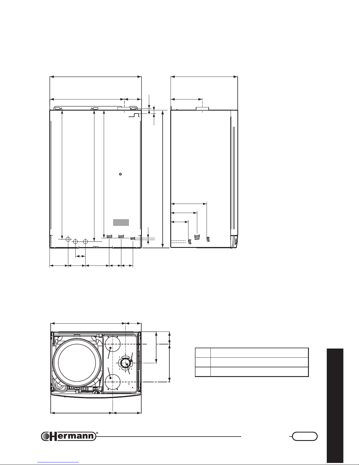
DIMENSIONS
1teltuostcudorpeulF
2metsyslaixaocroftelniriA
3metsysetarapesroftelniriA
SuperSuper
SuperSuper
Super
master 24-30 SEmaster 24-30 SE
master 24-30 SEmaster 24-30 SE
master 24-30 SE
models only:
SuperSuper
SuperSuper
Super
master E - SEmaster E - SE
master E - SEmaster E - SE
master E - SE
411 189
207
250 82
496
3
2
1
7
6
2
R
0
0
104
600
900
438
462
496
(mod. E)
(mod. SE)
138
104
761R02
207
848
871
860
11
18
95 124
52
163 6989
132
145
208
G
TA / L
RI F
CMR
F
(RI*)
C
R
M
G
4
C Hot water outlet (1/2”)
RI Re-circulation Return (1/2”)
(only if optional kit is installed)
F Cold water inlet (1/2”)
R Heating return (3/4”)
M Heating flow (3/4”)
TA/L Zone for electrical power
supply and room thermostat
connections
G Gas (3/4”)
(RI*) Optional Re-circulation Kit
ends with a simple pipe facing
the wall.
Page 6
6
Technical data
for the technician
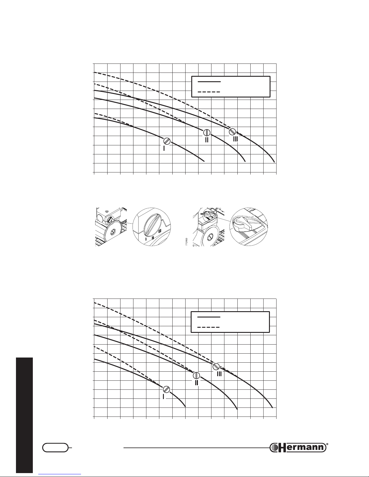
AVAILABLE PUMP CAPACITY
Model
SUPERMASTER 23 E / 24 SESUPERMASTER 23 E / 24 SE
SUPERMASTER 23 E / 24 SESUPERMASTER 23 E / 24 SE
SUPERMASTER 23 E / 24 SE
with selector in speed position I, II, III
AVAILABLE PUMP CAPACITY
Model
SUPERMASTER 28 E / 30 SESUPERMASTER 28 E / 30 SE
SUPERMASTER 28 E / 30 SESUPERMASTER 28 E / 30 SE
SUPERMASTER 28 E / 30 SE
with selector in speed position I, II, III
0
0,5
1
1,5
2
2,5
3
3,5
4
4,5
5
5,5
6
0 200 400 1000 1200600 800 1400
Portata l/h
Prevalenza m H
2
O
711_1
R00
By-pass automatico
By-pass escluso
Water flow l/h
Pressure m. H
2
O
Automatic by-pass
Excluded by-pass
0
0,5
1
1,5
2
2,5
3
3,5
4
4,5
5
5,5
6,5
6
0 200 400 1000 1200600 800 1400
712_1
R00
Portata l/h
Prevalenza m H
2
O
By-pass automatico
By-pass escluso
Water flow l/h
Pressure m. H
2
O
Automatic by-pass
Excluded by-pass
Page 7
7
Technical data
for the technician
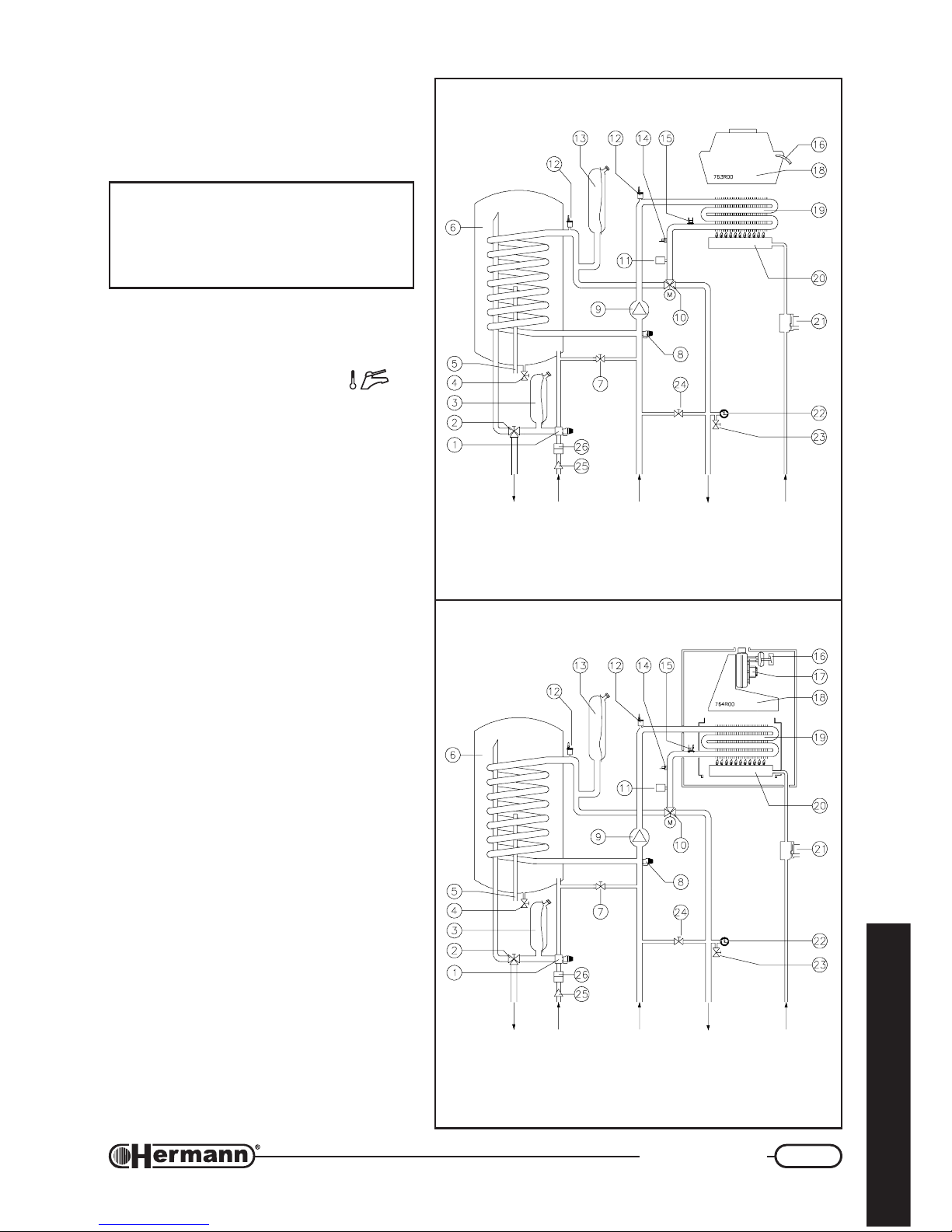
BOILER SCHEMATIC
SUPERMASTER ESUPERMASTER E
SUPERMASTER ESUPERMASTER E
SUPERMASTER E
SUPERMASTER SESUPERMASTER SE
SUPERMASTER SESUPERMASTER SE
SUPERMASTER SE
1 DHW circuit safety valve (8 bar)
2 Manual DHW mixing valve (Knob
)
3 DHW expansion vessel
4 Tank drain tap
5 Tank Temperature sensor
6 Tank
7 Heating circuit filling tap
8 Heating circuit safety valve (3 bar)
9 Circulator
10 Motorized 3 way valve
11 Water pressure switch
12 Air outlet valve
13 Heating circuit expansion vessel
14 Heating temperature sensor
15 Safety thermostat
16 Flue thermostat (“E” models)
Flue pressure switch (“SE” models)
17 Fan (“SE” models)
18 Chimney (“E” models)
Flue Conveyor (“SE” models)
19 Primary exchanger
20 Burner
21 Gas valve
22 Thermometer + Heating circuit Gauge
23 Heating circuit drain tap
24 System By-pass
25 Filter
26 Litercounter
DOMESTIC
WATER
GAS
INLET
HEATING
FLOW
OUTLET
RETURN
DOMESTIC
WATER
GAS
INLET
HEATING
FLOW
OUTLET
RETURN
WARNING: This scheme is made for information only. To make boiler hydraulic connection either use fixing jig or the
drawing inserted in the section “Installation” or the “Dimensions” drawing.
Page 8
8
Installation
for the technician
INSTALLATION
Safety laws and rules referred to technicians
assigned to boilers installation
Place here all necessary
advices according to national rules
about WORK SAFETY
Law number XXXX
“Actuation of 89/391/CEE; 89/655/CEE, 90/296/CEE, 90/934/CEE, 90/679/CEE, (work safety)”
Law number XXXX
“Actuation of 89/686/CEE (21 Dec 1989)”
Other Law number XXXX (if any)
“Other Law title and/or brief description”
Directives
“Directive title and/or brief description”
Always proceed with caution when handling the boiler and carrying out
installation/maintenance work as metal parts may cause injuries such as cuts
and abrasions. Wear gloves while doing the above mentioned operations.
Laws and rules referred
to boilers installation
Place here all necessary
advices according to national rules
about BOILER INSTALLATION
Law number XXXX
“Law title and/or brief description”
Page 9
9
Installation
for the technician
Boiler location
INSTALLATION ROOM
When having an heat ouput lower than 35 kw (about 30000 Kcal/h), particular features for the
installation room are not required. Shortly, all installation rules assuring a safe and regular gas
boiler operation, must be strictly respected.
Place here all necessary
advices according to national rules about:
- Installation room requirements
- Limitations in power and/or number of boilers and other
appliances in the same room
Law number XXXX
“Law title and/or brief description”
ROOM VENTILATION (mod. SUPERMASTER 23/28 E – natural draught)
When a natural draught boiler is installed, permanent ventilation of the installation
room is mandatory and extremely important. Ventilation must be made and sized in
accordance with Laws and Rules in force.
INSTALLATION IN ROOMS WHERE TEMPERATURE CAN DROP DOWN TO 0°C:
When the installation place does not guarantee an adequate repair against atmospheric agents,
the gas boiler must be completely protected through an adequate coverage as a safety measure
against the above agents.
Thanks to its antifreeze system, inner components could never reach a temperature lower than
5°C. This system is activated when the boiler is connected to the electrical and gas supply lines.
In case of boiler installation in rooms where temperature can drop down to 0°, it is advisable to
protect the heating circuit with an antifreeze liquid. See the “System Filling” section.
This appliance is not suitable for outdoor installation.
Page 10
10
Installation
for the technician
Boiler hanging
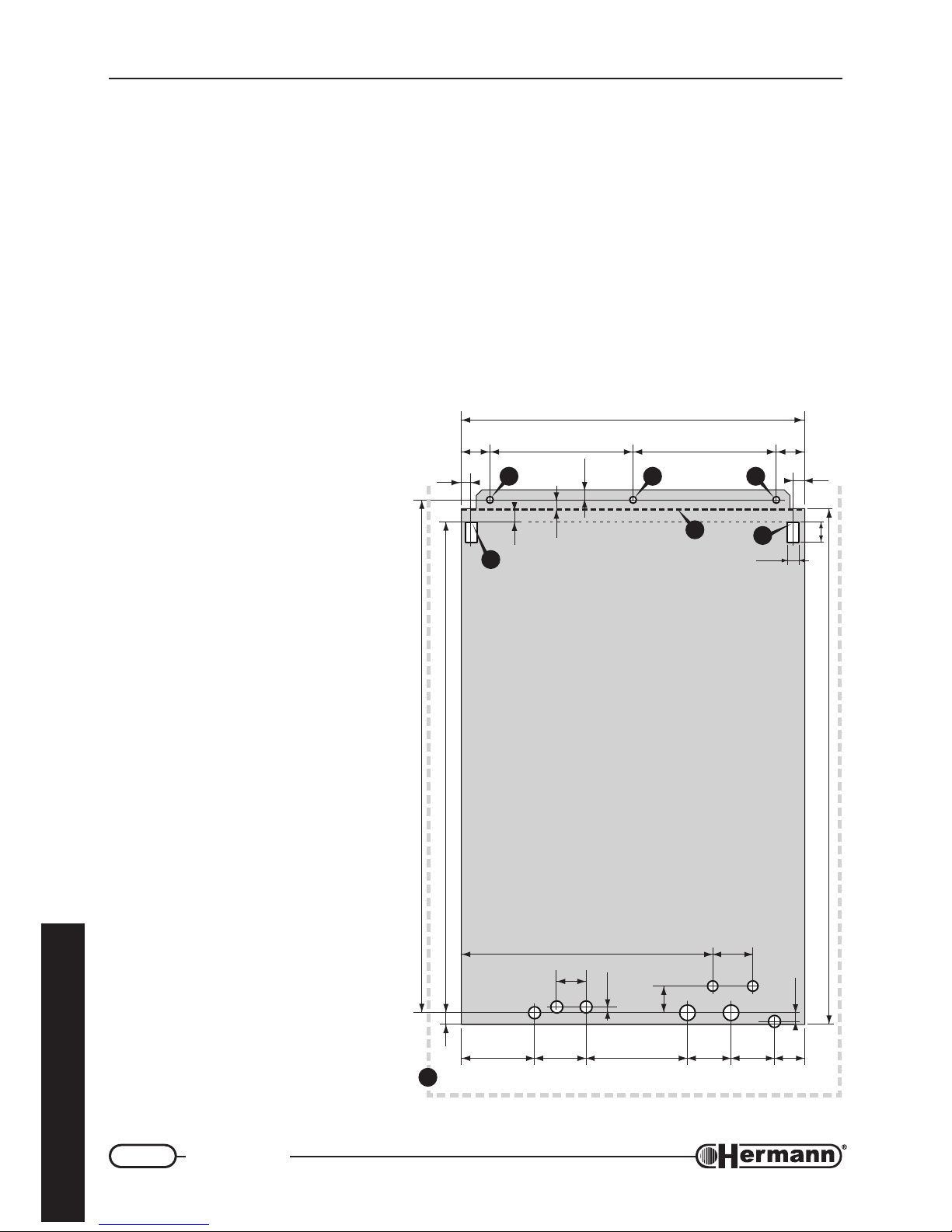
REMARK: A re-utilizable metal jig can be ordered separately, so as to facilitate connections and
fixing points positioning (when the standard connection kit is used). If the standard connection
kit is not used, refer to the “Dimensions” drawing (Technical Data section) for the position of the
connections directly on the boiler.
— Consider gas boiler size and sufficient clearances [E] for servicing/repair. It is recommended:
50 mm left, 150 mm right and 300 mm on lower side;
— To fix the boiler with wallplugs (“stud” type with nut), center the relevant wall holes as regards to
[A] points. To hang it with open hooks, place hooks in correspondence with [B] points.
— Using the jig or respecting the measures indicated in the figure, fix up electrical connections
and all ducts for heating flow and return, cold water, hot water and gas.
— Hang the boiler to the wallplugs
or hooks, using the holes ([A] for
the wallplugs and [B] for the open
hooks).
— Remove the plastic caps from
the boiler connections prior to
connecting boiler to the pipework.
REMARK: To facilitate boiler
connection, it is possible to
remove temporarily the lower
grid, unscrewing its four screws.
— As far as air inlet and flue outlet
ducts are concerned (forced
draught models), please refer to
“Flue systems” paragraph, where
measures are referred to the
upper edge of boiler’s body [D].
A
B
D
E
A A
B
250 250 50
20
35
50
600
18
18
439
128
RC
FRI
M
G
TAL
90
52
177 76 69 60
70
18
891
900
766R01
86220
10
47
13
11
14
C Hot water outlet (1/2")
RI Re-circulation Return
(optional - 1/2")
F Cold water inlet (1/2")
R System Return (3/4")
M System Flow (3/4")
G Gas (1/2")
L Electric Line
TA Room thermostat
Page 11
11
Installation
for the technician
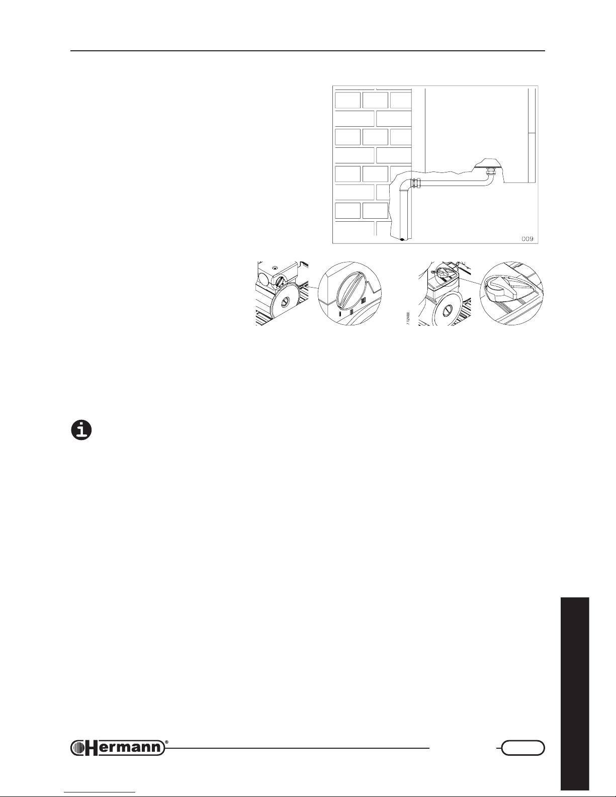
CONNECTION EXEMPLE
Hydraulic connections
ADVICES AND SUGGESTIONS TO AVOID
VIBRATIONS AND NOISES IN THE SYSTEM
— Do not use pipes with reduced diameters;
— Do not use bends with small radius and
reductions of important sections;
— It is recommended an hot washing of the
system in order to purge the pipes and the
radiators from impurities (in particular oils and
fats) that could damage the pump.
PUMP’S SPEED
The pump has a selector which
allows to reduce the speed, so as
to reduce the noise produced by the
too rapid circulation of the liquids in
too small heating systems.
DOMESTIC HOT WATER SUPPLY
The pressure of entrance cold water inlet pressure must be lower than 6 bar. Furthermore, for an
optimal boiler functioning, water pressure should be more than 1 bar. A too low inlet pressure could
impede the correct restore of the heating system pressure, whereas a too high inlet pressure will
cause the opening of the tank safety valve and, for this reason, the water outlet.
In case of stronger pressure it is necessary to install a PRESSURE REDUCER upstream
the boiler.
The cleaning frequency of the coil exchanger depends on the water supply hardness. Besides, the
presence of solid residuals or impurities in the water (for example in case of new systems) could
compromise the correct functioning of the boiler.
However, it is possible to install suitable water treatment device, depending on the water features.
Page 12
12
Installation
for the technician
HEATING SYSTEM
— Verify that the hydraulic pressure measured after the reduction valve is not greater than the
maximum hydraulic pressure indicated on the appliance data plate.
— Considering that during boiler operation, the water inside the heating system increases its
pressure, make sure that its maximum value does not exceed the maximum hydraulic pressure
indicated on the technical data.
— Connect the boiler’s safety valves outlets to an evacuation funnel. If safety valves are not
connected to an evacuation device, their intervention could flood the room. Hermann cannot be
held responsible for any damage arising from that situation.
Make sure that the hydraulic and heating systems ducts are not used as earth
connections of the electrical system. They are absolutely NOT SUITABLE for such a
use.
System filling
In case of installation of the boiler in areas where the room temperature can decrease under
0° C, we suggest to fill the heating system with an anti freezing liquid and to execute the filling
of the tank in a second time, in the process of first ignition of the boiler.
Once all system connections have been carried out, proceed with filling of the water heater tank
and of the heating system. This operation should be made with caution, respecting the following
steps:
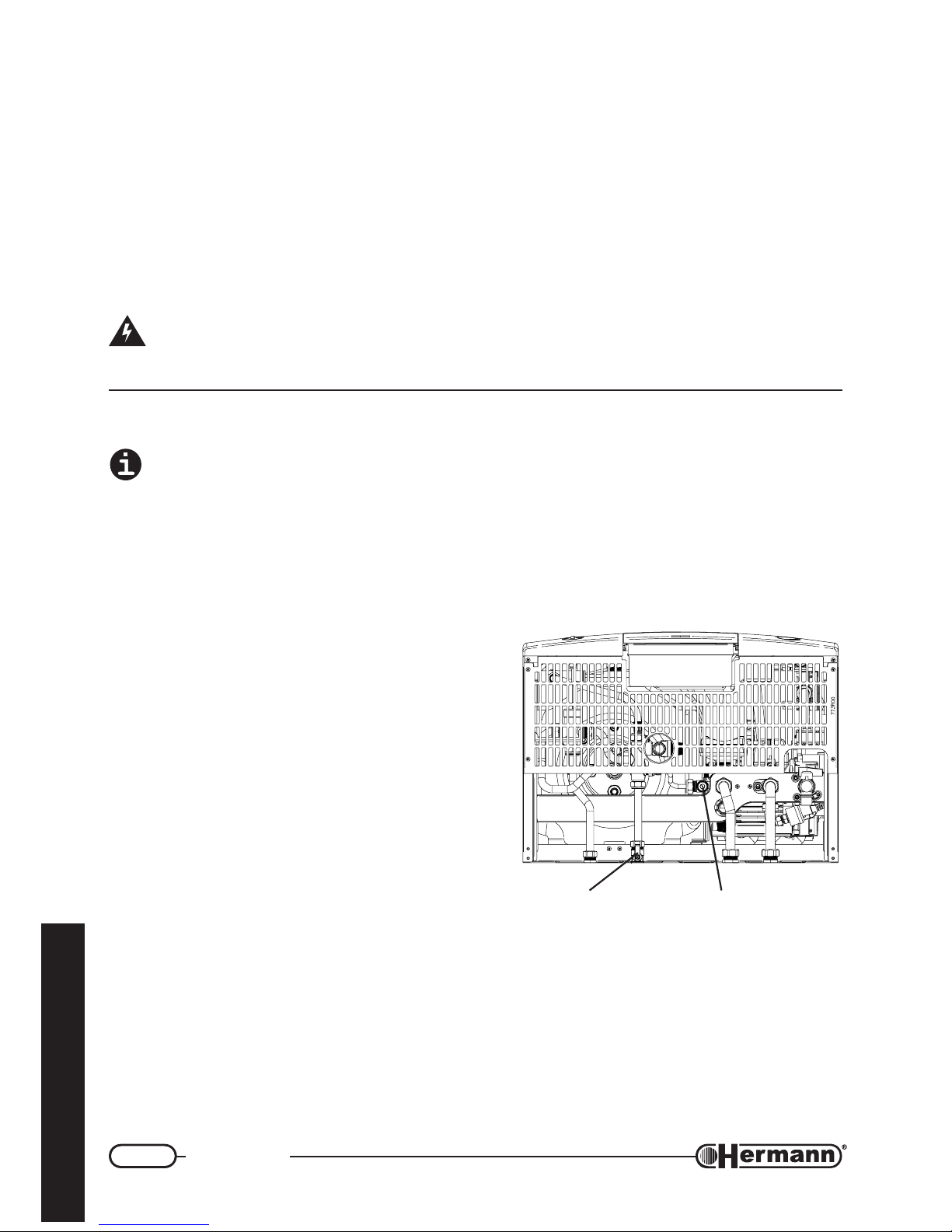
1) Tank filling:
• open a hot water tap;
• slowly open the boiler’s cold water inlet tap
(ref. figure beside);
• when only water flows out of the hot water
tap, close it.
2) Heating system filling (with water):
• open the radiators venting devices;
• gradually open the heating system filling tap
(ref. figure beside), checking the correct
functioning of automatic venting devices,
eventually installed;
• close the radiators venting devices as soon
as water flows;
• Make sure that pressure gauge reaches the optimal value of 1÷1.5 bar (minimum: 0.5
bar);
• close the water supply valve and bleed each radiator.
BOILER BOTTOM VIEW
HEATING SYSTEM
FILLING TAP
COLD WATER
INLET TAP
Page 13

13
Installation
for the technician
Gas connection
Boiler installation must be carried out from a qualified technician, [as indicated by the Law XXXXX]
because an incorrect installation can cause damages to people, animals or things, for which the
manufacturer cannot be held responsible.
Verify what follows:
a) cleaning of all system gas pipes in order to avoid the presence of residual combustion products
that could compromise the correct boiler functioning;
b) gas line and ramp conformity with laws and rules actually in force (Laws UNI-CIG 7129/01 and
7131/99 – DM 12/04/96);
c) internal and external tightness of the gas system and connections;
d) supply pipe must have a section greater than or equal to the boiler one;
e) supply gas must correspond to the one for which the boiler has been regulated; otherwise, call
[an HERMANN Servicing Centre] [a qualified technician] for gas conversion;
f) an interception valve must be installed upstream the appliance;
Open the meter valve and purge the air that is inside the system pipes (including all the appliances).
While connecting gas inlet pipe of the boiler to the pipe coming from gas network, it is
MANDATORY to insert a TIGHT GASKET, whose dimensions and material must be
adequate. Connection is NOT suitable for hemp, teflon strip or similar materials.
Using LPG, it is absolutely necessary to install a pressure reducer upstream the boiler.
Due to various installation possibilities, the gas cock supplied with Standard Connections Kit for
SUPERMASTER boilers has a simple male Ø ½” connection, facing the rear of the boiler. No gas
pipes are supplied.
Page 14
14
Installation
for the technician
Electrical connections
The link of the room thermostat works with a safety extra low voltage (SELV); connect it to
the voltage free terminals of the room thermostat/cronothermostat. On NO account must
any electrical voltage be applied to these terminals.
The boiler must be connected to an electrical line of 230V-50Hz, respecting the polarities L-N (LiveNeutral) and the earth connection.
PLACE UPSTREAM THE BOILER A DOUBLE POLE SWITCH.
The double pole switch must have a minimum contact separation of 3 mm on each pole. For the
general electrical supply of the appliance, the use of adaptors, multiple taps and extensions is not
allowed.
If the supply cable must be replaced, use one of the following wire types: H05VVF or H05-VVH2-F.
It is mandatory the earth connection in accordance with the rules actually in force. To replace
the cable, release the cable fastener placed on the frame of the hydraulic connections, open the
back cover of the control panel and disconnect it from the terminals. Install the new cable working
in the reverse way. It’s IMPORTANT to lock tha cable in the cable fastener placed on the frame of
the hydraulic connections.
Electrical safety of the appliance is only achieved when it is well connected to an
efficient earthing system, executed as indicated by the safety rules actually in force.
A qualified technician must check that the electrical system is in line with the maximum power
allowed by the boiler, indicated on the data plate, with particular attention to the cables section.
Remark: HERMANN Ltd. declines any responsibility for damages to persons, animals or
things caused by the non-connection of the boiler earthing and by failure to comply with
the rules.
Page 15
15
Installation
for the technician
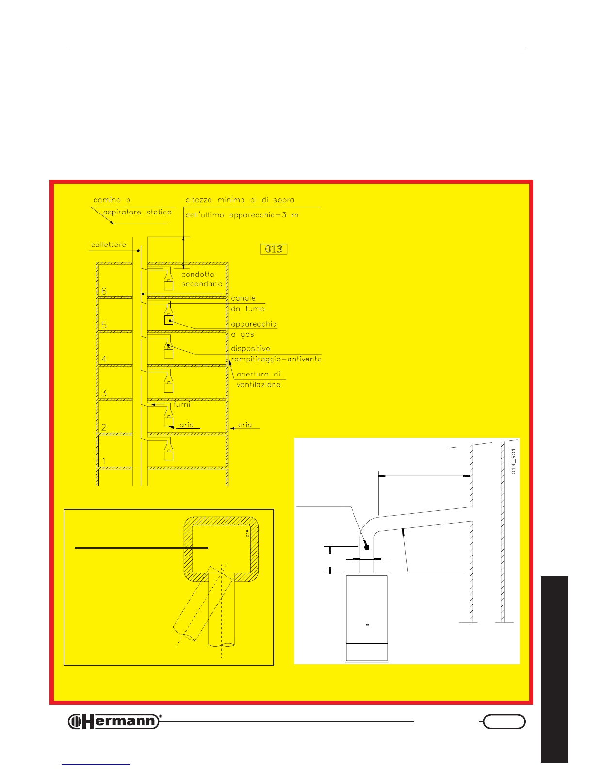
Chimney connections
SUPERMASTER E
(natural draught)
Place here all necessary
advices according to national rules about
CHIMNEY CONNECTIONS of OPEN chamber boilers
FLUE
NO YES
These diagrams are
to explain the most
important ITALIAN
laws concerning
chimney connections
(for EXEMPLE
purpose only)
PRODUCTS TEST POINT
2500 mm MAX
SLOPE
min 3%
2 x d
min
d
Page 16
16
Installation
for the technician
Chimney connections
SUPERMASTER SE
(forced draught)
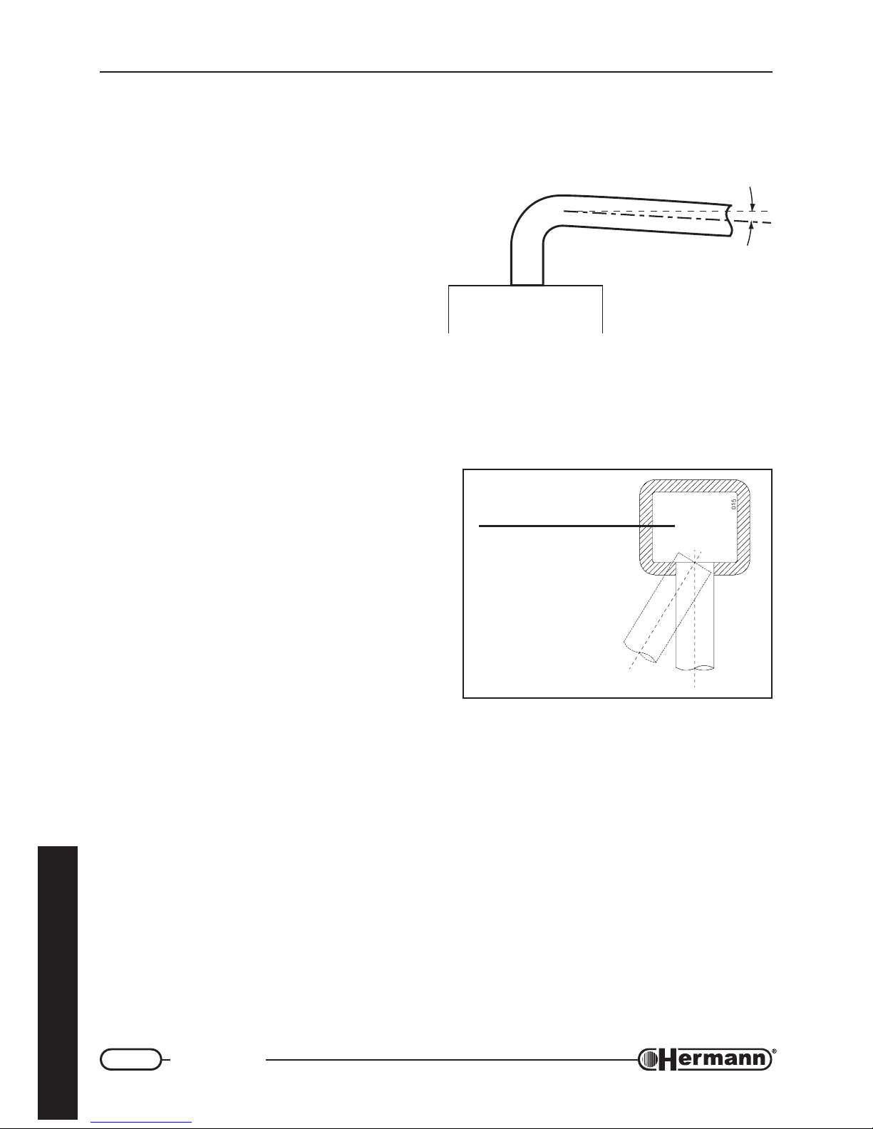
NOTE ON FLUE INSTALLATION
When fitting air inlet and flue outlet horizontal
ducts, it is necessary to make sure there is a slope
of 2÷5% downwards from the boiler to the outside (see diagram). This is essential to guarantee correct boiler operation and reliability. Air inlet and flue outlet terminals should be protected
by suitable approved flue accessories, to avoid
environmental elements penetration.
Place here all necessary
advices according to national rules about
CHIMNEY CONNECTIONS of sealed chamber boilers
FLUE
NO YES
2% ÷ 5%
631R01
Page 17
17
Installation
for the technician
A
B
P
O
N
C
M
F
E
D
I
H
L
G
tupnitaehriehtnognidneped,sreliobthguarddecrofrofslanimreteulffogninoitisoP
gninoitisoplanimreTsecnatsiD
secnailppA
*Wk4morf
Wk7ot
mm
.nim
Wk7morf
Wk61ot
mm
.nim
Wk61morf
Wk53ot
mm
.nim
wodniwarednUA003005006
tnevrianarednUB003005006
rettugarednUC003003003
**ynoclabarednUD003003003
wodniwtnecajdanamorFE004004004
tnevriatnecajdanamorFF006006006
***sepipnoitaucavelatnozirohrolacitrevmorFG003003003
gnidliubehtforenrocamorFH003003003
gnidliubehtfosseceramorFI003003003
roolfrehtonamorfrodnuorgehtmorFL004 0051 0052
yllacitrevslanimretowtneewteBM00500010051
yllatnozirohslanimretowtneewteBN0050080001
ongnivah,ecafrusrehtonagnicafecafrusamorF
.stm3foecnatsidanihtiwslanimretrosgninepo
elohnoitaucaveehtmorf
O005100810002
nihtiwslanimretrosgninepohtiwtub,evobasA
elohnoitaucaveehtmorf.stm3foecnatsida
P005200820003
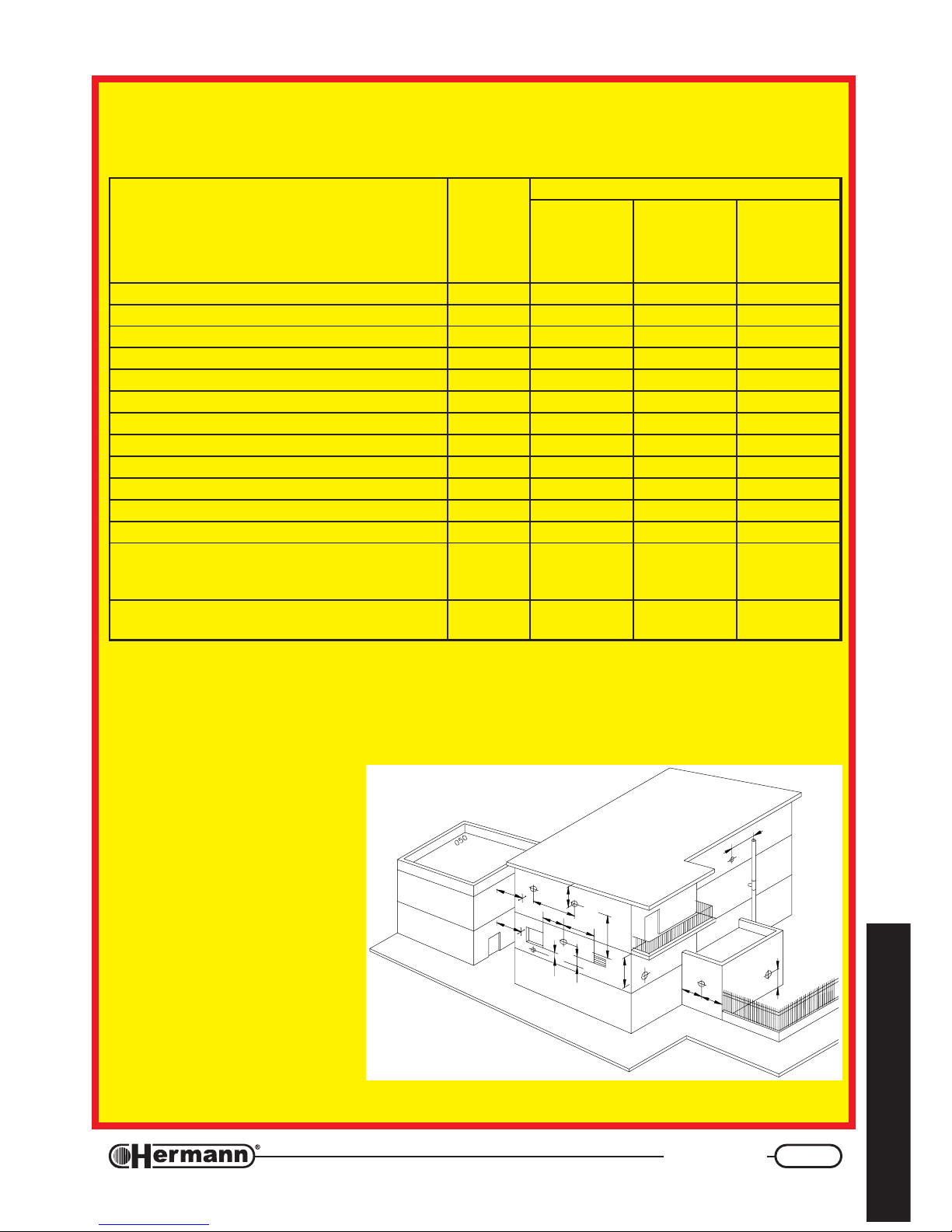
* Appliances with an heat input lower than 4 Kw are not subjected to any limitation for the terminals
positioning, except for the points O and P.
** The terminals under a practicable balcony must be positioned in such a way that the total flue run, from
the terminal outlet to its own outlet from the external balcony perimeter, included the height of the
eventual protection banisters, is no lower than 2000 mm.
*** In the terminal positioning, it will
be necessary to keep
distances not inferior to 500
mm. in case of close proximity
to materials sensible to the
combustion products action
(e.g., plastic gutters and
downpipes, wood projections
and so on), unless adequate
measures of protection have
been adopted.
The terminals must be
designed in such a way that the
combustion products flow is as
much as possible ascensional
and protected from the temperature effects.
In case of evacuation to wall, the positions indicated in the following drawing and table must be
respected:
Page 18
18
Installation
for the technician
High capacity fan
SUPERMASTER 24 SE
For SUPERMASTER 24 SE (forced draught) it is possible to install, on request, an “high capacity
fan”, allowing an higher length of separate flue systems (see table):
Øtelniria/teltuostcudorpeulfetarapeS mm08
htgneleulfetarapeS m)teltuo02xam(03
nafyticapachgihhtiwhtgneleulfetarapeS
m)teltuo04xam(06
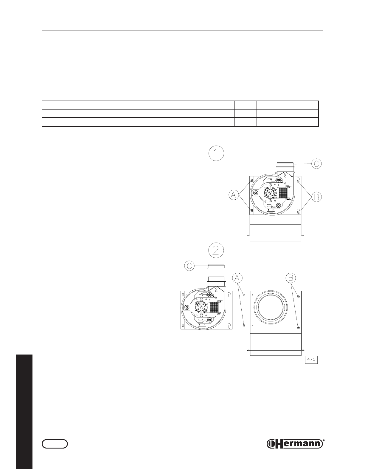
ASSEMBLING INSTRUCTIONS
It is advisable to install the high capacity fan,
before flue kit, avoiding any possible hindrance
during assembling operations.
Provide electrical disconnection of the gas
boiler and remove the sealed chamber closing;
1. Take off screws A, loosen screws B (it is
not necessary to take off screws B, being
the fan bracket provided with button-holes)
and remove the standard fan,
disconnecting its cables for electrical
supply; remove the flue pressure sensor.
2. Remove gasket C from standard fan and
insert it on high capacity fan; install the
flue pressure sensor, respecting its
previous position.
Install the high capacity fan, connect the
cables for electrical supply, tighten screws B
and reinsert screws A.
Reassemble the sealed chamber closing.
Page 19
19
Installation
for the technician
CSCA45CS 135
m
i
n
.
3
0
0
CA45
1
3
0
ø
8
0
ø
8
0
1
3
0
CSCA
759_1_R00
1
3
0
1
3
0
ø
8
0
ø
8
0
1
3
0
1
3
0
ø
8
0
ø
8
0
C
S
1
3
8
5
ø125
1
3
0
CA
45
ø
8
0
ø80
1
3
8
5
ø125
ø80
ø80
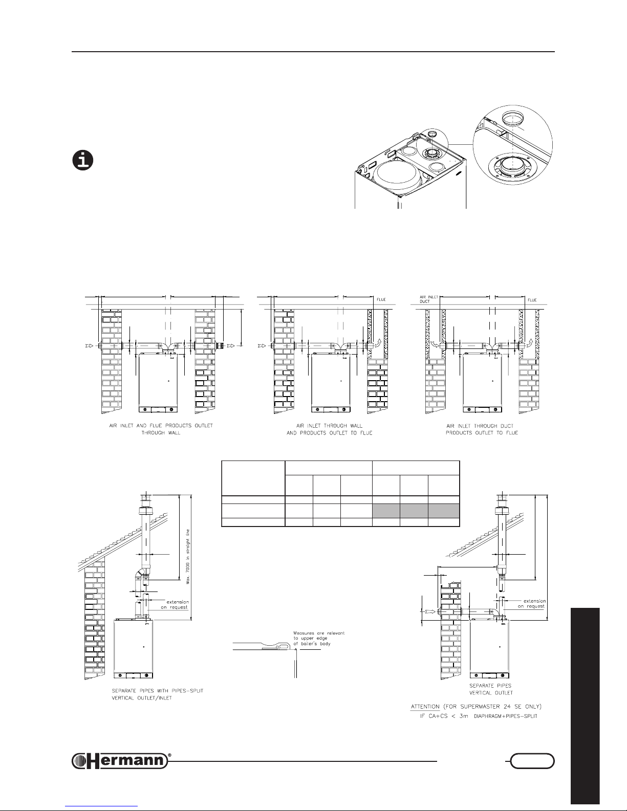
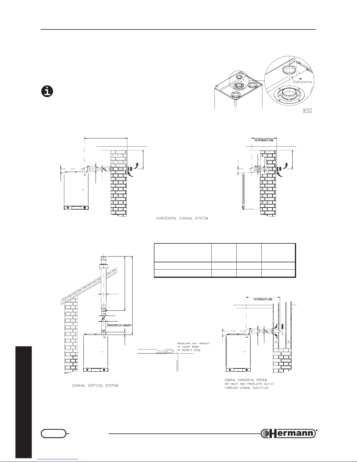
Flue systems
SUPERMASTER SE
AIR INLET AND PRODUCTS OUTLET THROUGH
SEPARATE PIPES
Attention: see table and, if required, install the
diaphragm supplied with the gas boiler, as
indicated in the figure besides (any additional 90°
bend = 0.5 linear meters, 45° bend = 0.25
meters).
ledoM
stcuddetarapeS
rettilpSsepiPhtiW
.noitcennoclaixaocno
SC+AC
xam÷nim
)m(
SC
xam
)m(
mgarhpaiD
otpu
)m(SC+AC
SC+AC
xam÷nim
)m(
SC
xam
)m(
mgarhpaiD
otpu
)m(SC+AC
ES42RETSAMREPUS03÷2028 41÷231ON
ES42RETSAMREPUS
nafyticapachgihhtiw
06÷1304ON
ES03RETSAMREPUS61÷201SYAWLA01÷27ON
7
5
8
_
R
0
0
Diaframma
Page 20
20
Installation
for the technician
A
9
0
LO
IN STRAIGHT LINE
m
i
n
.
3
0
0
A
9
0
LO
m
i
n
.
3
0
0
SS
ø
6
0
ø
1
0
0
ø125
ø60
ø100
1
2
9
5
7
0
L
V
i
n
s
t
r
a
i
g
h
t
l
i
n
e
ø
6
0
ø
1
0
0
760_1_R00
LO
9
0
ø
6
0
ø
1
0
0
ledoM
OL
xam÷nim
)m(
VL
xam÷nim
)m(
mgarhpaiD
aot
)m(VLroOL
ES42RETSAMREPUS 4÷5,0 5÷1 2
ES03RETSAMREPUS 3÷1 4÷1 1
Flue sistems
SUPERMASTER SE
AIR INLET AND PRODUCTS OUTLET THROUGH
COAXIAL SYSTEM
Attention: see table and, if required, install the
diaphragm supplied with the gas boiler, as indicated
in the figure besides (any additional 90° bend = 1
linear meter, 45° bend = 0.5 meters).
Page 21
21
Regulation and servicing
for the technician
INSTRUCTIONS FOR FIRST IGNITION,
REGULATION AND MAINTENANCE
ATTENTION: the operations described below
must be carried out only by qualified personnel
[authorized by HERMANN].
When regulation/measuring is over, remember
to tighten pressure tapping point screws and
check for gas leaks!
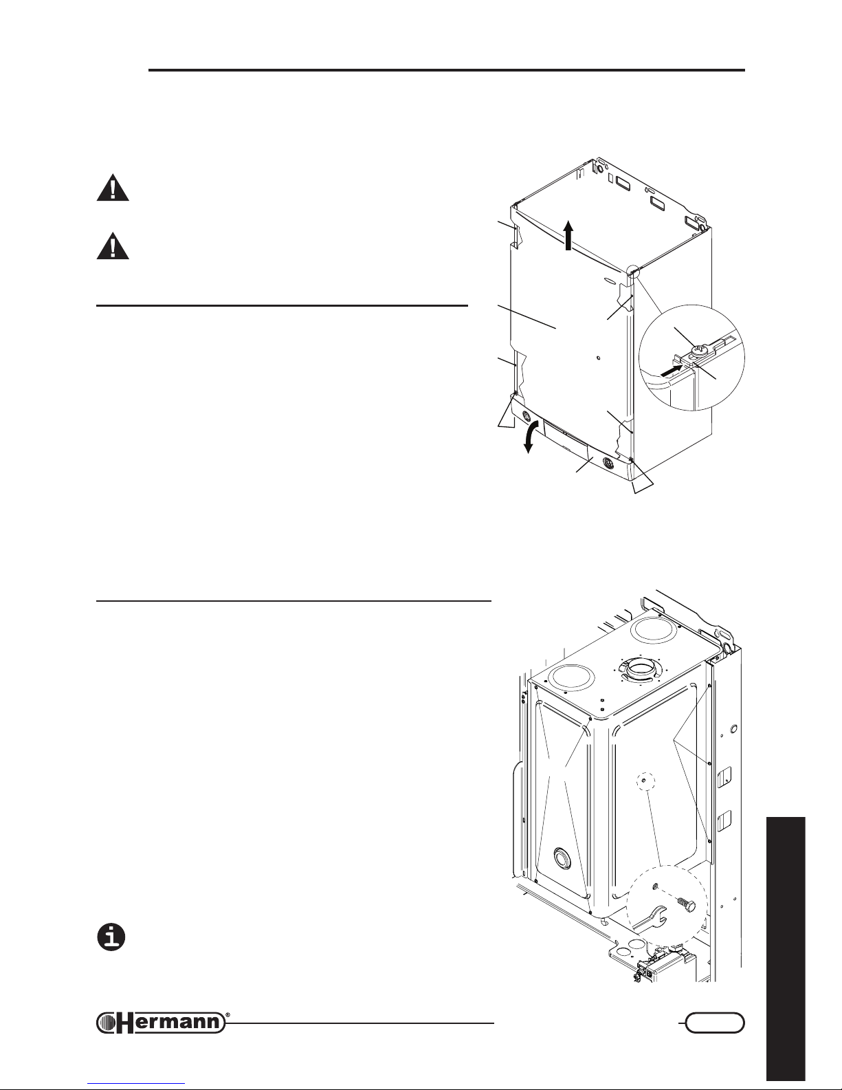
Access to the regulation
devices
1. Unscrew the screws [1] and let the catches slide [2]
in order to release the front casing [3];
2. Push the front casing [3] upwards and remove it;
3. Unscrew the screws [4] and overturn downwards the
control panel [5];
4. After the regulations, close the boiler repeating everything in the other sense, paying attention
to insert the flexible shaft of the DHW temperature knob in its clutch on manual mixing valve.
Hook the frontal casing to the heads of the four screws [6] (which must not be released) and
remember to stop it through the catches [2] and through the screws [1].
Opening of the sealed
chamber
In order to execute all the operations for the cleaning and
maintenance of the boiler it is necessary to put the closing of
the sealed chamber down, making the following actions:
— Release the screws [1]
— Release the screw with hexagonal head [2] (only model
30 SE)
— Pull out the closing of the sealed chamber.
When all the operations have been done, put the closing of
the sealed chamber up making the previous actions in the
opposite order.
ATTENTION: it is important to put up ALL the screws
for the fixing of the closing in order to ensure the seal
of the sealed chamber and avoid eventual vibrations
and noise.
3
774R01
6
6
5
6
6
4
1
2
4
1
1
2
7
8
0
R
0
0
Page 22
22
Installation
for the technician
1
2
3
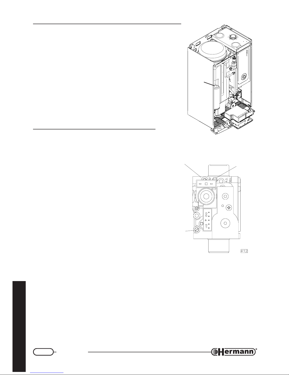
GAS VALVE SIT 845
1 = Pressure tapping point
for gas outlet
2 = Pressure tapping point
for gas inlet
3 = Vent (mod. SE)
Prefilling of the DHW expansion
vessel
— Measure the well pressure or get informed about its value;
— Close the tap installed on the boiler cold water inlet;
— Open the hot water tap in order to unload the remaining
pressure, and close it;
— Release the protection tap [1] of the expansion vessel’s loading
inlet and load the vessel with air with the same pressure of the
water network;
— Reopen gradually the installed tap on the boiler cold water
inlet.
Preliminary GAS
checkings
All boilers are tested and factory set during
manufacture; however, it is advisable to check that the
gas type and the burner pressures are correct. On the
contrary, follow the procedures described in this section.
To make burner pressures checking, insert pressure
gauge sensors in the gas valve pressure tapping points
(see figure).
Remark: In order to check that pressure and gas input
are enough to guarantee the correct functioning of
the appliance , make measurements while burner
is on.
1
Page 23
23
Regulation and servicing
for the technician
C
A
B
MODULATOR DETAILS
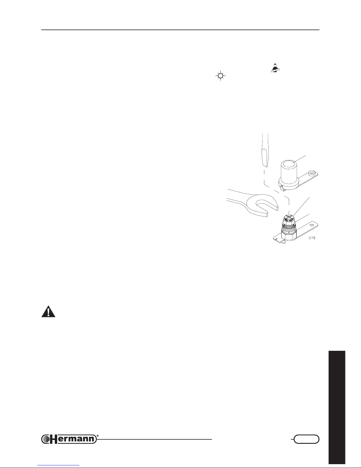
Gas valve pressure regulation (MAX-MIN)
— Check that the inlet pressure is correct for the type of gas supplied;
Bring and keep the Summer/Winter Selector in the position Chimneysweeper
for at least 3
seconds, then let the selector return in the position Summer
. The green lamp flashes rapidly
and the burner ignites at the maximum outlet, for a period sufficient to make the checks and the
measurements. The produced heat is carried off by the heating system;
Wait for at least 10 seconds and check that the pressure
corresponds to the highest value indicated in the “Power
Pressure” table of the specific model. If it is necessary a
correction of the regulation, (referring to the figure), make the
following actions:
• make sure that the modulation coil is energised;
• remove protection cap “C”. On “SE” models, take off
the silicon tube from the “VENT” on the gas valve
(item 3 in the figure);
• adjust maximum pressure by turning knob “B”, with a
10 mm. spanner. Clockwise to increase, counterclockwise to decrease;
• remove electrical connector on modulation coil;
• keeping knob “B” locked, adjust minimum pressure
unscrewing screw “A” very slowly, using a 4 mm
screwdriver;
• refit electrical connector of the modulator and check
settings;
• turn off the burner turning the selector Summer/Winter in the central position. The green
lamp flashes slowly.
• On “SE” models, refit silicon tube in the “VENT” on the gas valve (item 3 in the figure).
ATTENTION: after this operation, the value indicated by pressure gauge could decrease
due to pressure compensation. This is normal and does not require any adjustment.
Important: lock the adjustment device after any setting operation.
Page 24
24
Regulation and servicing
for the technician
Slow opening regulation
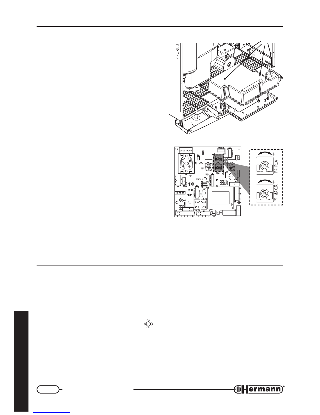
To adjust the slow opening, proceed as follows:
— switch off the boiler;
— release the screws [1] (see figure) and remove
the back closing of the control panel;
REMARK: you will have 8 seconds for the regulation
of the slow opening pressure, and after these
8 seconds the pressure of the burner increases
to the highest value. To increase this period of
time to 30 seconds, turn the trimmer P1 MAX.R.
completely in anticlockwise sense (it will be
necessary to regulate consequently the Max
Heating Power).
— turn on the boiler and open a cold water tap, the
burner will turn on allowing to check the pressure
of slow opening. In case the values are different
from:
Nat. gas: mod. 23 E: 3,5 mbar (36 mm w.g.)
mod. 28 E: 5 mbar (51 mm w.g.)
mod. 24 SE: 7 mbar (71 mm w.g.)
mod. 30 SE: 5 mbar (51 mm w.g.)
L.P.G.: mod. 23 E: 8 mbar (82 mm w.g.)
mod. 28 E: 8 mbar (82 mm w.g.)
mod. 24 SE: 14 mbar (143 mm
w.g.)
mod. 30 SE: 14 mbar (143 mm w.g.)
turn the trimmer P4 RLA (in clockwise sense to increase the pressure and in anticlockwise
sense to decrease the pressure) till the achievement of the correct value.
Regulation of MAX heating power
The maximum heating output must be set in accordance with the system requirements (stated in
the project). The gas pressure values related to the different outputs are indicated in the table
“BURNER PRESSURES”. To adjust the burner pressure proceed as follows referring to the figure:
— Remove the back closing of the control panel releasing the screws [1] (see figure).
— Set Summer/Winter selector to Winter
position and adjust the eventual room thermostat to
a temperature value higher than the present one.
— When the burner is turned on (wait the end of the climbing ramp which lasts about 1 minute)
check the value of the maximum gas pressure through the pressure gauge.
— Adjust pressure turning round the potentiometer P1 MAX. R. until reaching the required value.
— Close the control panel.
1
704_R01
Page 25
25
Regulation and servicing
for the technician
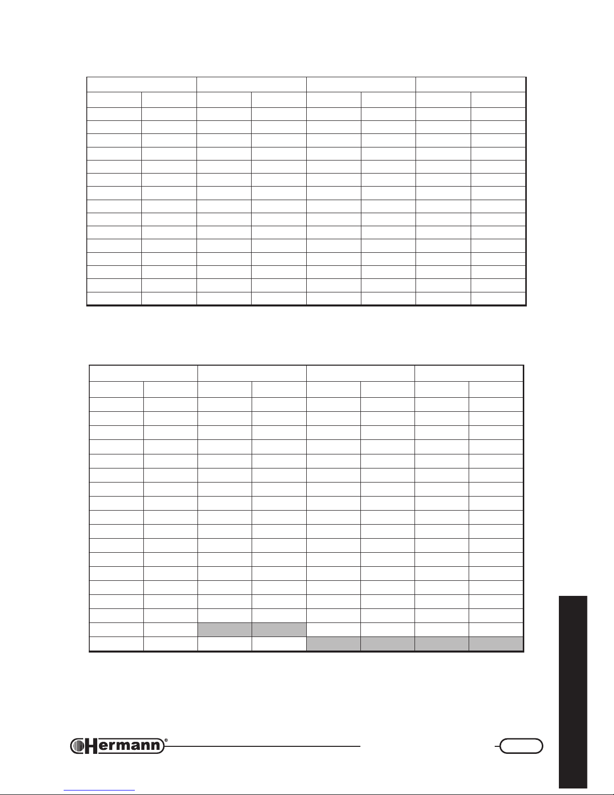
BURNER PRESSURES for SUPERMASTER 23 E
TUPTUOTAEH02GSAGLARUTAN03GENAHTUB13GENAPORP
Wkh/lackrabmHmm
2
OrabmHmm2OrabmHmm2O
1.9.NIM08772.2228.4948.494
0100687.2728.5959.506
1106492.3230.7172.747
21023017.3832.8487.888
31081114.4446.9792.01401
41040210.5150.112110.21221
51009217.5855.217219.31141
61067314.6561.414419.51261
71026411.7378.511611.81581
81084519.7185.719715.02902
91043617.8983.917910.32532
02002716.9892.127127.52362
12060814.017012.327326.82292
22029813.116112.527527.13323
1.32.XAM068913.215214.729720.53753
BURNER PRESSURES for SUPERMASTER 28 E
TUPTUOTAEH02GSAGLARUTAN03GENAHTUB13GENAPORP
Wkh/lackrabmHmm
2
OrabmHmm2OrabmHmm2O
4.11.NIM00898.2925.5655.565
21023011.3131.6262.636
31081115.3631.7273.747
41040210.4141.8385.878
51009216.4743.9599.9101
61067311.5255.017014.11611
71026417.5857.110219.21231
81084513.6461.313316.41941
91043619.6075.418415.61861
02002715.7779.512614.81881
12060812.8384.718715.02902
22029818.8090.914917.22132
32087915.9796.020120.52552
42046022.014013.228225.72082
52005129.011110.425421.03703
62063226.119118.523628.23533
1.72.XAM00332
7.723828.53563
5.72.XAM096328.21131
Page 26
26
Regulation and servicing
for the technician
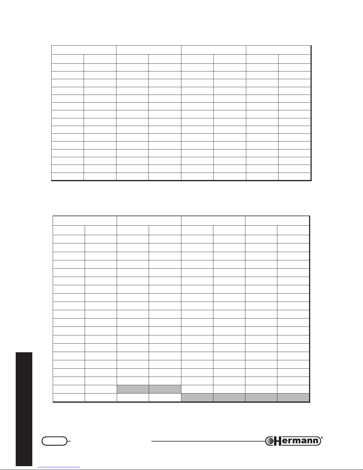
BURNER PRESSURES for SUPERMASTER 24 SE
TUPTUOTAEH02GSAGLARUTAN03GENAHTUB13GENAPORP
Wkh/lackrabmHmm
2
OrabmHmm2OrabmHmm2O
9.8.NIM08672.2229.4059.405
0100687.2821.6262.636
1106492.3332.7475.767
21023018.3934.8689.819
31081114.4548.90014.01701
41040210.5151.114111.21421
51009217.5856.218219.31241
61067314.6561.414419.51261
71026411.7277.510610.81381
81084518.7083.717712.02602
91043616.8780.914915.22032
02002714.9697.022120.52552
12060812.014015.220326.72282
22029810.112113.428424.03013
6.32.XAM062023.215212.727725.43253
BURNER PRESSURES for SUPERMASTER 30 SE
TUPTUOTAEH02GSAGLARUTAN03GENAHTUB13GENAPORP
Wkh/lackrabmHmm
2
OrabmHmm2OrabmHmm2O
0.11.NIM05491.2124.4544.454
21023015.2522.5353.545
31081119.2031.6263.646
41040213.3430.7273.757
51009218.3930.8285.878
61067313.4441.9397.999
71026418.4942.014011.11311
81084513.5454.116115.21821
91043619.5066.219211.41441
02002715.6669.312418.51161
12060811.7272.515515.71971
22029817.7976.610714.91891
32087914.8681.814814.12812
42046021.9296.910025.32042
52005128.90011.126127.52362
62063225.017018.222321.82782
72022322.114114.429426.03213
82080420.212211.626622.33833
1.92.XAM00052
8.724828.53563
5.92.XAM004521.31431
Page 27
27
Regulation and servicing
for the technician
Changing Gas type
ATTENTION: the operations described below must
be carried out only by qualified personnel
[authorized from HERMANN Ltd].
For gas conversion, use the nozzles supplied by boiler
manufacturer only.
CONVERSION FROM NATURAL GAS TO L.P.G.
Using LPG, it is absolutely necessary to install a
pressure reducer upstream the boiler.
1. Disconnect the boiler from the electrical supply.
2. On “SE” models, open sealed combustion chamber.
3. Remove pipe between gas valve and injectors bar.
4. Remove injectors bar and replace injectors with the ones
suitable for L.P.G., using a 7 mm. spanner (see figure
“BURNER”). Reassemble injectors bar and pipe,
replacing gaskets. On “SE” models, close sealed
combustion chamber;
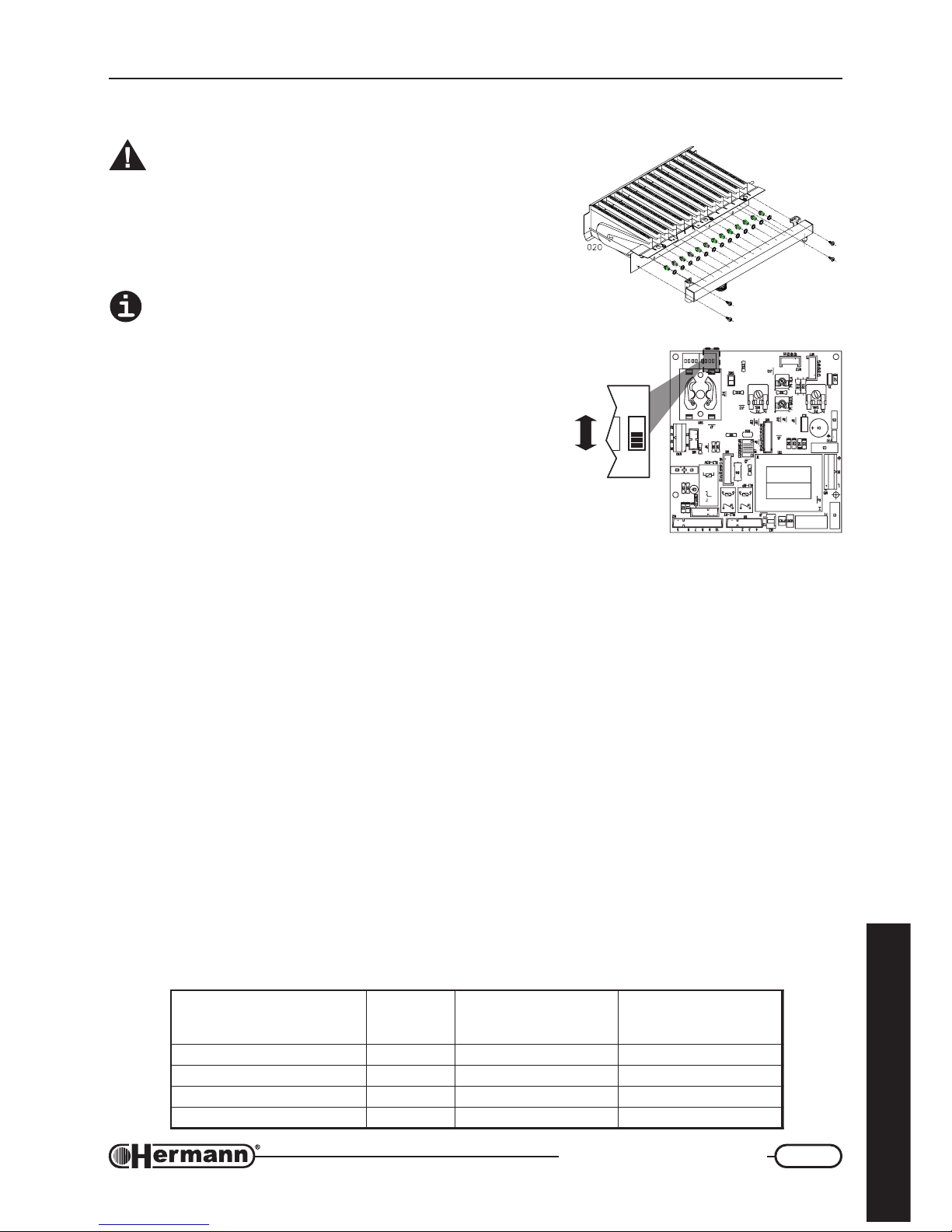
5. Remove the cover of the control panel and move the first microswitch of SW3 (on the right) in
the position ON, indicated in the figure with “GPL”.
6. check that pressure upstream the boiler is: Buthane = min.25 - max.35 mbar or Propane =
min.25 -max.37 mbar.; check for gas leaks;
7. repeat following regulations: Domestic Water Output (max. and min.), Slow Opening Pressure
and Heating Output, carefully reading the instructions given in the previous pages.
CONVERSION FROM L.P.G. TO NATURAL GAS
1. Disconnect the boiler from the electrical supply.
2. On “SE” models, open sealed combustion chamber.
3. Remove pipe between gas valve and injectors bar.
4. Remove injectors bar and replace injectors with the ones suitable for Natural Gas, using a 7
mm. spanner (see figure “BURNER”). Reassemble injectors bar and pipe, replacing gaskets.
On “SE” models, close sealed combustion chamber;
5. Remove the cover of the control panel and move the first microswitch of SW3 (on the right) in
the position OFF, indicated in the figure with “MET”.
BURNER
LEDOM
rebmuN
selzzonfo
rofØselzzoN
02GSAGLARUTAN
)mm001/1(
rofØselzzoN
13G/03G.G.P.L
)mm001/1(
E32RETSAMREPUS3102157
E82RETSAMREPUS4152167
ES42RETSAMREPUS3102157
ES03RETSAMREPUS4103187
705_R01
1
SW3
ON
MET
GPL
Page 28
28
Regulation and servicing
for the technician
6. check that pressure upstream the boiler is: Natural Gas min.17-max. 25 mbar; check for gas
leaks;
7. repeat following regulations: Domestic Water Output (max. and min.), Slow Opening Pressure
and Heating Output, carefully reading the instructions given in the previous pages.
Combustion check
The boiler has a “CHIMNEYSWEEPER” function which draws the ignition of the burner to the
highest power (not modulated) without working on the room thermostat.
— Arrange the instruments for the combustion check;
— bring and keep the selector Summer/Winter in the “Chimneysweeper”
Position for at least 3
seconds, then let the selector return in the Summer Position. The green lamp flashes
rapidly and the burner ignites at the maximum output, for a period sufficient to make the cheking
and the measurements. The produced heat is carried off by the heating system;
— to turn off the burner, turn the selector Summer/Winter in the central (0) position. The green
lamp flashes slowly.
REMARK: the burner will turn off automatically at the achievement of the system highest tempera-
ture and, however, after 15 minutes.
Draining heating system
and tank serpentine
— To correctly unload both the heating system and
the tank’s serpentine, the boiler must be switched
off and it is necessary to manually set three-way
valve in middle position as described here below:
• three way valve (item 1 in figure) must be
initially in “sanitary” mode (manual control
spindle in position “S”). If it were in “R”
position turn the Summer/Winter selector
in Summer
position and wait until the
lever moves on S position;
• switch boiler off and turn off its electrical power supply;
• manually push spindle towards middle position, where it can
be blocked pushing towards inside (position “C”).
— Connect a rubber pipe to the heating system draining tap terminal
(item 2 in figure);
— put the other end of the pipe in a suitable drain or sink;
R
S
C
132
Page 29

29
Regulation and servicing
for the technician
— open draining tap by turning its hexagonal nut anticlockwise;
— when water pressure is COMPLETELY drained, you can open radiators air vents, to allow air
inlet and complete plant draining;
— when everything is over, close the draining tap and ait vents.
Draining the tank
— Close the tap installed on the boiler cold water inlet;
— insert a rubber pipe on the tank outlet tap;
— connect the other side of the rubber pipe to a suitable outlet;
— open the tap turning in anticlockwise order the grained ring;
— when this operation is finished close the outlet tap turning the ring in clockwise order.
Check and replacement
of the magnesium anode
To protect the tank from the corrosion attacks it is necessary to check every 6 months the
magnesium anode and replace it if it’s damaged.
— Unload the tank completely (see previous paragraph);
— release the hexagonal head of the anode which is placed in the middle of the inferior flange of
the tank. Take it out, check it and if it is necessary replace it;
— install the anode, fill and put in pressure the tank (see paragraph “System Filling”) and verify the
lack of water losses.
Page 30

30
Regulation and servicing
for the technician
Hydraulic section
STORAGE TEMPERATURE REGULATION
The boiler supplies hot water with constant temperature thanks to a mixing system between the hot
water coming from the cold water heater. The normal temperature regulation of the outlet water
must be made through the knob
on the control panel.
There is also a secondary regulation which changes the temperature of only the heater.
This regulation is made in the firm for the best functioning of the boiler and it should
not be modified. A too low regulation doesn’t guarantee the correct hot water temperature
control, whether a too high temperature could bring to big scale formations if the water is
very strong and, consequently to the need of frequent cleaning of the exchange serpentine.
So, it is suggested to intervene with big caution on this regulation and to intervene only in the cases
of very strong types of water.
Remark: it is possible to set this regulation on minimum to make the boiler work in “room anti-
freeze” mode during an inactivity period, in the case that is installed a common room thermostat
or chronothermostat featuring this possibility (see also “Boiler inactivity”). With this setting on
minimum, the boiler will anyway check the temperature of the stored water, keeping it above the
freezing temperature. Remember to put this setting back to the original position at the end of
the inactivity period.
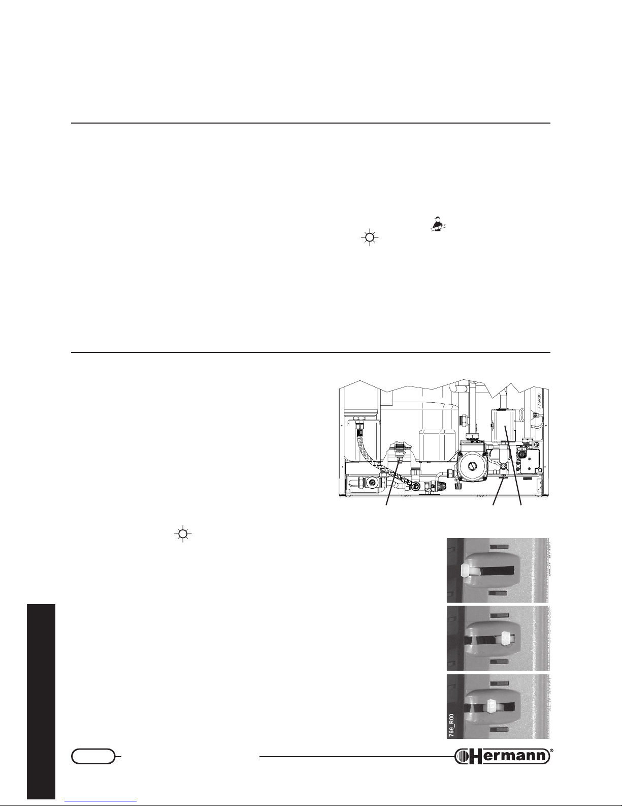
— Open the wicket of the control panel and take the protection plug on the right side of the knob ,
without turning it, grasping the small tongue with the nippers;
— turn the staff in clockwise sense to increase the storage temperature and anticlockwise to
decrease it. In every case do not overcome the limit MIN and MAX. The best firm set up
corresponds to the middle position between the limits MIN and MAX.
Page 31
31
Regulation and servicing
for the technician
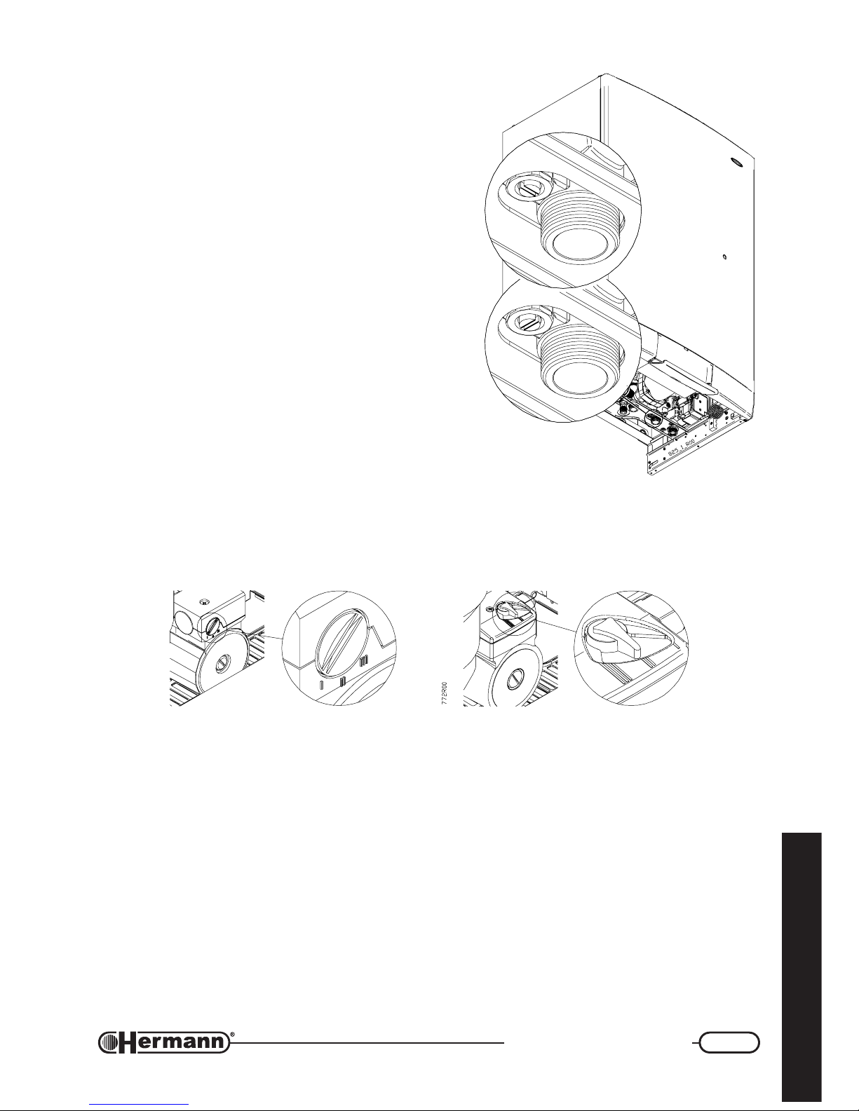
EXCLUSION OF AUTOMATIC BY-PASS
The boiler is factory equipped with an automatic Bypass valve. When it’s completely open it guarantees a
flow that’s enough for boiler’s normal work, without
causing the intervention of safety devices. It’s possible,
anyway, to exclude it as follows:
1. Turn off the boiler by turning the Summer/Winter
selector on central (0) position.
2. Turn the screw on the By-pass (see picture) until
it’s in the position shown in “B”.
To turn the By-pass back in the original, automatic
working mode, turn the screw until it’s in the position
shown in “A”.
PUMP’S SPEED
The pump has a selector which allows to reduce the
speed, so as to reduce the noise produced by the too
rapid circulation of the liquids in too small heating
systems.
III = Maximum Speed (Firm Set up)
II = Medium Speed
I = Minimum Speed
A
B
Page 32
32
Regulation and servicing
for the technician
Electronical regulation
POSSIBLE REGULATIONS ON THE MAIN P.C.B.
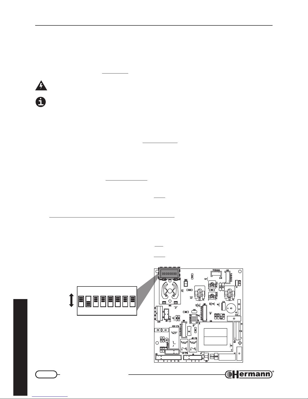
The SUPERMASTER models are equipped with a Microprocessor P.C.B., with a sequence of 8
microswitches (SW3 / 1:8) which allow to make personalizing actions for the boiler’s functioning.
The firm arrangements are
underlined.
Disconnect the power supply before approaching the microswitches. Restore the power
supply only after you have closed the back cover of the control panel.
Moreover, the changes of the microswitches haven’t effect until the boiler is electrically
connected.
SW3 / 1 – Natural gas Functioning = OFF. LPG Functioning = ON. The firm arrangement depends
on the gas type arranged for the boiler. For the GAS TYPE Changing it is necessary to follow
the complete instructions described in the previous paragraph “Changing Gas type”.
SW3 / 2 – Heating Flow Temperature Range:
OFF = normal (+30°C/+80°C); ON = reduced (+25°C/
+45°C). The reduced arrangement is thought for low temperature systems, but the best results
with this type of system are gained with the normal arrangement, using the suitable optional
Low Temperature Kit.
SW3 / 3 – It determines the delay of 3 Minutes, before the new ignition after the overcoming of the
heating set temperature.
OFF = Delay ON (for normal systems or radiators); ON = Delay OFF
(for fan coil systems).
SW3 / 4 – In SUPERMASTER Boilers it must be
OFF.
SW3 / 5 and 6 – Pump Functioning Way in Heating System:
5 OFF – 6 OFF: intermittent for normal applications (with or without delay, see SW3/3)
5 OFF – 6 ON: always turned off (with outside circulators)
5 ON – 6 Unimportant (OFF or ON): always on (for high thermic Inertia systems)
SW3 / 7 – In SUPERMASTER Boilers it must be
ON.
SW3 / 8 – In SUPERMASTER Boilers it must be
OFF.
706_ON7_R00
ON
ON
OFF
SW3
12876543
Page 33

33
Regulation and servicing
for the technician
Warnings for servicing
All servicing operations and gas conversions MUST BE CARRIED OUT BY QUALIFIED
TECHNICIANS, in accordance with the Law n°46 dtd. 05/03/1990 and with the rules
UNI-CIG 7129/92 and 7131/99 and revisions. Moreover, in accordance with art.11 section
4 D.P.R. 412/93 , SERVICING operations must be carried out, at least once a year, by
HERMANN AUTHORIZED SERVICING CENTRES, and must be written in the appliance
booklet, as indicated by the laws UNI and CEI presently in force.
At the end of each heating period, it is necessary to call a qualified technician to check the boiler, in
order to keep the system perfectly efficient.
A careful servicing is always a guarantee of safety and saving.
Normally, it will be necessary to execute the following operations:
— Remove any possible oxidization from burners and electrodes;
— Scale exchangers;
— Check boiler ignition, switching off and operation;
— Check water and gas connections tightness;
— Check gas consumption at the minimum and maximum output;
— Verify that safety devices are correctly working;
— Verify correct functioning of control and adjusting devices;
— Verify periodically good working and efficiency of the combustion product evacuation ducts
and/or devices;
— Check (every 6 months) and when necessary the substitution of the magnesium anode;
— In case of works or servicing of the structures placed near above mentioned ducts and /or
devices and their accessories, switch off the boiler;
— Do not leave any inflammable tanks and/or substances in the installation room;
— Do not clean the room where boiler is installed, while it is working.
— Clean casing with soapy water only. Do not clean casing, other painted or plastic surfaces with
thinner.
— In any case of parts replacement, it is mandatory to use HERMANN original spare parts.
HERMANN declines any responsibility in case of non-original spare parts utilization.
Once all servicing operations have been carried out, it is mandatory to write a report for the
user, that should indicate state of the appliance, servicing interventions and eventual advices
and prescriptions.
Page 34
34
Regulation and servicing
for the technician
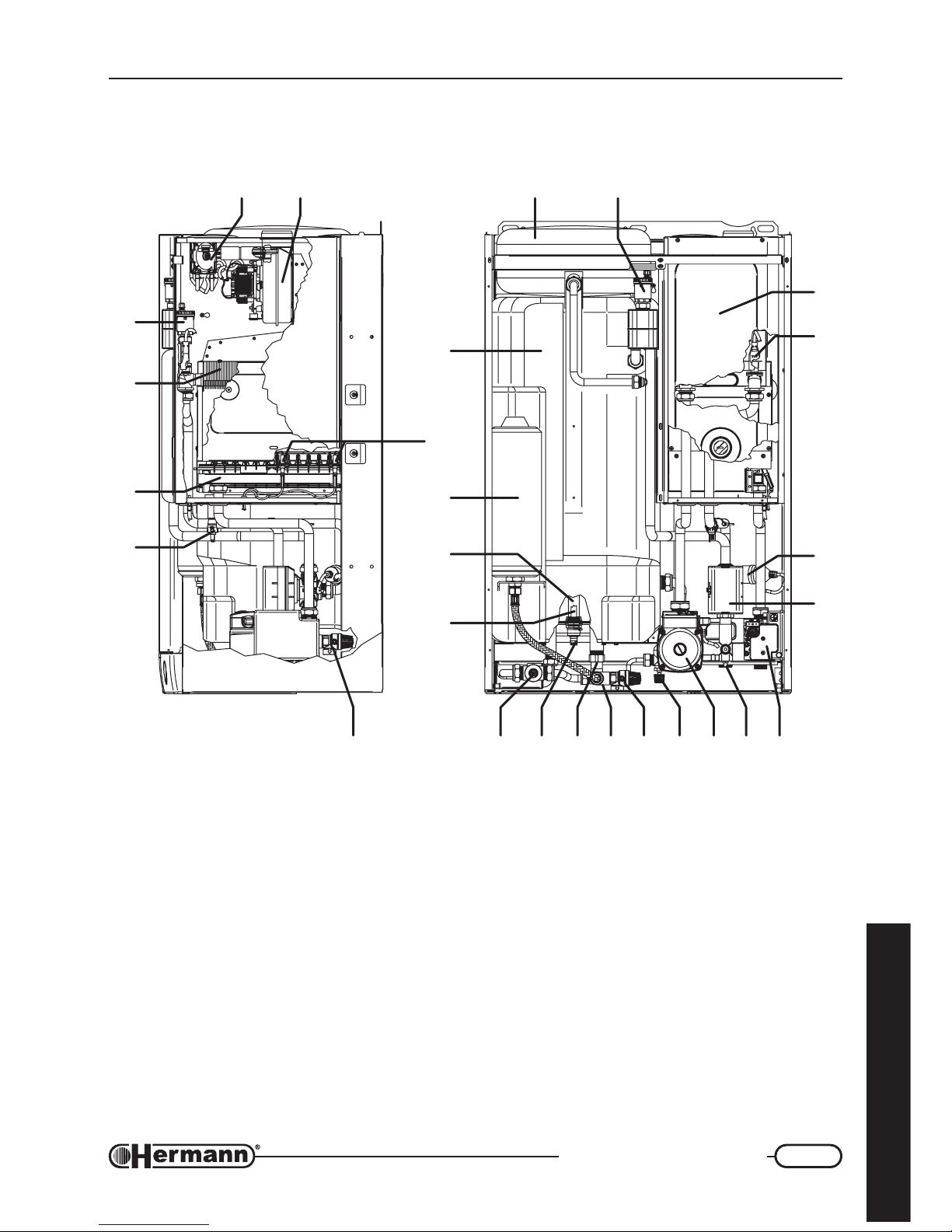
Components of the gas boiler
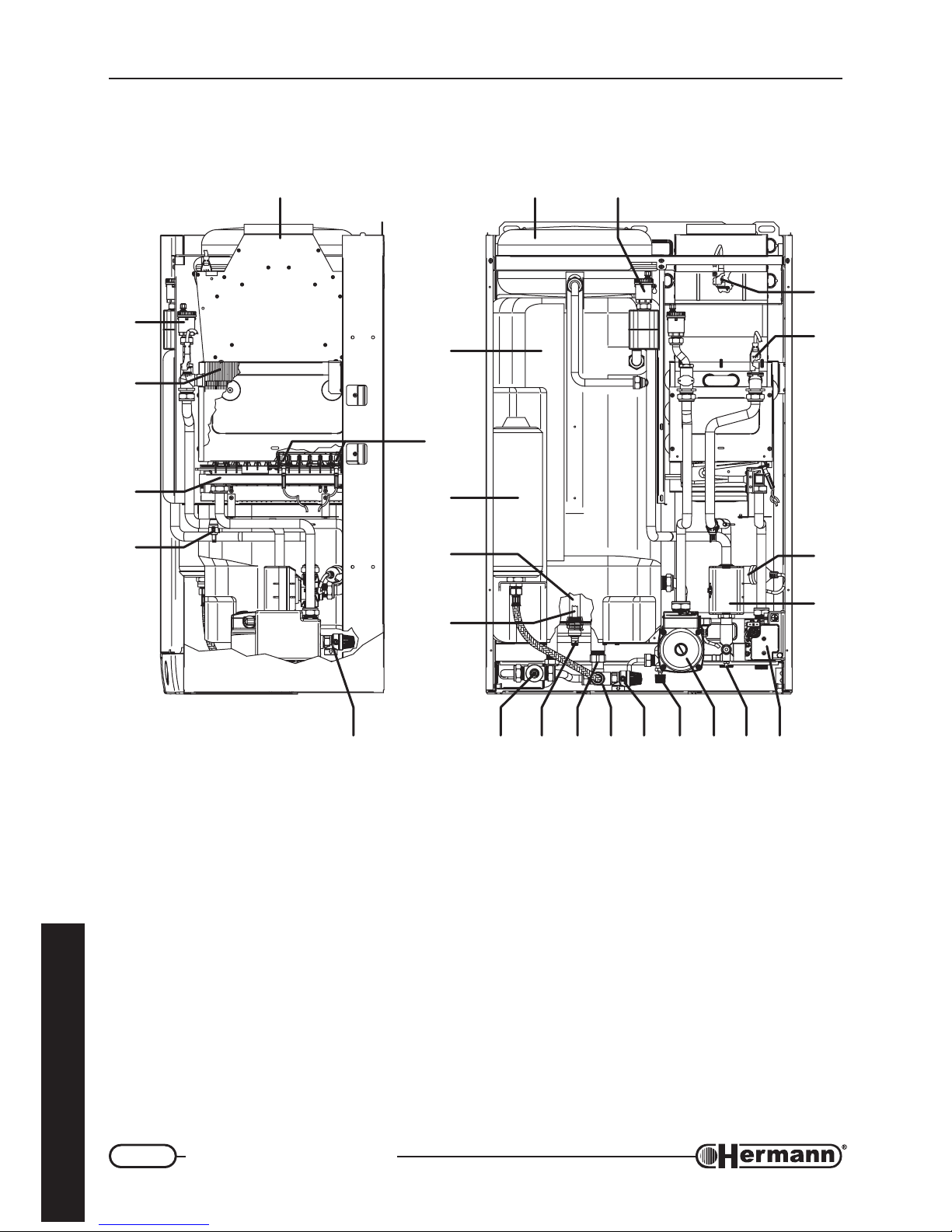
SUPERMASTER 23 E - 28 E
1 Water heater tank
2 Ignition and flame control electrodes
3 DHW expansion vessel
4 Magnesium anode
5 Water heater tank temperature
sensor
6 DHW manual mixing valve
7 Water heater tank outlet tap
8 Litercounter
9 DHW filter
10 DHW Safety valve (8 bar)
11 System filling tap
12 Pump
13 Heating circuit drain tap
14 Gas valve
15 Motorized 3 way valve
16 Loss of water pressure switch
17 Safety thermostat
18 Flue thermostat
19 Automatic air outlet valve (DHW tank)
20 Heating circuit expansion vessel
21 Flue hood
23 Automatic air outlet valve (heating circuit)
24 Primary exchanger
25 Burner
26 Heating system flow temperature sensor
27 Heating circuit safety valve (3 Bar)
2
1
777R00
23
24
25
26
2021 19
3
4
5
15
16
17
18
627 7 8 9 10 11 12 13 14
Page 35
35
Regulation and servicing
for the technician
Components of the gas boiler
SUPERMASTER 24 SE - 30 SE
2
1
778R00
23
24
25
26
202122 19
3
4
5
15
16
17
18
627 7 8 9 10 11 12 13 14
1 Water heater tank
2 Ignition and flame control electrodes
3 DHW expansion vessel
4 Magnesium anode
5 Water heater tank temperature
sensor
6 DHW manual mixing valve
7 Water heater tank outlet tap
8 Litercounter
9 DHW filter
10 DHW Safety valve (8 bar)
11 System filling tap
12 Pump
13 Heating circuit drain tap
14 Gas valve
15 Motorized 3 way valve
16 Loss of water pressure switch
17 Safety thermostat
18 Sealed chamber
19 Automatic air outlet valve (DHW tank)
20 Heating circuit expansion vessel
21 Fan
22 Flue pressure switch
23 Automatic air outlet valve (heating circuit)
24 Primary exchanger
25 Burner
26 Heating system flow temperature sensor
27 Heating circuit safety valve (3 Bar)
Page 36
36
Regulation and servicing
for the technician
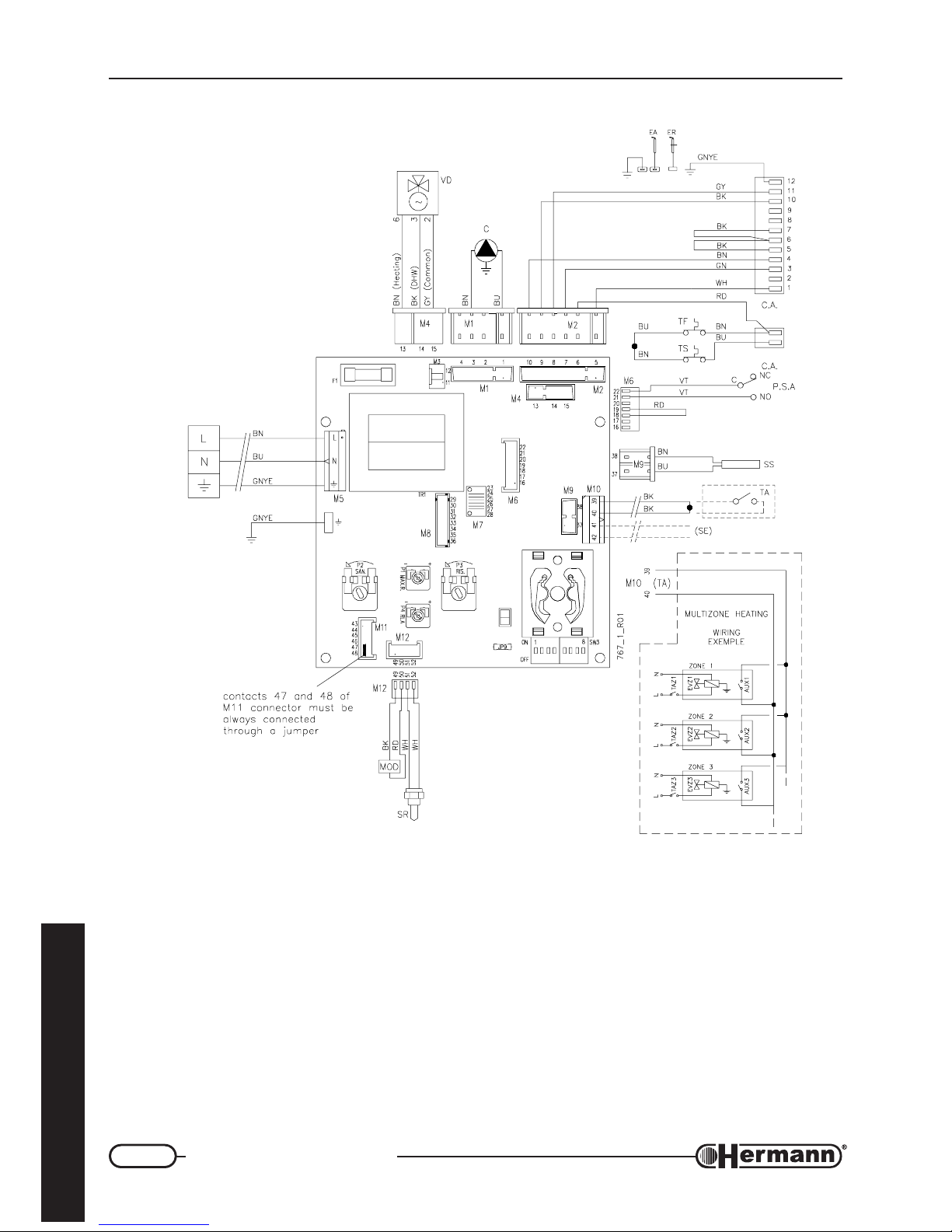
C Pump
CA Ignition and flame control unit
EA Ignition electrode
ER Flame sense electrode
F1 Fuse (2 A)
MOD Modulatore
PSA Low water pressure switch
(contact NA closed = in pressure)
SR Heating NTC sensor
SS DHW storage NTC sensor
TA Voltage-free Contact for Room Thermostat
or Cronothermostat
(for trade) (safety extra low voltage SELV)
TF Flue thermostat
TS Safety thermostat
VD Motorized deviating valve
(SE) Arrangement for external
sensor (optional)
Electric diagram for
SUPERMASTER 23 E - 28 E
EVZ1/2/3… Electrovalve
zone 1/2/3…
AUX1/2/3… Auxiliary contact for
EVZ1/2/3…
TAZ1/2/3… Room thermostat
for zone 1/2/3…
Colours
abbreviations:
BK Black
BN Brown
BU Blue
GN Green
GNYE Green-Yellow
GY Grey
OG Orange
RD Red
VT Violet
WH White
Page 37
37
Regulation and servicing
for the technician
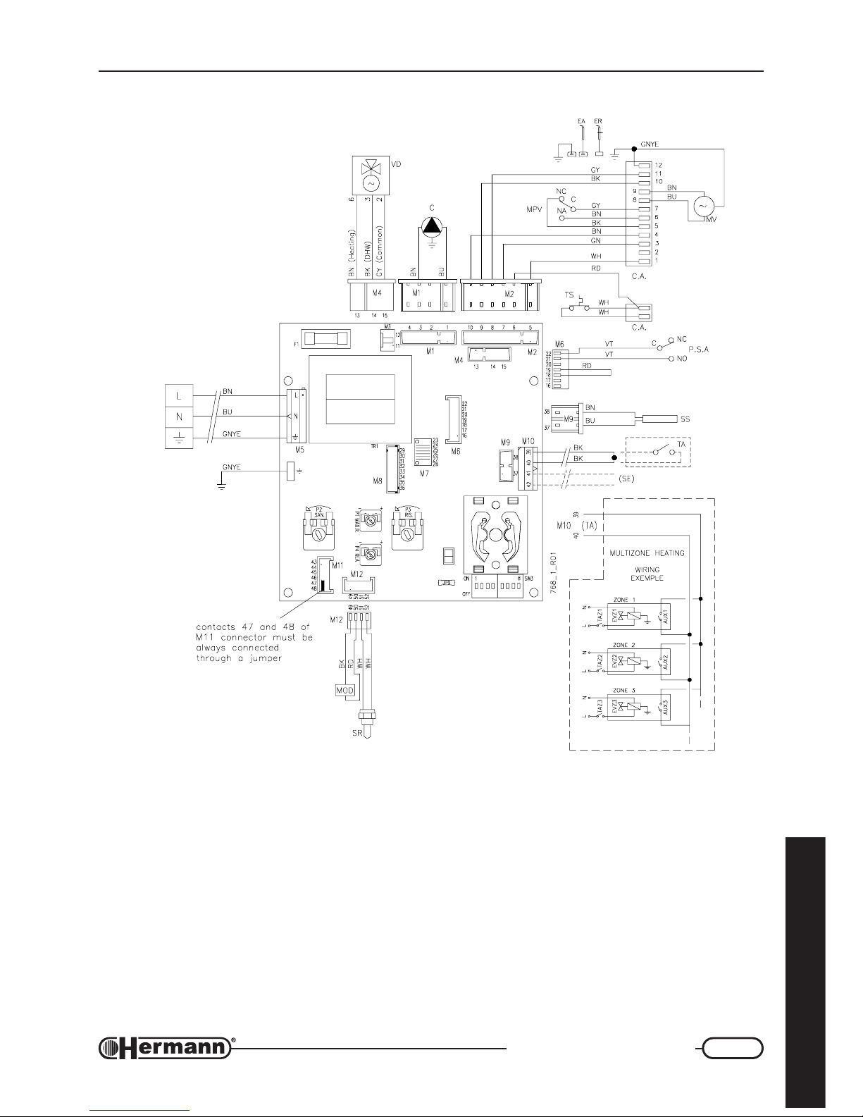
Electric diagram for
SUPERMASTER 24 SE - 30 SE
C Pump
CA Ignition and flame control unit
EA Ignition electrode
ER Flame sense electrode
F1 Fuse (2 A)
MOD Modulatore
MPV Flue pressure switch
MV Fan motor
PSA Low water pressure switch
(contact NA closed = in pressure)
SR Heating NTC sensor
SS DHW storage NTC sensor
TA Voltage-free Contact for Room Thermostat
or Cronothermostat
(for trade) (safety extra low voltage SELV)
TS Safety thermostat
VD Motorized deviating valve
(SE) Arrangement for external
sensor (optional)
EVZ1/2/3… Electrovalve
zone 1/2/3…
AUX1/2/3… Auxiliary contact for
EVZ1/2/3…
TAZ1/2/3… Room thermostat
for zone 1/2/3…
Colours
abbreviations:
BK Black
BN Brown
BU Blue
GN Green
GNYE Green-Yellow
GY Grey
OG Orange
RD Red
VT Violet
WH White
Page 38
38
User instructions
for the user
USER INSTRUCTIONS
Warnings for first starting up
The first starting up must be done by a professionally qualified staff (for example the
SERVICE CENTERS authorized by HERMANN).
Gas conversion from a specific gas (natural gas or LPG) to another gas, can be made also when
the gas boiler is already installed, but only by a qualified technician. The technician will check that:
a) the label technical data of the gas boiler correspond to those of the gas, water and electrical
supply lines;
b) the main burner regulation is compatible with the gas boiler output;
c) the chimney works correctly, expelling the combustion products;
d) the air supply and the combustion products evacuation work correctly, in accordance with the
requirements in force;
e) the conditions for a correct ventilation are guaranteed, also when the gas boiler is located
inside a furniture.
Useful advices
WARNING for “E” models: The boiler is fitted with a safety thermostat for chimney
draught, operating in case of combustion products return in the installation room.
This device must be always in function, because a combustion products return can
cause chronic or acute intoxications with danger of death. If the thermostat must be
replaced, use the original spare part only. In case of repeated interventions of the
device, check that the Flue Products Outlet System is efficient and made according
to the laws in force (see examples in page 15).
WARNING for “SE” models: The boiler is fitted with a safety flue pressure switch. This
device must be always in function. In case of repeated interventions, call a qualified
technician. If the pressure switch must be replaced, use the original spare part only. In
case of repeated interventions of the device, check that the Air Flue Products Inlet/
Outlet System is efficient and made according to the laws in force (see examples in
page 16).
INSTALLATION AND SERVICING
All installation, servicing and gas conversion operations MUST BE CARRIED OUT BY QUALIFIED
TECHNICIANS authorized by Law n. 46 dtd March 5
th
, 1990 and in accordance with UNI-CIG 7129/
01 and 7131/99 requirements and revisions.
Moreover, in accordance with art.11 section 4 of DPR 412/93 and revisions, boiler MAINTENANCE
operations must be made at least once a year and following manufacturer’s specifications and UNI
and CEI rules in force.
Page 39
39
User instructions
for the user
APPLIANCE BOOKLET OR CENTRAL PLANT BOOKLET
All appliances, even those installed before August 1
st
, 1994, must have an appliance booklet (for
outputs less or equal 35 kW) or a central plant booklet (for outputs more than 35 kW). All ordinary
and special servicing operations and combustion checkings must be written on the booklet, together with the name of the person responsible for servicing.
COMBUSTION CHECKING
Combustion checking is made with a control of the boiler efficiency; this checking must be carried
out only by a person with the requirements of the Law 46/90. Boilers that, after the checking, will
have efficiency rates lower than the ones required and not changeable with suitable adjustments,
must be replaced.
BOILER OPERATION AND SERVICING
The user (owner or tenant of the flat where the boiler is installed) or the administrator of the block of
flats (in case of a central heating system) are responsible for the appliance operation and servicing;
they can both transfer the responsibility of the servicing and eventually of the operation to another
person, which must have the requirements indicated by the Law 46/90. Even if the user or the
administrator decide to assume personally this responsibility, ordinary servicing of the warm air
heater and combustion checkings must be carried out by a qualified technician.
Warnings
— In case of prolonged absence of the user, call the authorized servicing centre to empty the
system.
In case of gas smell:
a) do not press electrical switches, use the telephone or other objects that can pro-
voke sparks;
b) open immediately the windows and the doors in order to cleanse the room air;
c) close the gas supply taps;
d) call a qualified technician.
Do not obstruct the ventilation openings of the gas boiler room, in order to avoid
possible dangerous situations as the creation of poisonous or explosive mixtures.
When the boiler is off for a long period see the Paragraph “Inactivity of the Boiler” for
the necessary precautions about the electrical supply, the gas supply and the protection against freezing.
Page 40
40
User instructions
for the user
Boiler controls
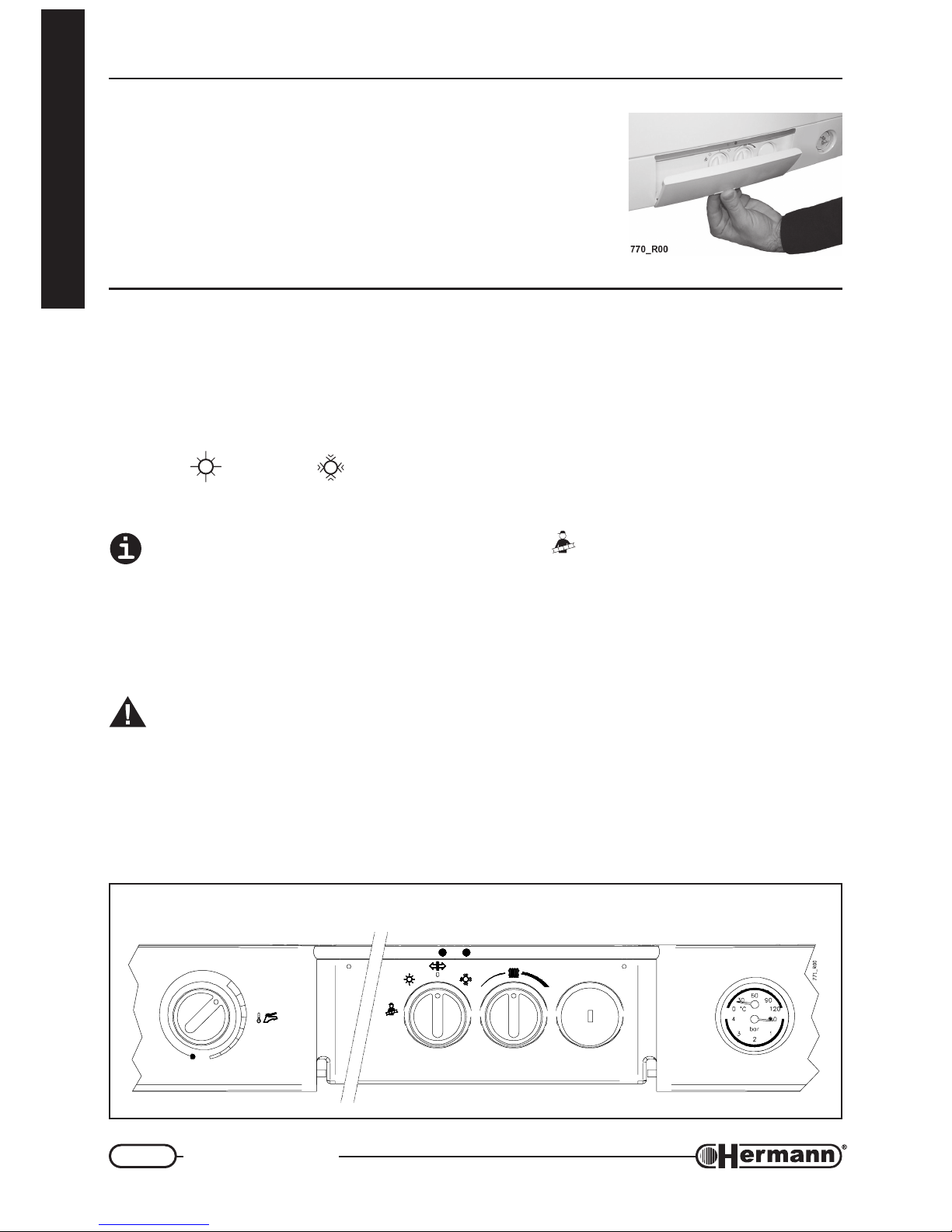
To have the access to the boiler controls it is sufficient to push on
the lower part of the panel, as shown in the figure.
In addition to the controls in the front panel, we remind you that the
boiler must be equipped, during the installation process, with an
external general switch which totally disconnects the boiler from
the electrical supply.
Instructions for boiler ignition,
functioning and turning off
TO START THE BOILER
Open the gas tap and turn on the external general switch. The green lamp [1] flashes to show that
the boiler is supplied but not on (in stand-by). Turn the Selector [2] in the suitable position
SUMMER
or WINTER . The green lamp [1] will turn constantly on to show that the boiler is
on. If the water contained by the boiler is cold or however inferior to the set up temperature, there
will be the ignition of the flame till the heating of the flame.
ATTENTION: Do not activate the Chimneysweeper Function which is reserved for the
installer and which forces the ignition of the burner (the green lamp flashes rapidly). If, by
mistake, it should happen, bring immediately the selector in the central position (0), wait until
the green lamp flashes slowly, and then turn the selector in the desired position.
TO STOP THE BOILER (STAND-BY)
Turn the selector [2] in the central position (0).
If the boiler is off for a long period see the paragraph “INACTIVITY OF THE BOILER”
for the necessary precautions about the electrical supply, gas supply and anti freezing protection.
CONTROL PANEL
1 7
4
C
T
R
O
F
M
O
R
E
P
U
S
2 3
6
5
SUPERBOILER
Page 41

41
User instructions
for the user
SUMMER FUNCTIONING
Turn the selector [2] bringing it in the SUMMER
position
To regulate the temperature of the cold water produced by the boiler, pull and then turn the
knob
[4] for the DHW temperature regulation. The rotation usually requires a certain strenght:
— When the knob is placed inside the SUPERCOMFORT zone (on the right) the hot water outlet
is managed by the boiler in order to ensure the maximum stability of the flow temperature. The
positions on the right offer slightly lower but more stable temperatures and big flows which meet
the needs of several showers or basins of great sizes.
— Turning the knob in anticlockwise sense towards SUPERBOILER (on the left) you can obtain
progressively the maximum available temperature. This regulation is indicated when you need
very hot water.
In case of not ignition of the boiler (and consequently of cold water supply) check that the red lamp
[7] is not on: if it’s on, turn the selector [2] in the central Off/Unlock
Position, wait until the red
lamp [7] turns off, and then bring it again in the SUMMER position. See “Working and warning
indicators” for more information and useful advices to solve common problems.
REMARK: at the interval of 7 days the boiler automatically provides for the heating of the water in
the boiler to more than 60°C, so as to avoid eventual bacters which form in quiet water.
WINTER FUNCTIONING
Turn the selector [2] bringing it in the WINTER
Position.
Regulate the Boiler Thermostat
[3] at the desired temperature.
If a Room thermostat or a Cronothermostat is installed, the regulation of this last keeps the room
temperature as that arranged (refer to the respective using instructions). In this case it is useful to
regulate the boiler thermostat
according to the outdoor seasonal climate, so as to allow the
gaining of the desired temperature, but without excessive overheatings (consider that the radiators
emit heat also after the turning off of the boiler).
The hot water regulation is the same in both winter and summer mode: see previous “SUMMER
FUNCTIONING” for details.
In case of not ignition of the boiler, check that the red lamp [7] is not on: if it’s on, turn the selector [2]
in the central Off/Unlock
Position, wait until the red lamp [7] turns off, and then bring it again in
the WINTER Position. See “Working and warning indicators” for more information and useful
advices to solve common problems.
Important:
The temperature in the boiler is shown by the thermometer [5] and the pressure is shown by the
Gauge [6].
Remark: If pressure falls down to 0.5 bar, boiler will stop (the red lamp turns on). To reset the
system, proceed with system filling.
Page 42
42
User instructions
for the user
ROOM TEMPERATURE REGULATION
We want here to remind you that the room tem-
perature must be regulated through a room thermostat with two temperature levels. This required
by DPR 26 Agosto 1993 n°412 and relevant
changes.
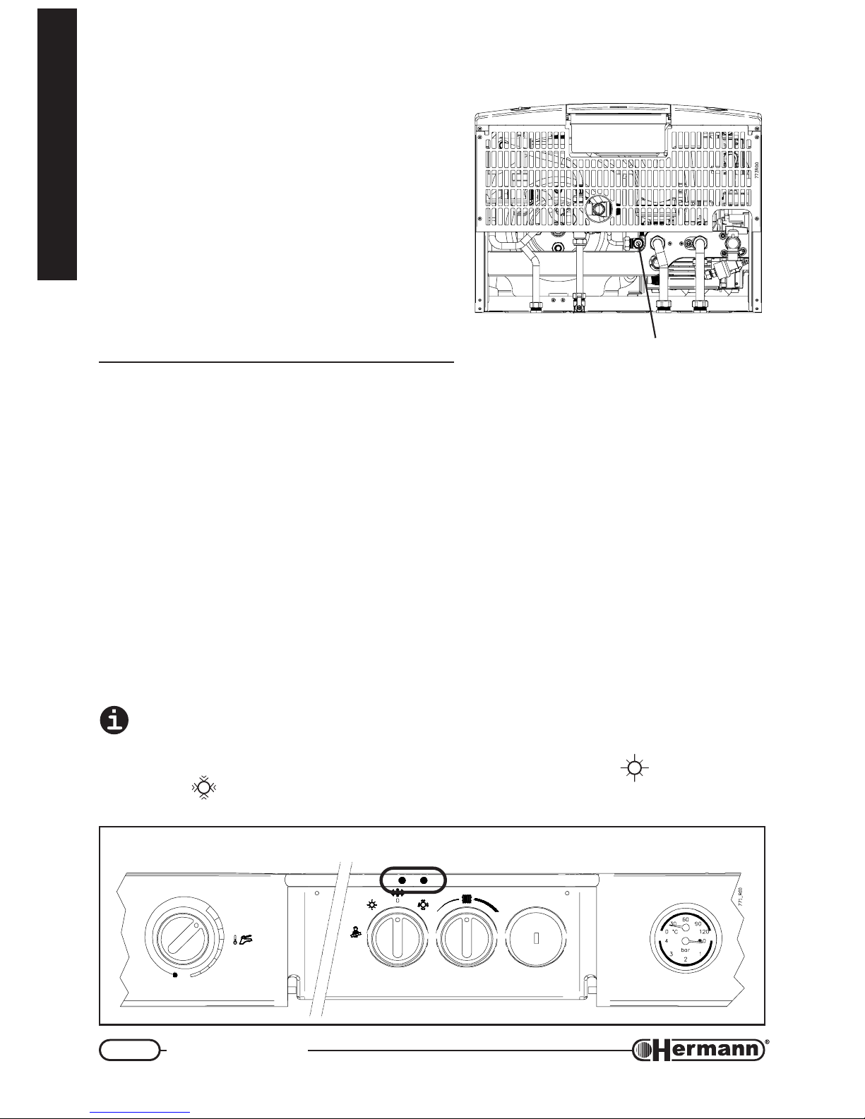
SYSTEM FILLING
Make sure that the system pressure in a cold state is
always between 0.5÷1.5 bar (optimal pressure: 1÷1.5
bar). If pressure is lower, open the filling valve (see
figure) till it reaches a maximum value of 1,5 bar; this
value is checked with the pressure gauge (item 6 in
previous Control Panel figure).
Working and warning
indicators
GREEN FUNCTIONING LAMP [1]
The green lamp can be off, flashing (slowly or rapidly) or on.
OFF: the boiler is electrically disconnected. In these conditions the boiler obviously doesn’t
work. The Automatic Anti Freezing and Anti Blocking functions can’t be activated (useful during
long period of inactivity). The external general switch could be off.
FLASHING (slowly): the boiler is electrically supplied but the SUMMER/WINTER Selector is in
central position (0). The boiler will not turn on following the needs of heating and water in the
boiler won’t be maintained hot, but the Anti Freezing and Anti Blocking Functions are on (this
last can request the temporary ignition of the burner, then it is necessary that the gas is open).
FLASHING (rapidly): the Chimneysweeper Function (which is reserved for the technician) is on
by mistake.
Turn it off bringing the SUMMER/WINTER selector in the central position (0) until the green
lamp flashes slowly.
ON: the boiler is on and the SUMMER/WINTER selector is in the SUMMER
Position or in the
WINTER Position. The boiler will turn on following the needs of heating or to keep the water
in the boiler hot.
BOILER BOTTOM VIEW
HEATING SYSTEM
FILLING TAP
CONTROL PANEL
1 7
4
C
T
R
O
F
M
O
R
E
P
U
S
2 3
6
5
SUPERBOILER
Page 43

43
User instructions
for the user
BOILER’S LOCK OUT RED LAMP [7]
The red lamp can be off, flashing and on.
OFF: the functioning of the boiler is correct.
FLASHING:
— One of the internal sensors of the boiler has been damaged. Call a Qualified Techni-
cian for repairing.
ON - it signals problems that can be normally solved by the user:
— The boiler has been just installed, or works have been made on the gas pipes.
It is normal that the boiler goes repeatedly in Lock Out when the Inlet Gas is mixed
with air. This impedes the correct ignition and then provokes the Lock out. In the
conditions described above, it is necessary to repeat more times the ignition of the
boiler turning the SUMMER/WINTER Selector in the Unlock
Position until the
red lamp turns off.
— The water pressure, shown by the gauge in the control panel, is not sufficient (0,5 bar
or lower).
Restore the correct pressure (optimal pressure: 1÷1,5 bar at cold system) opening
the inlet tap (the action is described before). Do not restore the pressure with hot
system, because when the system gets cold the pressure decreases.
Consider that the pressure, in normal conditions, should not decrease.
If this happens, there is probably a loss in the heating system. Sometimes the loss is so small
that it doesn’t leave evident signs, but with the progress of the time it can cause the
decreasing of the pressure.
Also the opening of the Manual Radiator Outlet taps (intentional or unintentional)
makes the pressure decrease. Check that this doesn’t happen.
— the boiler has an overheating and the Safety Thermostat has triggered;
Turn the SUMMER/WINTER Selector in the central Unlock
Position until the
red lamp turns off (or eventually for a longer period to make the boiler cool), then
bring again the selector in the desired position (Summer or Winter ). If the
Lock Out takes place again call the Service Centre.
— the burner hasn’t regularly switched on or the flame has suddenly turned off; incor-
rect combustion.
Restore the service turning the SUMMER/WINTER selector in the Unlock
Position
until the red lamp turns off. In case of frequent Locks:
• Call a technician to check the combustion and verify that the burner is clean and in
good conditions;
In “SE” models with Sealed Combustion Chamber:
• Check that the Inlet/Outlet Ducts and the respective terminals are clean and in good
condition, and that there are no leaks. During the Installation Process it is necessary
Page 44

44
User instructions
for the user
to respect the prescriptions included in the national and local regulations and laws, in
addition to the slopes and measurement included in the paragraphs “Chimney connections” and “Flue systems”.
Note for the TECHNICIAN: The burner flame is not detected by the Flame Control Unit becouse it has not
turned on or it has suddendly turned off, or it has detached from the burner, because of an incorrect
combustion. This can be due, in exemple, to combustion product reflowing into inlet duct, leaks in inlet/
outlet ducts or errors in sizing of ducts (ducts length above or below the allowed, and/or wrong use of
restrictor on boiler’s outlet).
— “E” models with Natural Draught only: the device which signals the wrong Flue
Outlet has intervened;
Exceptionally the cause can be a strong wind gust.
Restore the service turning the SUMMER/WINTER selector in the Unlock Position until the red lamp turns off. In case of
frequent Locks:
• Check the efficiency of the Flue.
• Check that the outlet which communicates with the outdoor, compulsory according
to the law, is not obstructed by pieces of furniture against the wall or by other objects.
It is however normal that the outlet is realized behind a radiator.
The outlet must be of
the dimension prescribed by the law and must be cleaned inside: some types have
an anti-insects net which could have been dirtied by dust or by spider’s webs. Call a
Qualified Technician when it is necessary.
• If in the room where the boiler is installed there are mantelpieces, stoves, coal stoves
or similar, fans for the Air Outlet, such as wall fans, aspiring cowls for cooking boards
with outlet pipe, let the technician check that the inlet is correctly OVERSIZED or that
there are the ADDITIONAL Inlets as prescribed by the laws in force, because, otherwise, these devices interfere with the evacuation of the Boiler’s Flue.
Boiler inactivity
The effects of the periods of inactivity can be relevant in particular situations such as in flats used
only for some months per year, most of all in cold places.
The user will have to decide to put the boiler in the SAFETY LOCK OUT state disconnecting all the
supplies, or to leave it in stand-by and use the Anti Freezing Function. In general it is better to
use the SAFETY LOCK OUT. When there is the possibility of freezing it is convenient to chose
between the advantages and the disadvantages of the SAFETY LOCK OUT and of the Stand By/
Anti Freezing Way.
SAFETY LOCK OUT
— Turn off the general switch on the Electrical Supply Line of the Boiler;
— Close the Gas Tap;
When it is expected that the temperature is going to decrease under 0°C and the system
doesn’t include the Anti Freezing Function, empty the heating system totally, or fill it with an
Anti Freezing Solution, and empty the tank.
Notice that if it had been necessary to restore the pressure (because of possible loss) in an
heating system already filled with an Anti freezing solution, the concentration of the system
could have decreased and it could not guarantee the Anti freezing Protection.
Page 45

45
User instructions
for the user
REMARK: the boiler is equipped with a system which protects the main components from the
exceptional cases of LOCK OUT, due to the inactivity in presence of water and scale. The Anti
Lock out System can’t work during the Safety Lock Out Process, because of the lack of electrical supply.
STAND-BY AND ANTI FREEZING/ANTI LOCK OUT FUNCTION
The boiler is equipped with an Anti freezing System which provides the ignition of the boiler whenever the temperature of the water - in the heating circuit or in the tank inside the boiler - decreases
under 5°C and which provides the turning off when the temperature reaches 30°C. In order to
activate the Anti Freezing Function:
• electrical power supply MUST be ON;
• boiler must be left in stand-by mode (Summer/Winter selector on 0, green lamp flashing);
• the gas must be left open;
• system pressure must be correct (1÷1.5 bar in a cold state, minimum 0.5 bar).
In case of lack of gas, the burner won’t turn on and the boiler will go in LOCK OUT state (red lamp
on or flashing). Nevertheless the pump will work, making the water circulate in the system and
reducing in this way the possibility of freezing.
Moreover, the boiler in stand-by activates periodically the main internal components to prevent the
exceptional cases of Lock out due to the inactivity in presence of water and scale. This happens
also if the boiler goes in Lock Out state (red lamp on or flashing).
“ROOM ANTIFREEZING” FUNCTION
If the flat (where the boiler is installed) remains unused for a period with cold temperature, you can
consider the possibility to extend the antifreezing capability of the boiler, to all the heating system
(and to the flat rooms). Also in this case, are needed the presence of all supplies (electric, gas) and
the correct system pressure.
— if the REMOTE CONTROL (original optional kit) is installed the antifreeze function is auto-
matically started by putting the boiler in Stand-by by means of the relevant pushbutton on the
Remote Control. The boiler, the rooms and the DHW tank will be kept at a minimum temperature as to avoid the freezing of the liquids in them;
— if a common thermostat or chronothermostat is installed, featuring* an “anti freezing” func-
tion and you want to use it, it’s necessary to set the boiler in Winter
mode and NOT in
Stand-by, to allow it to heat the heating circuit when the room temperature sensor requires it. To
avoid extra gas consumption, it’s advisable to ask a technician to set the tank temperature to
the minimum, as described in “Hydraulic section” paragraph, “Regulation” section, back in this
handbook (otherwise boiler will heat the water in the tank, without any reason).
* if it’s without this specific function, it’s possible anyway to set the room temperature to a few degrees above the
freezing temperature, in exemple +5°C (if you have a chronothermostat, remember to choose the manual
mode).
Page 46

46
User instructions
for the user
Incidental not functioning
THE BURNER DOESN’T TURN ON
— If the room thermostat is installed, check that this is regulated with an higher temperature in
respect of that of the place where it is installed;
— check that there is electrical supply and that the Summer/Winter Selector isn’t on 0 (stand-by)
but on SUMMER
or WINTER . The GREEN lamp must be constantly ON (see details in
the paragraph “Working and warning indicators”);
— if the Lock Out red lamp is on or flashing, see the paragraph “Working and warning indicators”;
— check on the gauge that the boiler pressure is correct (1÷1.5 bar in a cold state) or at least not
lower than 0.5 bar.
— In SE Models, in some cases, eventual problems with the flue outlet impede the ignition of the
boiler without turning on the unblock red indicator. You have to check the ducts for the inlet and
the outlet, the relevant terminals and the device which controls the correct flue outlet. In the
installation process the prescriptions connected to the laws and the national and local rules
must be respected together with the rules contained in the paragraph “Chimney connections”.
SHORTAGE OF DOMESTIC HOT WATER PRODUCTION
— make sure that D.H.W. thermostat
is not set on a too low position;
— call a qualified technician to check gas valve regulation;
— let a technician check the storage temperature regulation, in the case it has been set to the
minimum because of an inactivity period, using the “room antifreeze” procedure (see “Boiler
inactivity” and “Hydraulic section”);
— call a qualified technician to check, and eventually clean, the hot water tank.
Remark: where the water hardness value is too high, it is suggested the installation of a
softening device, in order to prevent the limestone precipitation; this operation avoids a frequent cleaning of the coil.
Do not try to repair the gas boiler by yourself.
For any intervention on the electrical, hydraulic or gas circuit exclusively call a qualified
technician.
The gas boilers must be fitted with original accessories only.
HERMANN Ltd. is not responsible for damages caused by the incorrect, wrong or unreason-
able use of non-original materials.
Page 47

User warnings
— Check frequently water pressure on the hydrometer and verify that, when the system is cold,
water pressure values are in line with the manufacturer instructions.
— If water pressure is frequently dropping down, call a qualified technician to repair possible
leakages in the system.
— If the boiler is off for a very long period, see the Paragraph “Inactivity of the Boiler” for the
necessary precautions about the electrical supply, the gas supply and the protection against
freezing.
— Every 6 months make the check of the efficiency of the magnesium anode which protects the
water heater from the corrosion, and if necessary, replace it.
Do not touch the heated surfaces of the boiler, as the doors, the flue, the chimney
pipe, etc., also after the boiler operation because, for a certain time, these surfaces
are oveheated. Any contact with them can cause dangerous scalds. It is then forbidden to let children or inexperienced people be close to the boiler, during its operation.
— Do not expose the wall hung gas boiler to water vapours directly coming from gas cookers/
hobs.
— Do not wet the gas boiler with water or other liquids sprinklings.
— Do not put any object on the gas boiler.
— The gas boiler utilization is forbidden to children and to inexperienced people.
— If the gas boiler is going to be definitively unused, call a qualified technician to carry out all
required operations, checking in particular disconnection of gas, water and electrical supplies.
— Only on
SUPERMASTER E models (natural draught): the installation of aspirators, fire-
places or similar appliances in the boiler room (and in adjacent rooms in case of indirect ventilation), must be made in compliance with all specific safety rules and laws (for example by
augmenting the dimensions of ventilation openings), even in case of modifications or additions.
INSTRUCTIONS MANUAL
Make sure that the present manual is ALWAYS with the boiler, for any consultation of the user and
servicing personnel.
HERMANN CONVENTIONAL GUARANTEE CONDITIONS
Hermann offers to the customer a particular and exclusive CONVENTIONAL GUARANTEE, which
is automatically activated asking the First Ignition to a Hermann Authorized Service Center. The
conditions of the HERMANN CONVENTIONAL GUARANTEE don’t prejudge nor invalidate the
rights indicated by the European Rule 1999/44/CE actuated with Italian Laws by the Decree 02
Februar 2002 N°24 of which the User is the Owner.
Page 48

07/2003 COD. 982160038 / REV. 003
(UKENG)
HERMANN S.r.l. Via Salvo d’Acquisto 29010 Pontenure (PC)
Tel. 0523/510341 Fax 0523/510359
E-MAIL : [email protected]
http://www.hermann.it
La Hermann s.r.l. declina ogni responsabilità per eventuali errori di stampa e/o di trascrizione contenuti nel presente libretto.
Nell’intento di migliorare costantemente i propri prodotti, la Hermann s.r.l. si riserva il diritto di variare le caratteristiche ed i dati indicati nel presente libretto in qualunque momento e senza preavviso,
il presente pertanto non può essere considerato come un contratto nei confronti di terzi.
 Loading...