

Page 1

EURA
23 E – 28 E
23 SE – 28 SE – 32 SE
Quick guide
Technical Data
Installation, adjusting
and maintenance instructions
User instructions
GAS BOILERS
Page 2
Warnings
WARNING
MANUFACTURER DECLARATION
Hermann boilers have obtained the CE certification (DM dtd. April 2nd 1998, Law 10/91, art. 32) and
meet minimum efficiency requirements, both at normal and 30% load, provided by DPR 412/93
(according to Law 10/91, art. 4, sub-section 4). They are in conformity with following Directives: Directive
on appliances burning gaseous fuels (90/396), Directive on electro-magnetic compatibility (CE 89/
336), Efficiency Directive (CE 92/42), Low Voltage Directive (CE 73/23), and relevant modifications.
ATTENTION
(for EURA 23/28/32 SE)
FOR DIAPHRAGM POSITIONING, CAREFULLY READ THE FLUE SYSTEMS
INSTRUCTIONS IN THE “INSTALLATION” CHAPTER.
IMPORTANT
THE FIRST IGNITION OF THE BOILER MUST BE EXECUTED BY AN
AUTHORIZED TECHNICIAN ACCORDING TO THE LAW 46/90.
for the technician and for the user
Assigning all the operations for the first ignition to a Hermann Authorized Service
Center the particular and exclusive Hermann Conventional Warranty is activated.
For further information consult the coupon which you can find in the boiler’s
documents envelope.
Assigning all the operations for the first ignition to a Hermann Authorized Service Center the particular and exclusive Hermann Conventional Warranty is activated. For further information consult the coupon which you can find in the boiler’s documents envelope.
DANGER: All warnings preceded by this symbol MUST be carefully respected so as
to avoid any accident of mechanical (e.g. wounds or contusions) or general origin.
DANGER: All warnings preceded by this symbol MUST be carefully respected so as
to avoid any accident of ELECTRICAL origin (fulguration).
DANGER: All warnings preceded by this symbol MUST be carefully respected so as
to avoid any accident of THERMIC origin (scalds).
Attention: All warnings preceded by this symbol MUST be carefully respected so as to avoid
any disfunctioning and/or damage to the appliance or other objects.
2
Page 3

Warnings
The instructions manual is an essential and complementary part of the product and it is
supplied together with the boiler.
Carefully read the manual, achieving all important information for a safe installation,
use and servicing.
— Carefully keep the manual for any further consultation you may need.
— The installation must be carried out by a qualified technician, in accordance with
manufacturer instructions and with the relevant requirements of the current issue.
— A qualified technician is a person with a specific technical competence in the field of the
heating appliances for domestic use and domestic hot water production, as indicated
by the Law [ID of Your National rule, if any, regarding Technicians competence].
— Operation that User can perform are limited to those described in “USER INSTRUCTIONS”
section.
— The manufacturer has no contractual and extra-contractual responsibility for any damage
arising from wrong installation, wrong use and non-observance of current laws and
instructions given by the manufacturer himself.
— Important: this gas boiler is used to heat the water at a temperature lower than the boiling one,
at atmospheric pressure; it must be connected to an heating system and/or to a domestic hot
water system, in accordance with its features and power.
— Packing items (cartons, nails, plastic bags and so on) must not be left within children
easy reach, as they are potentially dangerous.
— Before any cleaning or servicing operation, switch off the main electrical switch of the
heating system and/or any other suitable switch providing electrical disconnection of
the gas boiler.
— In case of fault and/or bad operation of the appliance, disconnect it immediately and do
not try to repair it by yourselves.
Boiler servicing and repair must be carried out exclusively by [HERMANN Authorized Servicing
Centres] [qualified technicians], which will use original spare parts. Strictly observe the above
requirement, avoiding any risk of compromising the appliance safety.
— If the appliance should be definitively disconnected, remove or cut off any potential dangerous
item.
— When selling the appliance or leaving it installed after a removal, make always sure that the
instructions manual is close to the boiler for the future use of new owners and/or installers.
— This appliance must be used for its clearly recommended utilization only. Any other utilization
must be considered dangerous and incorrect.
— It is strictly forbidden to use the appliance for different purposes than the specified ones.
for the technician and for the user
— This appliance must be installed exclusively to wall.
3
Page 4

Index
INDEX
Warning .........................................2
Technical data...............................5
Installation ....................................8
Safety laws and rules referred to
technicians assigned to boilers
installation ....................................... 8
Reference norms and laws
for installation .................................. 8
Boiler location ....................................... 9
Fixing the boiler .................................. 10
sections for the usersections for the technician
Dima di fissaggio ................................ 10
Hydraulic connections ........................ 11
System filling ...................................... 12
Gas connection .................................. 13
Electrical connections ......................... 13
Chimney connections
EURA E (natural draught) .............. 15
Chimney connections
EURA SE (forced draught) ............ 16
High capacity fan
EURA 23 SE.................................. 18
Flue options
EURA SE ...................................... 19
First firing,
regulation and
servicing instructions ................21
Gaining access to
manual regulation devices ............. 21
Preliminary gas control ....................... 21
MAX-MIN pressure adjustment
on GAS valve ................................ 22
Regulation programming .................... 23
Slow opening regulation ..................... 25
Max heating power
regulation....................................... 25
Gas transformation ............................. 28
Combustion check .............................. 29
Excluding automatic by-pass .............. 29
Draining EURA boiler ......................... 30
Other boiler programme...................... 31
Crypt Warnings for Technical experts . 33
Servicing warnings ............................. 35
Boiler internal components ................. 36
Electrical diagram ......................39
User instructions ........................41
Warnings for boiler
commissioning............................... 41
Useful tips........................................... 41
Warnings ............................................ 42
Gaining access to control panel.......... 43
Switching on/off
and running boiler .......................... 43
Control panel details ........................... 45
Boiler blocking and alarm codes ......... 47
Eventual problems .............................. 50
Warning while using ........................... 51
4
Page 5
Technical data
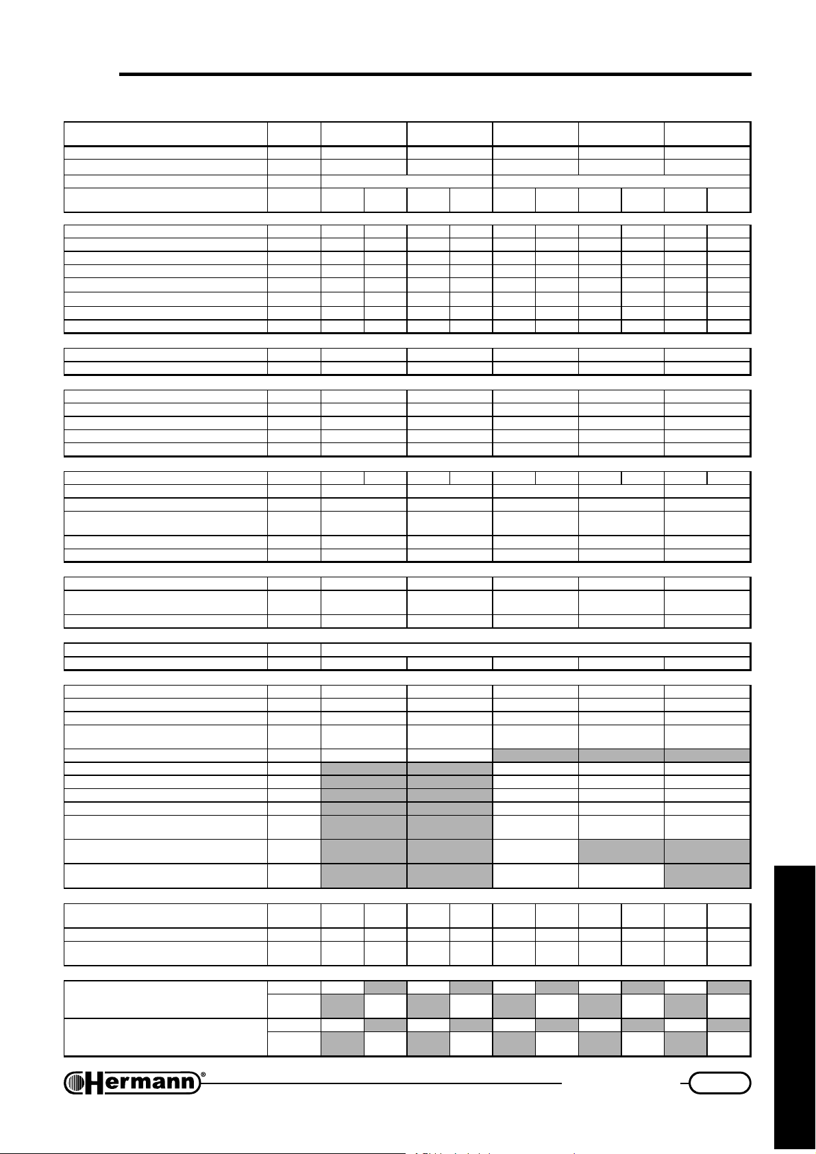
TECHNICAL DATA
ATADLACINHCET.M.UE32ARUEE82ARUEES32ARUEES82ARUEES23ARUE
noitacifitrecEC°n9892LB49609892LB49609892LB49609892LB49609892LB4960
ssalC
epyT SB/11B 28C-26C-25C-24C-23C-21C-22B
epytsaG02G
II
+3H2
/03G
13G
II
+3H2
02G
/03G
13G
II
+3H2
02G
/03G
13G
II
+3H2
02G
/03G
13G
II
+3H2
02G
/03G
13G
)iH(tupnitaehxaMWk6.526.520.130.136.526.520.130.135.43
)iH(tupnitaehniMWk5.015.012.312.315.015.012.312.315.31
)iH(tuptuotaehxaMWk1.321.320.820.827.327.325.825.827.13
ON
ssalC
x
OC
2
GNITAEH
htdiW htpeD-thgieH- mm
thgieW
htiw nafyticapachgih
epytsaG
xamQ
nimQ
)iH(tuptuotaehniMWk30.930.94.114.1170.970.92.112.114.11
ONdethgieW
x
tupnilanimontaOCmpp0.040.070.530.260.63
tupnilanimonta
YCNEICIFFE
ycneiciffelanimoN%8.097.092.393.298.19
daol%03taycneiciffE%1.880.984.090.099.88
lessevnoisnapxE l88888
erusserplessevnoisnapxErab11111
erusserpgnikrowxaMrab33333
erutarepmetmetsysxaMC°5858585858
RETAWTOH
wolfretawniMnim/l5.25.25.25.25.2
erusserpylppusxaMrab66666
)hctiwsytiroirp
ATADLACIRTCELE
ycneuqerf/egatloVzH/V05/03205/03205/03205/03205/032
noitpmusnocrewoP
noitcetorpfoleveLD4XPID4XPID4XPID4XPID4XPI
SNOISNEMID
)teltuO=S(SNOITCENNOC
nruter/wolfgnitaeHcnI"¾"¾"¾"¾"¾
teltuo/telniretaWcitsemoDcnI"½"½"½"½"½
reliobehtotnoitcennocsaGcnI"¾"¾"¾"¾"¾
tiknoitcennocdradnatsfo
ØteltuostcudorpeulFmm031041
xam/nimhtgneleulfetarapeSm
xam/nimhtgneleulfetarapeS
xam/nimhtgneleulfetarapeS
rettilpsepiphtiw
ERUSSERPYLPPUSSAG
erusserplanimoNrabm0273/920273/920273/920273/920273/92
retemaidsrotcejnI
NOITPMUSNOCSAG
)xam÷nim(egnarnoitceleserutarepmeT
esirerutarepmetC°03taetarwolFnim/l0.110.113.313.313.11
ehtfonoitavitcaehtrof(erusserpylppusniM
)xam÷nim(egnarnoitceleserutarepmeT
)retawtoh/gnitaeh(yticapacknatiniMl9.0/2.39.0/2.39.0/2.39.0/2.39.0/2.3
)nafyticapachgihhtiw=PAV(
kcocsagehtotnoitcennocsaG
Øtelniria/teltuostcudorpeulflaixaoCmm 06/00106/00106/001
xam/nim)latnoziroh(htgneleulflaixaoCm
xam/nim)lacitrev(htgneleulflaixaoCm
Øtelniria/teltuostcudorpeulfetarapeSmm
31313
hWk/gm321532141802731
%8.48.51.50.67.6
C°08÷0308÷0308÷0308÷0308÷03
rab4.04.04.04.04.0
C°55÷0355÷0355÷0355÷0355÷03
W001031)PAV061(051071581
gk5.1424648494
cnI"½"½"½"½"½
m
m
Ø
mm001/1
h/cm17.2
h/gk
h/cm11.1
h/gk
02G
02157/5702157/5702157/5702157/5703177/77
/03G
13G
89.1
18.0
02G
82.3 17.2 82.3 56.3
/20.2
04.1 11.1 04.1 34.1
/38.0
/03G
13G
/44.2
04.2
/40.1
20.1
2
4÷5,03÷5,03÷5,0
5÷14÷14÷1
080808
03÷2
06÷13
41÷2
02G
323
851
0.84
0.8
3.11
)02=Sxam(
)04=Sxam(
)31=Sxam(
13G
89.1
18.0
margaid"SNOISNEMID"otrefeR
/03G
/20.2
/38.0
531161421
0.520.820.84
8.64.73.6
6.316.311.51
52÷2
01÷2
02G
)02=Sxam(
)7=Sxam(
/03G
13G
04.2
20.1
02G
/44.2
/40.1
1.43
5.31
3.13
4.11
2
681
0.93
2.7
0.51
02÷2
)21=Sxam(
for the technician
/03G
13G
/86.2
46.2
/60.1
50.1
5
Page 6
Technical data
EURA
L P
E - SE
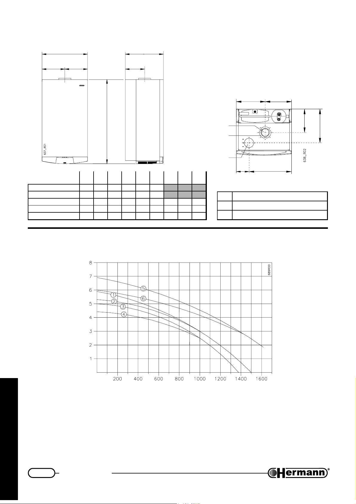
DIMENSIONS
YX
Q
H
L
H
P
X
Y
Q
R
ledomrelioB
E32ARUE054338773702342522
E82ARUE054338773232812522
ES32ARUE05433877370234219167257573
ES82ARUE054338773752391191672421623
ES23ARUE054338773752391191672421623
)mm(
)mm(
)mm(
)mm(
)mm(
)mm(
S
)mm(
EURA 23-28-32 SE
models only:
X Y
Q
1
R
2
3
S T
T
)mm(
)mm(
1teltuostcudorpeulF
2metsyslaixaocroftelniriA
3metsysetarapesroftelniriA
EURA - AVAILABLE PUMP CAPACITY
O
2
Pressure m. H
for the technician
1–EURA 28 available pump capacity (closed By-pass)
2–EURA 28 available pump capacity (automatic By-pass)
3–EURA 23 available pump capacity (closed By-pass)
4–EURA 23 available pump capacity (automatic By-pass)
5–EURA 32 available pump capacity (closed By-pass)
6–EURA 32 available pump capacity (automatic By-pass)
Water flow l/h
6
Page 7
Technical data
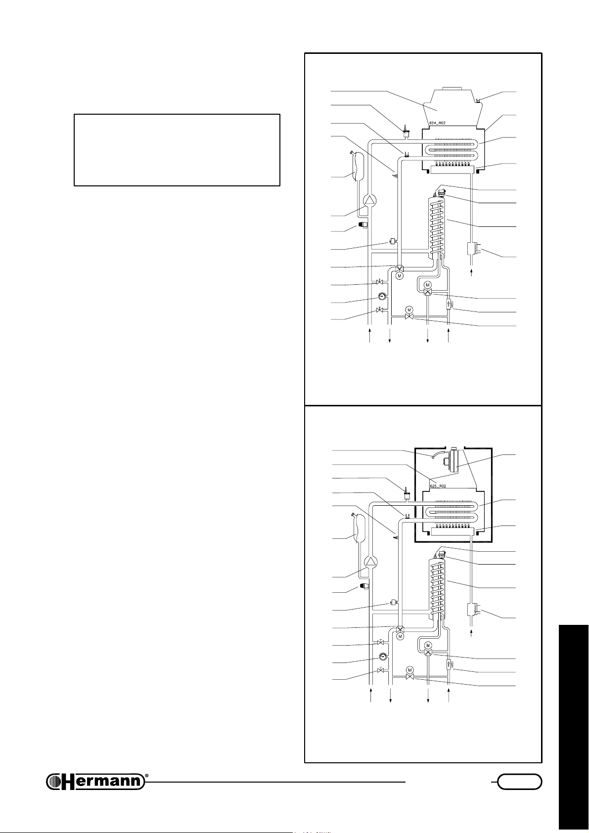
BOILER SCHEMATIC
EURA E
WARNING: This scheme is made for information only. To make boiler hydraulic connection either use fixing jig or the
drawing inserted in the section “Installation”.
1 Drain valve
2 Manometer
3 By-pass
4 Three way motorised valve
5 Loss of water switch
6 Heating system safety valve 3 bar
7 Pump
8 Expansion vessel
9 Flow temperature sensor
10 High temperature safety switch
12
11
10
9
8
7
6
5
4
3
2
1
FLOW
RETURN
HEATING
EURA SE
OUTLET
DOMESTIC
WATER
13
14
15
16
17
18
19
20
GAS
21
22
23
INLET
11 Automatic air vent
12 Flue hood (“E” and “SE” models)
13 Flue thermostat (“E” models)
Flue pressure switch (“SE” models)
14 Combustion chamber (“E” models)
Fan (“SE” models)
15 Primary heat exchanger
16 Burner
17 Domestic minitank temperature sensor
18 Domestic minitank automatic air vent
19 Domestic heat exchanger
20 Gas valve
21 Motorised mixing valve
22 Priority flowstat
23 Electric filling valve
13
12
11
10
9
8
7
6
5
4
3
2
1
RETURN
HEATING
FLOW
OUTLET
DOMESTIC
WATER
INLET
GAS
14
15
16
17
18
19
20
21
22
23
for the technician
7
Page 8
Installation instructions
INSTALLATION
Safety laws and rules referred to technicians
assigned to boilers installation
Place here all necessary
advices according to national rules
about WORK SAFETY
Exemple:
Law number XXXX
“Actuation of 89/391/CEE; 89/655/CEE, 90/296/CEE, 90/934/CEE, 90/679/CEE, (work safety)”
Law number XXXX
“Actuation of 89/686/CEE (21 Dec 1989)”
Other Law number XXXX (if any)
“Other Law title and/or brief description”
Directives
“Directive title and/or brief description”
Always proceed with caution when handling the boiler and carrying out
installation/maintenance work as metal parts may cause injuries such as cuts
and abrasions. Wear gloves while doing the above mentioned operations.
Reference norms and laws
for installation
Place here all necessary
advices according to national rules
about BOILER INSTALLATION
Exemple:
Law number XXXX
for the technician
“Law title and/or brief description”
8
Page 9
Installation instructions
Boiler location
INSTALLATION ROOM
When having an heat ouput lower than 35 kw (about 30000 Kcal/h), particular features for the
installation room are not required. Shortly, all installation rules assuring a safe and regular gas
boiler operation, must be strictly respected.
Place here all necessary
advices according to national rules about:
- Installation room requirements
- Limitations in power and/or number of boilers and other
appliances in the same room
Exemple:
Law number XXXX
“Law title and/or brief description”
INSTALLATION IN ROOMS WHERE TEMPERATURE CAN DROP DOWN TO 0°C:
When the installation place does not guarantee an adequate repair against atmospheric agents,
the gas boiler must be completely protected through an adequate coverage as a safety measure
against the above agents.
In case of boiler installation in rooms where temperature can drop down to 0°, it is advisable to
protect the heating circuit with an antifreeze liquid. See the “System Filling” section.
This appliance is not suitable for outdoor installation.
ROOM VENTILATION (
When a natural draught boiler is installed, permanent ventilation of the installation
room is mandatory and extremely important. Ventilation must be made and sized in
accordance with Laws and Rules in force.
EURA E - natural draught)
for the technician
9
Page 10
Installation instructions
Fixing the boiler
For the installation proceed as follows:
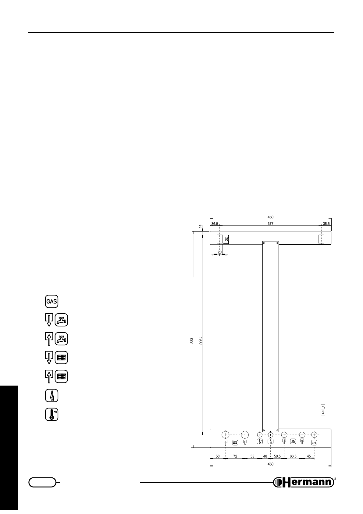
Appliance size and clearances for maintenance: 50mm from both sides and 300mm from the
bottom are reccommended.
— Attach template to the wall (see figure below) with two brackets suitable to carry boiler weight;
— fix up electrical connections and all ducts for heating flow and return, cold water, hot water and
gas, as indicated on template;
— remove template and hang boiler;
Remark: The template is only used as a guide to align the pipework.
— remove plastic caps and their relevant gaskets from boiler connections. Remove bottom
plastic supports by unscrewing their relevant screws. Keep these screws since you will need
them to install bottom grid;
Remark: We suggest not to fix grid until the boiler is definitively commissioned.
— Connect boiler to the pipework installing a cold
water inlet cock. We also suggest to install
cocks on heating flow and return.
Boiler template
Gas (1/2")
Hot water OUTLET (1/2")
Cold water INLET (1/2")
Heating FLOW (3/4")
for the technician
Heating RETURN (3/4")
Electrical power supply
Room thermostat
10
Page 11
Installation instructions
Hydraulic connections
Remark: If gas cock position is foreseen near the
WALL, install first gas cock, then water inlet
tap.
Advices and suggestions to avoid vibrations and
noises in the system
— Do not use pipes with reduced diameters;
— Do not use bends with small radius and
reductions of important sections;
It is recommended an hot washing of the
—
system
radiators from impurities (in particular oils and
fats) that
DOMESTIC WATER SUPPLY
The pressure of entrance cold water inlet pressure must be lower than 6 bar. Furthermore, for an
optimal boiler functioning, water pressure should be more than 1 bar. A lower pressure could make
difficult to restore correctly the pressure in the heating system, and reduce the flow od hot water
available from the boiler.
in order to purge the pipes and the
could damage the pump.
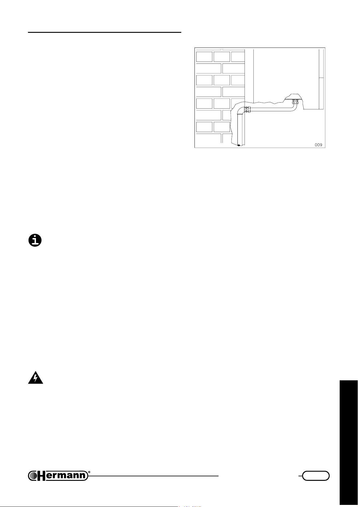
CONNECTION EXAMPLE
If pressure is higher, a PRESSURE REDUCER must be fitted upstream the boiler.
The cleaning frequency of the coil exchanger depends on the water supply hardness. Besides, the
presence of solid residuals or impurities in the water (for example in case of new systems) could
compromise the correct functioning of the boiler.
So, may be necessary to install suitable water treatment device, depending on the water features.
HEATING SYSTEM
— Considering that during boiler operation, the water inside the heating system increases its
pressure, make sure that its maximum value does not exceed the maximum hydraulic pressure
indicated on the appliance data plate.
— Connect the safety evacuation ducts of the boiler to an evacuation funnel. If safety valves are
not connected to an evacuation device, their intervention could flood the room. Hermann cannot
be held responsible for any damage arising from that situation.
Make sure that the hydraulic and heating systems ducts are not used as earth
connections of the electrical system. They are absolutely NOT SUITABLE for such a
use.
for the technician
11
Page 12
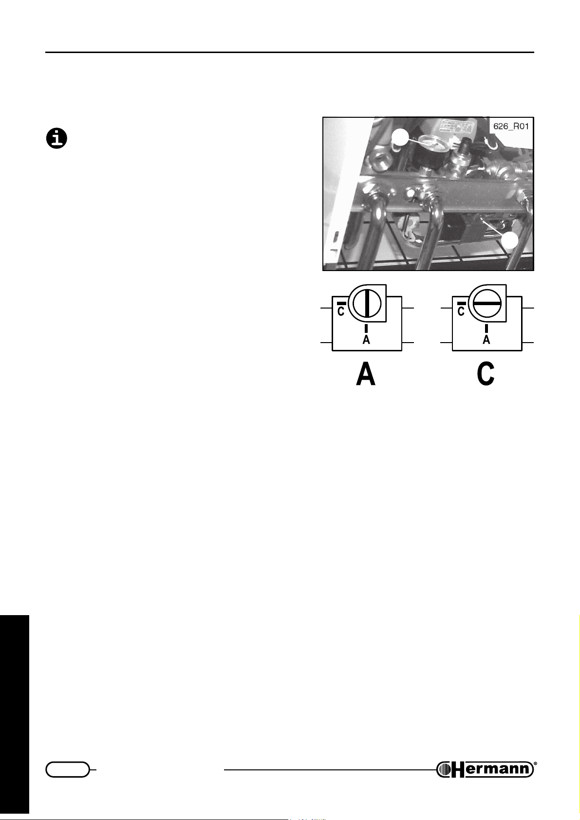
Installation instructions
System filling
Once the boiler is hydraulically connected, it is
possible to fill the system.
BOILER BOTTOM VIEW
Warning: if boiler is installed in a room where
temperature can drop below 0°C, it is
recommended to fill the heating system with
an anti freezing mixture.
While filling, please follow carefully the following
phases:
— Open air vent in radiators;
— open filling tap;
— slowly unscrew screw [2] located in water filling
electro-valve, from position “C” to position “A” (see
picture), taking care of all air vent installed in the
system;
— as soon as water flows out of air vent radiators,
close air vents;
— check on the manometer [1] that pressure reaches
the optimal value of 1÷1.5 bar (minimum: 0.5 bar),
then reset screw [2] in position “C” (closed);
1
2
627
— repeat previous operations until all air in the system has been blown out.
Note: Boiler is equipped with a special automatic filling device, which automatically fills boiler to
reset its pressure provided that boiler is electrically fed.
for the technician
12
Page 13
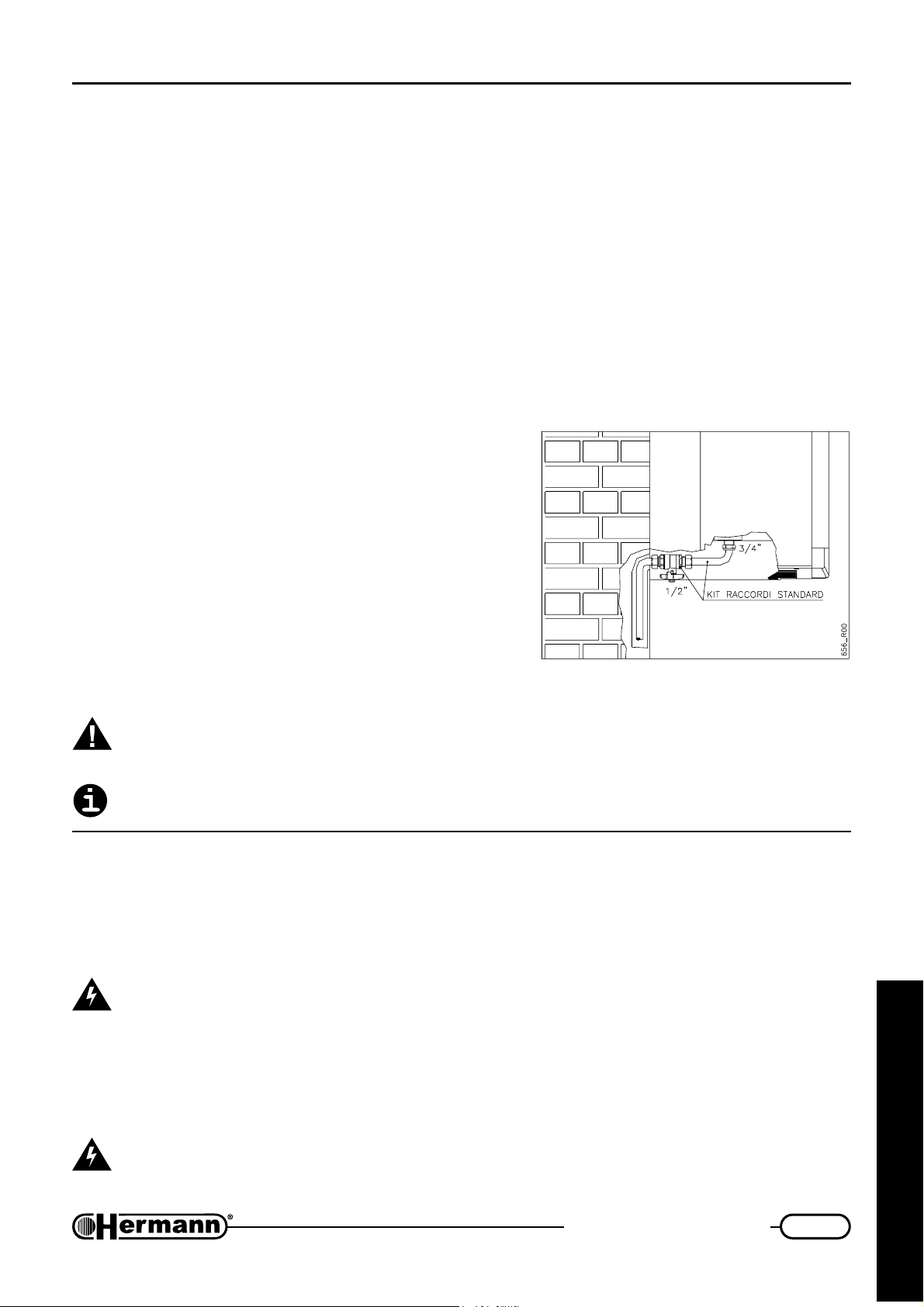
Installation instructions
Gas connection
Remark: If gas cock position is foreseen near the WALL, install first gas cock, then water inlet tap.
Boiler installation must be carried out from a qualified technician, [exemple: as indicated by the Law
XXXXX] because an incorrect installation can cause damages to people, animals or things, for
which the manufacturer cannot be held responsible.
Verify what follows:
a) cleaning of all system gas pipes in order to avoid the presence of residual combustion products
that could compromise the correct boiler functioning;
b) gas line and ramp conformity with laws and rules actually in force (exemple: Laws UNI-CIG
7129/01, 7131/99 - DM 12/04/96);
c) internal and external tightness of the gas system and
connections;
d) supply pipe must have a section greater than or equal
to the boiler one;
e) supply gas must correspond to the one for which the
boiler has been regulated; otherwise, call [a
HERMANN Service Centre] [a qualified technician]
for gas conversion;
f) an interception valve must be installed upstream the
appliance;
Open the meter valve and purge the air that is inside the system pipes (including all the appliances).
While connecting gas inlet pipe of the boiler to the pipe coming from gas network, it is
MANDATORY to insert a TIGHT GASKET, whose dimensions and material must be
adequate. Connection is NOT suitable for hemp, teflon strip or similar materials.
Using LPG, it is absolutely necessary to install a pressure reducer upstream the boiler.
CONNECTION EXAMPLE
Electrical connections
GENERAL WARNINGS
The cable for electrical supply must be connected to an electrical line of 230V-50Hz, respecting the
polarities L-N (Live-Neutral) and the earth connection.
PLACE UPSTREAM THE BOILER A BIPOLAR SWITCH in accordance with the rules
actually in force.
For the general electrical supply of the appliance, the use of adaptors, multiple taps and extensions
is not allowed.
It is mandatory the earth connection in accordance with the CEI rules actually in force.
Electrical safety of the appliance is only achieved when it is well connected to an
efficient earthing system, executed as indicated by the safety rules actually in force.
for the technician
13
Page 14
Installation instructions
A qualified technician must check that the electrical system is in line with the maximum power
allowed by the boiler, indicated on the data plate, with particular attention to the cables section.
Remark: HERMANN Ltd. declines any responsibility for damages to persons, animals or
things caused by the non-connection of the boiler earthing and by failure to comply with
the rules.
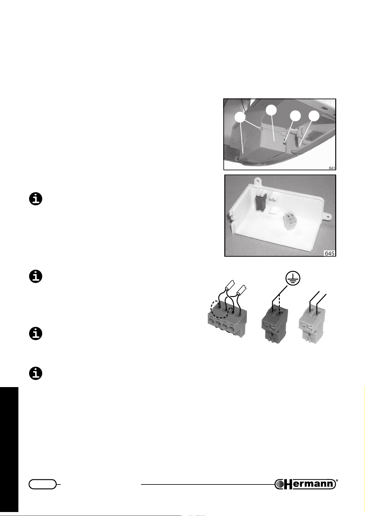
ELECTRICAL CONNECTIONS TO THE BOILER
— Unscrew the two screws [1] and remove cover [2];
— extract yellow and white connectors;
— make electric connections as shown in the picture
situated on the other side of the cover:
• connect earth wire to yellow connector;
• connect NEUTRAL cable (N) and PHASE (L)
to WHITE connector, precisely as shown in
the picture;
If PHASE and NEUTRAL wires are reversed,
the boiler will not work.
2
1
3
4
• when a Room Thermostat or Chrono
Thermostat (TA) and/or Outdoor Temperature Probe (SE) are foreseen, unplug GREEN
connector from PCB and make connections
as shown in the picture. If TA is installed,
disconnect jumper [X].
TA and SE terminals on green connector work
at low voltage: only connect NON POWERED
wires coming from simple contact of Room
Thermostat / Chrono Thermostat, and/or
Outdoor Temperature Probe. DO NOT connect
live wires, for any reason.
Original Hermann remote control (optional kit)
must NOT be connected to green connector.
Special interface card, supplied in the remote
control kit, must be used.
All low-voltage wirings (e.g. TA, SE and original Hermann remote control) must be kept sepa-
for the technician
rate from power supply cables, as to avoid boiler malfunctionings due to electrical noise. It is
advisable to use separate tubes for them.
X
642_R01
TA
SE
L
N
— all the relevant connections must be inserted in modulation PCB, FOLLOWING THE CORRECT
COLOURS. They have been provided with special plugs for correctly connect them.
— close cover inserting cables in the provided holes [3] and screw the screws [1];
— block cables with the special device [4].
14
Page 15
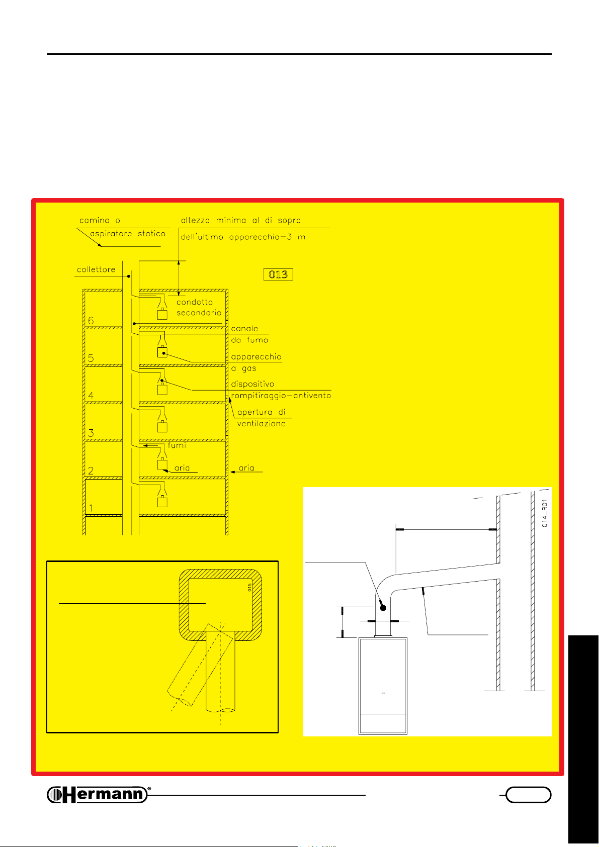
Installation instructions
Chimney connections
EURA E
CHIMNEY CONNECTIONS of OPEN chamber boilers
(natural draught)
Place here all necessary
advices according to national rules about
These diagrams are
to explain the most
important ITALIAN
laws concerning
chimney connections
FLUE
PRODUCTS TEST POINT
2 x d
min
(for EXAMPLE
purpose only)
2500 mm MAX
d
SLOPE
min 3%
for the technician
NO YES
15
Page 16
Installation instructions
Chimney connections
EURA SE
NOTE ON FLUE INSTALLATION
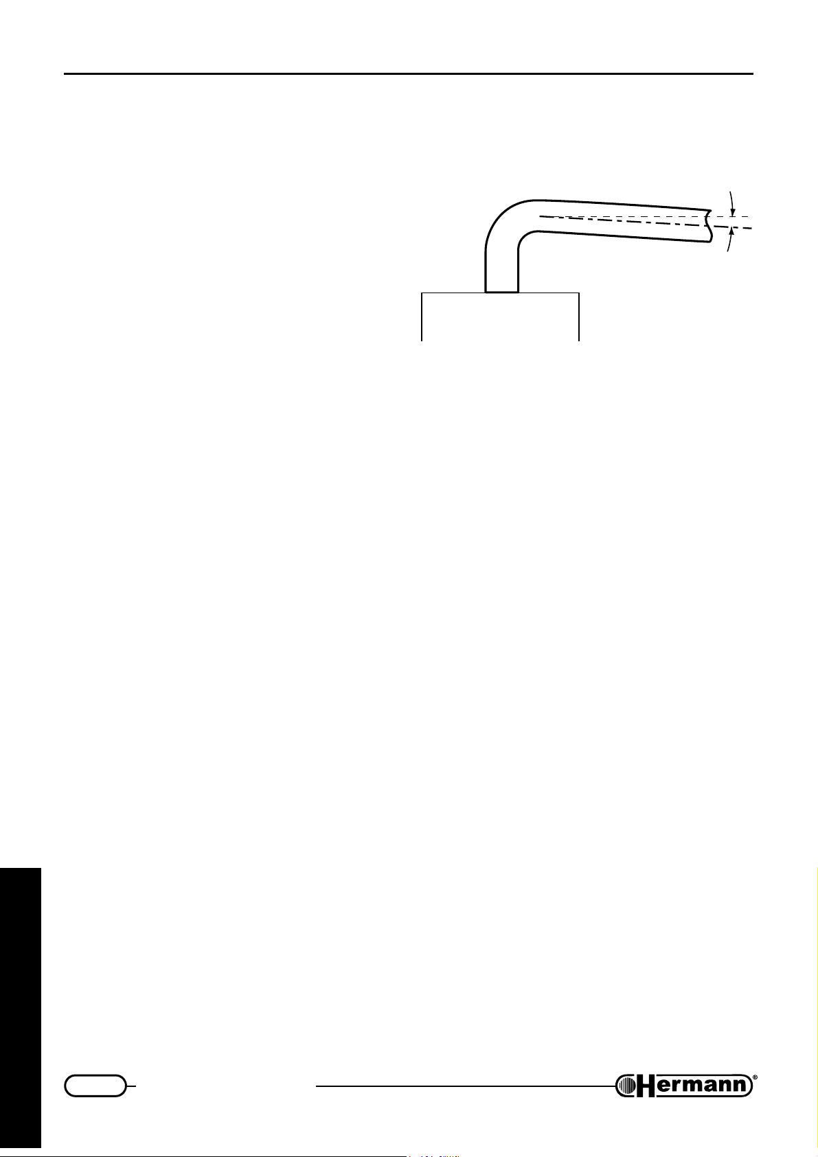
When fitting air inlet and flue outlet horizontal
ducts, it is necessary to make sure there is a slope
of 2÷5% downwards from the boiler to the outside (see diagram). This is essential to guarantee correct boiler operation and reliability. Air inlet and flue outlet terminals should be protected
by suitable approved flue accessories, to avoid
environmental elements penetration.
(forced draught)
Place here all necessary
advices according to national rules about
CHIMNEY CONNECTIONS of SEALED chamber boilers
2% ÷ 5%
631R01
for the technician
16
Page 17
Installation instructions
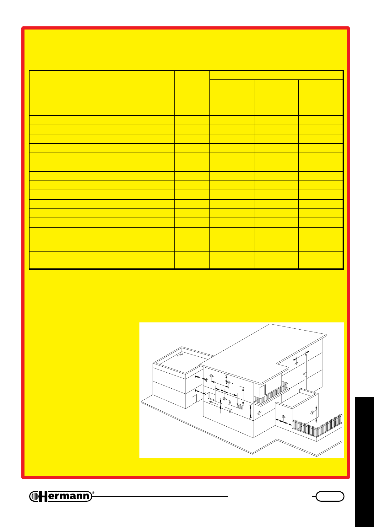
In case of evacuation to wall, the positions indicated in the following drawing and table must be
respected:
tupnitaehriehtnognidneped,sreliobthguarddecrofrofslanimreteulffogninoitisoP
secnailppA
gninoitisoplanimreTsecnatsiD
*Wk4morf
Wk7ot
mm
.nim
Wk7morf
Wk61ot
mm
.nim
wodniwarednUA003005006
tnevrianarednUB003005006
rettugarednUC003003003
**ynoclabarednUD003003003
wodniwtnecajdanamorFE004004004
tnevriatnecajdanamorFF006006006
***sepipnoitaucavelatnozirohrolacitrevmorFG003003003
gnidliubehtforenrocamorFH003003003
gnidliubehtfosseceramorFI003003003
roolfrehtonamorfrodnuorgehtmorFL004 0051 0052
yllacitrevslanimretowtneewteBM00500010051
yllatnozirohslanimretowtneewteBN0050080001
ongnivah,ecafrusrehtonagnicafecafrusamorF
.stm3foecnatsidanihtiwslanimretrosgninepo
O005100810002
elohnoitaucaveehtmorf
nihtiwslanimretrosgninepohtiwtub,evobasA
elohnoitaucaveehtmorf.stm3foecnatsida
P005200820003
Wk61morf
Wk53ot
mm
.nim
* Appliances with an heat input lower than 4 Kw are not subjected to any limitation for the terminals
positioning, except for the points O and P.
** The terminals under a practicable balcony must be positioned in such a way that the total flue run, from
the terminal outlet to its own outlet from the external balcony perimeter, included the height of the
eventual protection banisters, is no lower than 2000 mm.
*** In the terminal positioning, it will
be necessary to keep
distances not inferior to 500
mm. in case of close proximity
to materials sensible to the
G
combustion products action
(e.g., plastic gutters and
downpipes, wood projections
and so on), unless adequate
measures of protection have
been adopted.
The terminals must be
designed in such a way that the
O
P
C
N
E
F
M
A
B
D
I
H
L
combustion products flow is as
much as possible ascensional
and protected from the temperature effects.
for the technician
17
Page 18
Installation instructions
High capacity fan
EURA 23 SE
For EURA 23 SE (forced draught) it is possible to install, on request, an “high capacity fan”, allowing
an higher length of separate flue systems (see table):
Øtelniria/teltuostcudorpeulfetarapeS mm08
htgneleulfetarapeS m)ociracs02xam(03
nafyticapachgihhtiwhtgneleulfetarapeS m)ociracs04xam(06
ASSEMBLING INSTRUCTIONS
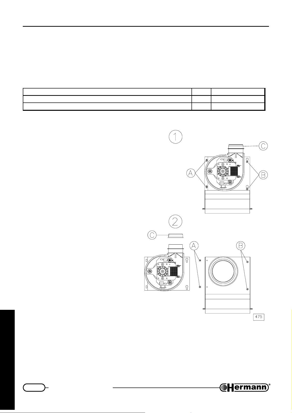
It is advisable to install the high capacity fan,
before flue kit, avoiding any possible hindrance
during assembling operations.
Provide electrical disconnection of the gas
boiler and remove the sealed chamber closing;
1. Take off screws A, loosen screws B (it is
not necessary to take off screws B, being
the fan bracket provided with button-holes)
and remove the standard fan,
disconnecting its cables for electrical
supply; remove the flue pressure sensor.
2. Remove gasket C from standard fan and
insert it on high capacity fan; install the
flue pressure sensor, respecting its
previous position.
Install the high capacity fan, connect the
cables for electrical supply, tighten screws B
and reinsert screws A.
Reassemble the sealed chamber closing.
for the technician
18
Page 19
Installation instructions
Flue options
EURA SE
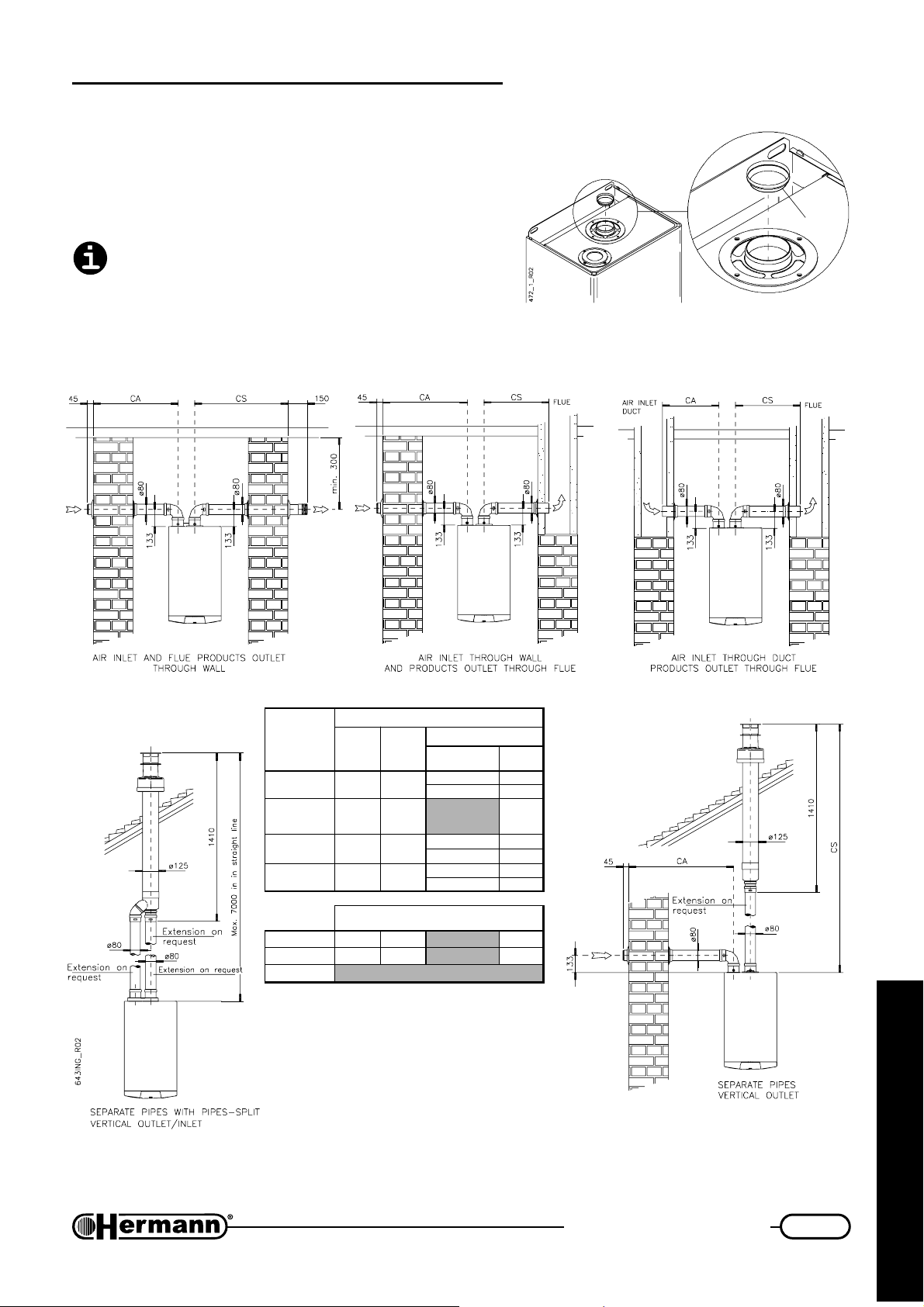
AIR INLET AND PRODUCTS OUTLET THROUGH
SEPARATE PIPES
Attention: see table and, if required, install the
diaphragm “D” as indicated in the figure besides
(any additional 90° bend = 0.5 linear meters, 45°
bend = 0.25 meters).
D
SC+AC
ledoM
ES32 03÷2 02
ES32
hgihhtiw
nafyticapac
ES82 52÷2 02
ES23 02÷2 21
ES32 41÷2 31 ON
ES82 41÷2 7 ON
ES23 elbissoptoN
(d) use the diaphragm supplied with the boiler.
SC
xam÷nim
xam
)m(
)m(
06÷13 04 ON
stcuddetarapesmm08Ø
fohtgneL
)m(SC+AC
8otpu )d(
8nahterom ON
8otpu )d(
8nahterom ON
6otpu )d(
6nahterom ON
stcudmm08Ø
mgarhpaiD
retemaid
)mm(
noitcennoclaixaocnorettilpSsepiPhtiw
for the technician
19
Page 20
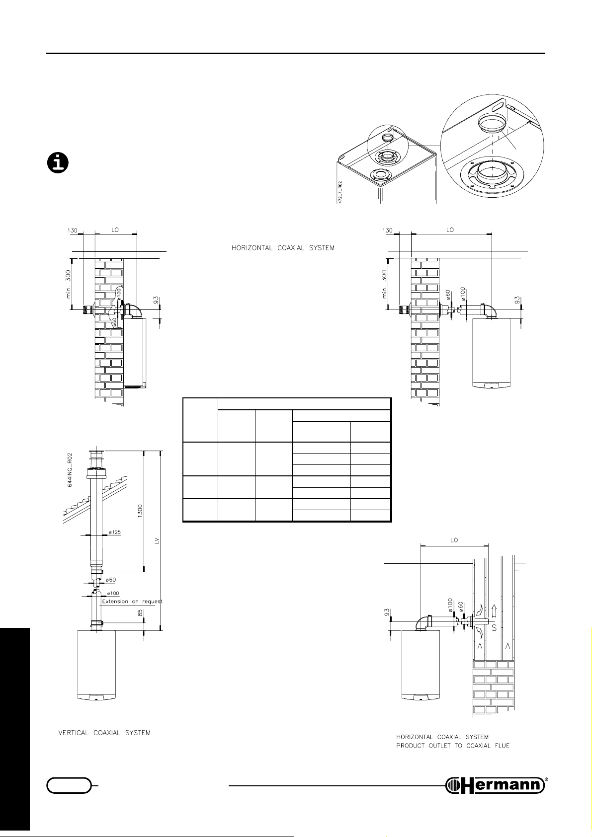
Installation instructions
Flue options
EURA SE
AIR INLET AND PRODUCTS OUTLET THROUGH
COAXIAL SYSTEM
Attention: see table and, if required, install the
diaphragm “D” as indicated in the figure besides
(any additional 90° bend = 1 linear meter, 45°
bend = 0.5 meters).
ledoM
ES42 4÷5.0 5÷1
ES82 3÷5.0 4÷1
ES23 3÷5.0 4÷1
(d) use the diaphragm supplied with the boiler. (b) available on request.
OL
)m(
VL
xam÷nim
xam÷nim
)m(
metsyslaixaoc001/06Ø
mgarhpaiD
VLroOL
)m(htgnel
1otpu )b(44
2ot1 )d(
2nahterom ON
1otpu )d(
1nahterom ON
1otpu )d(
1nahterom ON
D
retemaid
)mm(
for the technician
20
Page 21
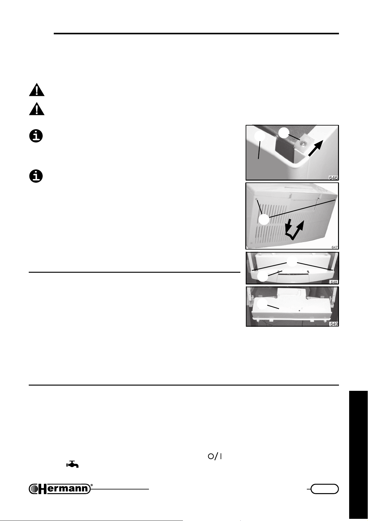
First firing, regulation and servicing instructions
FIRST FIRING, REGULATION AND
SERVICING
ATTENTION: the operations described below must be carried out only by qualified
personnel [authorized by HERMANN].
When regulation/measuring is over, remember to tighten pressure tapping point screws
and ALWAYS check for gas leaks!
Before boiler ignition, verify that pump is not blocked due to
its inactivity: unscrew the plug located in the middle of the
cap to gain access to the rotor shaft, and turn it manually
using a screwdriver or another suitable tool.
During the first ignition of the brand new boiler, it is necessary
that burner works for at least 30 minutes, before performing
combustion checks. During this time, the fumes of the eventual
residual manufacturing materials are produced, and they could
alter the measured values.
Note: When boiler is electrically connected (or is ignited) it is
necessary to wait about 90 seconds before having the complete control of the boiler. Such delay can be temporary excluded
through programming parameter n° 9 (see “Regulation
programming”) and it must be activated to guarantee perfect
boiler working.
INSTRUCTIONS
2
3
1
4
5
Gaining access to
manual regulation devices
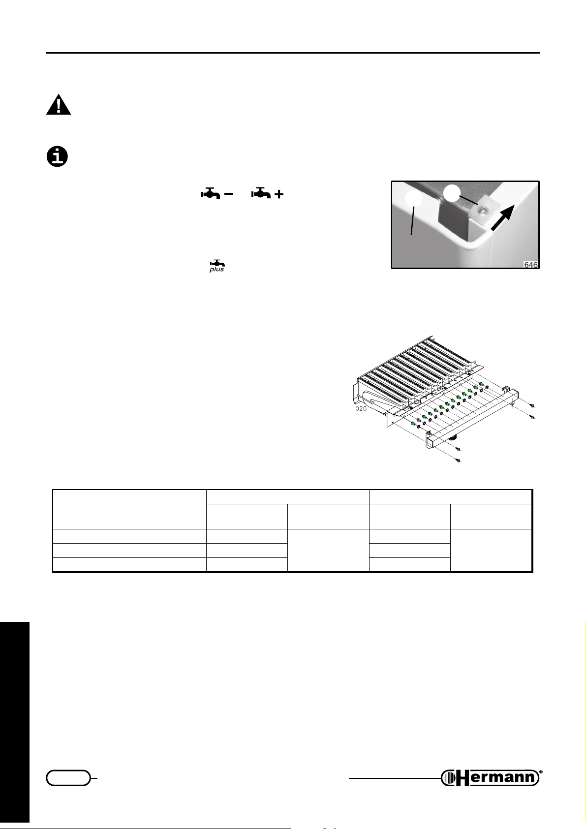
1. Unscrew screws located above boiler, shift small blocking plate
1, remove front cover 2 lifting it up.
2. To remove lower grid, if any, unscrew screws [3], push, lower and shift it forward.
Note: lower grid is spare inside packing, not assembled.
3. Unscrew fixing screws [4] and extract control panel [5] forward, rotating it around hinges.
4. Once regulation are over, reverse perform steps from 3 to 1.
5
Preliminary gas control
All boilers are tested and factory set during manufacture; however, it is advisable to check that the
gas type and the burner pressures are correct. Follow the procedures described in this section.
— All connections to boiler (water, gas, heating system and electricity) must work. Green light on,
yellow and red light off.
— Open control cover and turn boiler on by pushing
symbol appears with its requested (set) domestic water temperature.
knob. Green light on, on to display
for the technician
21
Page 22
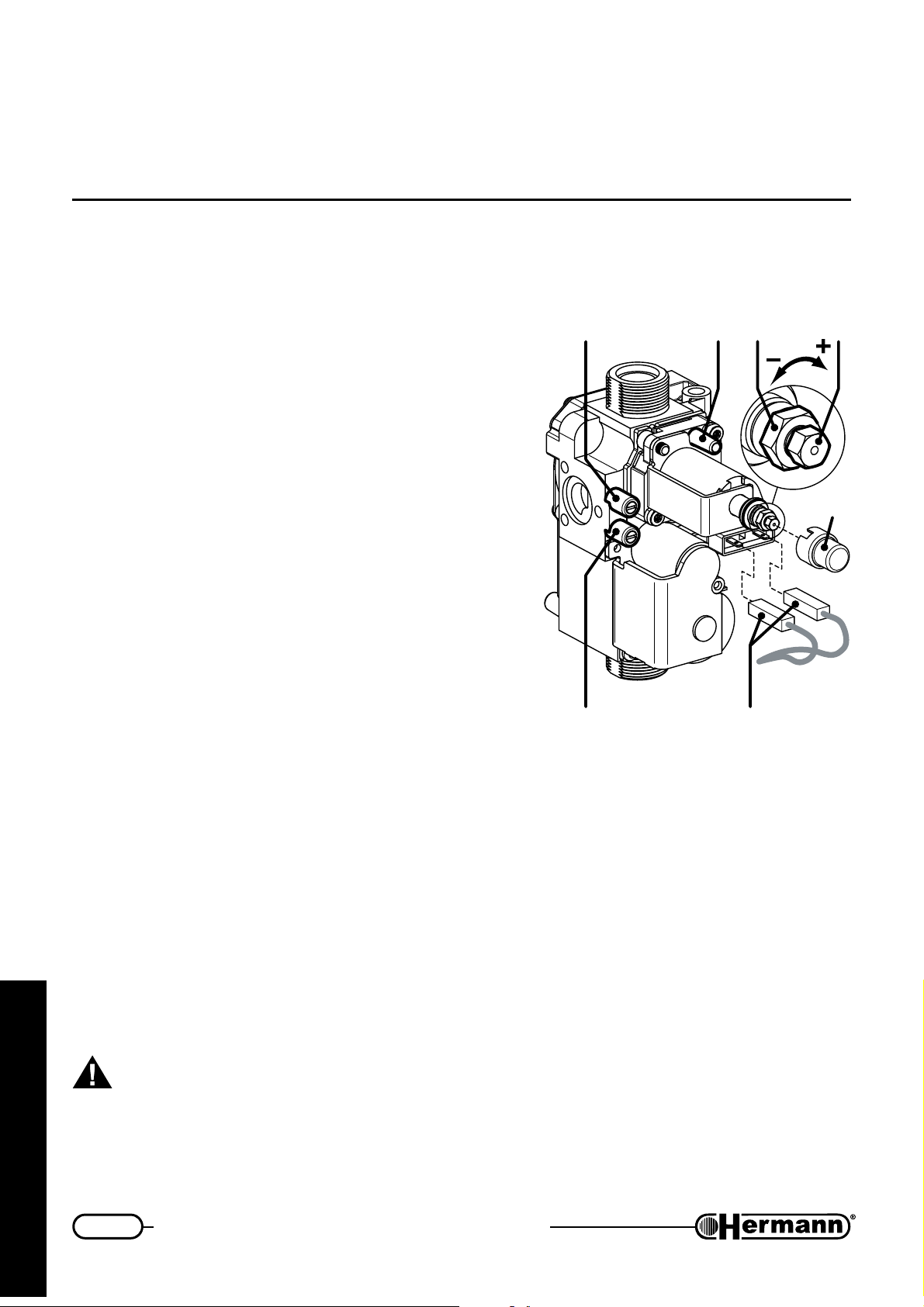
First firing, regulation and servicing instructions
— To make gas pressure controls, insert manometer probes in pressure tapping points available
on to gas valve (see picture).
Note: To check that gas pressure and flowrate are sufficient to guarantee perfect boiler operations,
make such controls while burner is working.
MAX-MIN pressure adjustment
on GAS valve
GAS VALVE
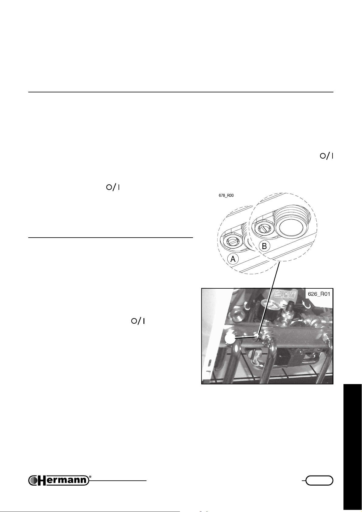
— Unscrew (2-3 rounds) the screw in outlet pressure tap-
ping point [1] on gas valve and plug in manometer
probe. On “SE” models, unplug silicon rubber pipe (coming from sealed chamber) from “Vent” plug [3];
— start the boiler at maximum power (not modulating)
proceeding
check” paragraph; as alternative, proceed as follows:
• set the domestic hot water temperature to the
maximum value;
• open an hot water tap fully (flow rate 10 l/minute,
open more than one tap if needed), wait for the
stabilization of the pressure (at least 20 seconds);
preferably
as described in “Combustion
1BA
3
C
— verify that pressure correspond to the MAX value indi-
cated in the table “BURNER POWER / PRESSURES”
(see following pages);
— unplug one of modulation coil supply connectors [4]
and check that pressure correspond to the MIN value
indicated in the table “BURNER POWER / PRESSURES”, then plug the connector back in;
— if it is necessary to adjust settings, proceed as follows,
according to the figure:
• remove protection cap [C];
• adjust MAX pressure by turning bigger nut [B] (8 mm). Clockwise to increase pressure,
counterclockwise to decrease;
• unplug again one of connectors [4];
for the technician
• adjust MIN pressure by turning smaller nut [A] (5 mm) while keeping bigger nut [B] stopped.
Clockwise to increase pressure, counterclockwise to decrease;
• insert connector [4] again and check that MAX pressure is not changed;
• Fit cap [C];
872_R00
24
Pressure tapping pionts:
1 = Gas OUT
2 = Gas IN
3 = “Vent” plug (SE models)
Important: lock the adjustment device after any setting operation.
22
Page 23
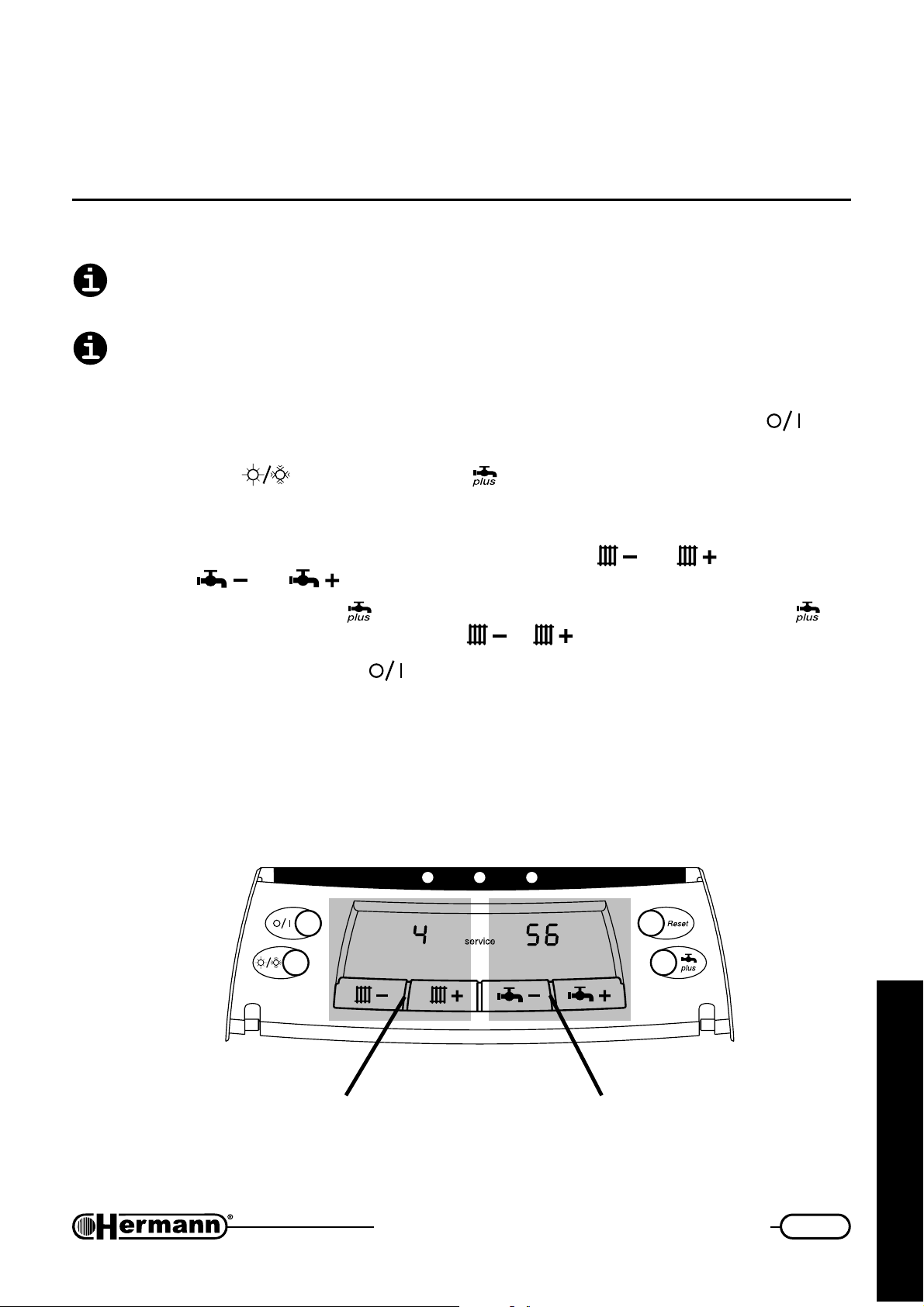
First firing, regulation and servicing instructions
— On “SE” models, plug silicon rubber pipe on “Vent” plug [3] on gas valve. WARNING: after
plugging the pipe on “Vent” plug, the value on manometer may decrease due to pressure compensation. This is normal and doesn’t require any further adjustment;
— fully screw outlet pressure tapping point screw [1] and check for gas leaks.
Regulation programming
All these operations must be performed by QUALIFIED TECHNICIANS ONLY. Operations
performed by not qualified persons can cause MALFUNCTIONS and/or DAMAGE. Hermann
cannot be considered liable for eventual damages caused by not qualified persons.
Do not modify default settings if not necessary
GENERAL PROCEDURE
— With control panel in normal position, open its cover and turn off boiler pushing
green light flashes:
— Keep both knobs
shows “service” with a number on the left (from here on called ‘PARAMETER’) and another
number on the right (from here on called ‘VALUE’);
— Select number of PARAMETER to be modified pushing knobs
by pushing and .
— To STORE a new value push
simply select another parameter (by pushing or ).
— To quit programming mode push
(Summer/Winter) and pushed for 5 seconds contemporary: display
and ; change VALUE
. If you want NOT to store the value, do NOT push but
.
knob:
Note: Once quitted program mode, it is necessary to wait about 90 seconds for complete motorised
mixing valve calibration. Such delay can be temporary excluded through programming parameter
n°9 described here below.
630A
To select the
PARAMETER
for the technician
To edit the
VALUE
23
Page 24
First firing, regulation and servicing instructions
Parameter numbers, description, available values and default settings:
1 Gas type: Natural gas = 0 / LPG = 1. Default setting: 0. See “GAS transformation” for the
complete regulation procedure.
2 Temperature range for heating system: Normal = 0 / Reduced = 1. Default setting: 0.
Leave default setting unchanged.
3 Gas pressure* during slow opening: from 00 to 99. See ‘Slow opening regulation’ for
default setting (they may be different depending on boiler model and/or gas type) and for
complete regulation procedure.
4 Maximum heating power gas pressure*: from 00 to 99. Default setting: 99. See ‘Maximum
heating power regulation’ for the complete regulation procedure.
* = All values shown on to display are NOT gas pressure values and must be considered
for indication only. All correct gas pressure values must be verified through a micro
manometer correctly calibrated
5 Pump working in Winter mode: Normal = 0; Always on = 1; Always off = 2. Default
setting: 0. See ‘Other boiler programming’ for more info.
6 Switching on delay after reaching set heating temperature: from 0 to 7 minutes. Default
setting: 3. See ‘Other boiler programming’ for more info.
7 Temperature difference between heating flow and domestic set: from 10 to 20 °C.
Default setting: 15°C. We advice to leave default setting unchanged.
8 Minitank temperature setting according to dhw temperature setting: 0, 1, 2 and 3.
Default setting: 0. See “Other boiler programming” for more info.
Parameters 7 and 8 allow to optimise comfort level of the domestic hot water system,
according to water hardness. It is recommended to keep these values to default setting,
especially in case of hard water, unless a suitable scale reducing device is fitted.
9 Ignition delay for motorised mixing valve calibration: Activated = 0 - Excluded = 1.
Default setting: 0. See ‘Other boiler programming’ for more info.
It is MANDATORY that parameter n° 9 is set = 0 for normal boiler functioning.
10 External probe indication (not modifiable): No probe / disconnected = 0; Probe detected
= 1. See ‘Other boiler programming’ for more info.
for the technician
24
Page 25
First firing, regulation and servicing instructions
Slow opening regulation
When boiler is ignited, burner is fed for 8 seconds with a
gas at a lower pressure then usual; afterwards pressure
increases up to requested values. Such ‘slow opening’
pressure must guarantee correct and immediate ignition
avoiding noises while igniting.
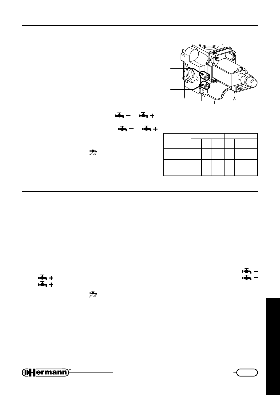
— Loosen (2 – 3 rounds) screw of gas valve pressure
hole (part 1 figure ‘Gas valve’) and connect
manometer;
GAS VALVE
873_R00
1
2
— while boiler is not working (green light flashing), select
parameter 3 and push once knob
or .
Burner will ignite allowing slow opening regulation. To
correct values shown, push knobs or
until correct values are reached. (Correct, default
values are shown in the here attached table);
— store pressure pushing
;
— should you regulate heating power (mandatory for first
ignition), proceed to next phase. Otherwise, remove
gas probe, screw the relevant screws and verify gas
Pressure tapping pionts:
1 = Gas OUT
2 = Gas IN
gninepowolS 02GsaglarutaN13G/03GGPL
ledomrelioBrabm
E32ARUE5.3530382874
E82ARUE5.3530382874
ES32ARUE717744134106
ES82ARUE717744134106
ES23ARUE515244134126
mm
yalpsiD
.a.c
eulav
mm
rabm
.a.c
eulav
leakage.
Max heating power
regulation
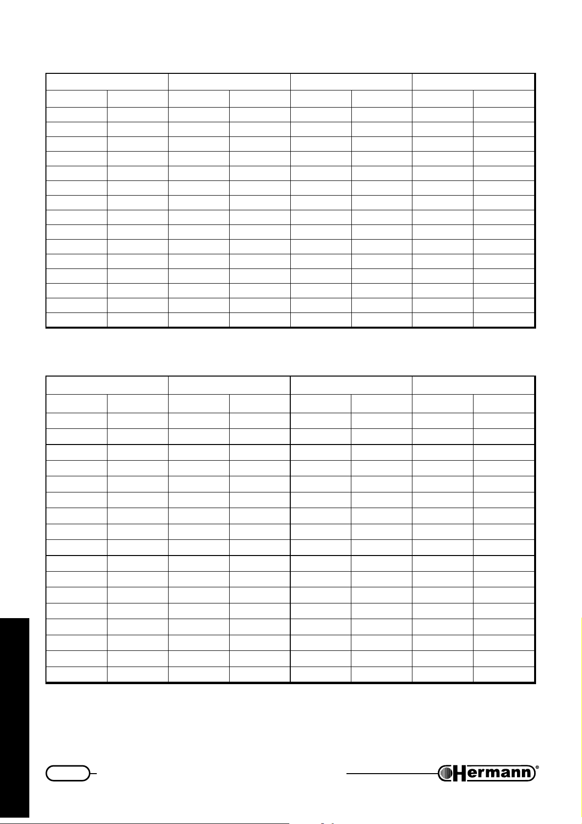
Maximum heating power must be set according to actual heating system design. Please find herewith
table with power/gas pressure values. To regulate heating output proceed as follows:
— Actual heating system power must be known according to plant design;
yalpsiD
— unscrew (2-3 rounds) screw of gas valve pressure hole (part 1 figure ‘Gas valve’) and connect
manometer;
— while boiler is not working (green light flashing), select parameter 4 and push once knob
or . Burner will ignite allowing maximum heating power regulation. Push knobs
or until correct value is reached;
— store pressure pushing
;
— remove gas probe, screw the relevant screws and verify gas leakage.
25
for the technician
Page 26
First firing, regulation and servicing instructions
BURNER POWER/PRESSURE TABLE — EURA 23 E
TUPTUOTAEH02GSAGLARUTAN03GENAHTUB13GENAPORP
Wkh/lackrabmHmm
30.9.NIM00772.2225.464515
0100686.2625157.585
1106490.3037.5857.686
21023014.3537.6869.708
31081117.3835.777929
41040215.4649293.21521
51009215155.017015.41841
61067315.5655.2172161361
71026411.626510513.81681
81084515.6663.616613.02702
91043612.7376.8109132432
020027189024022.52752
12060816.888224225.72082
220298101201525525.03113
1.32.XAM003023.215215.720825.43053
OrabmHmm2OrabmHmm2O
2
BURNER POWER/PRESSURE TABLE — EURA 28 E
Wkh/lackrabmHmm
0.11.NIM03695.2525156 16
21023010.3032.7279.819
31081116.3737.89801201
41040212.4348.90018.21031
5100921515112115.41841
61067316.5758.1102161361
71026412.636312318.71181
81084517179.4125102402
91043616.777613615.22922
02002713.8488.7118142442
12060819295.918915.62072
22029815.9797.0211282582
for the technician
32001021.013019.123224.92003
42046026.018015.329322.13813
52005122.114118.423526.23233
62063228.110219.5256243743
TUPTUOTAEH02GSAGLARUTAN03GENAHTUB13GENAPORP
OrabmHmm
2
OrabmHmm
2
0.82.XAM015426.218215.7208253753
O
2
26
Page 27
First firing, regulation and servicing instructions
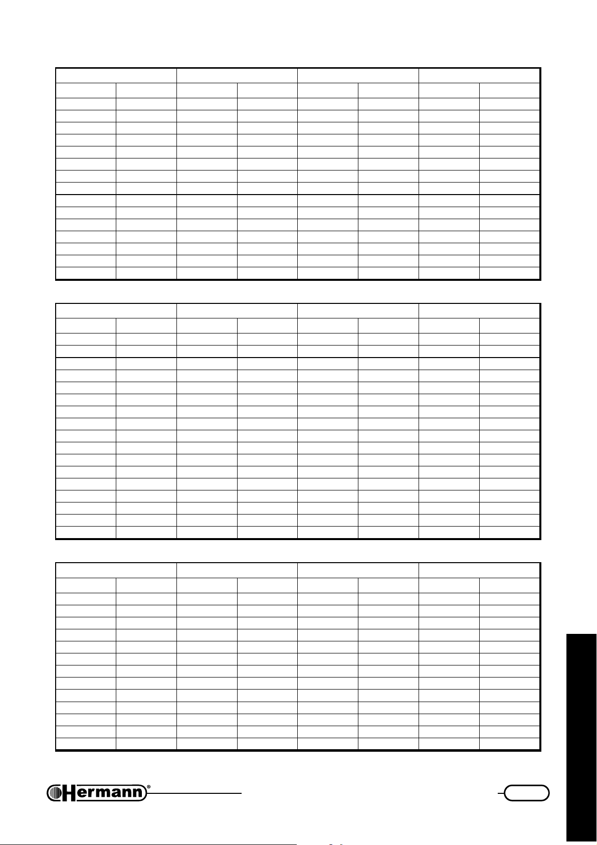
BURNER POWER/PRESSURE TABLE — EURA 23 SE
TUPTUOTAEH02GSAGLARUTAN03GENAHTUB13GENAPORP
Wkh/lackrabmHmm
70.9.NIM20872.2229.4059.405
0100686.2629.5067.585
1106490.3030.7177.686
21023014.3532.8489.708
31081117.3835.979929
41040215.4649.011113.21521
51009215153.215215.41841
61067315.5658.3114161361
71026411.6263.516513.81681
81084515.6669.613713.02702
91043612.7376.8109132432
0200271893.027022.52752
12060816.8881.225225.72082
2202981012019.324425.03113
7.32.XAM083023.215212.727725.43053
OrabmHmm2OrabmHmm2O
2
BURNER POWER/PRESSURE TABLE — EURA 28 SE
TUPTUOTAEH02GSAGLARUTAN03GENAHTUB13GENAPORP
Wkh/lackrabmHmm
2.11.NIM03696.2625156 16
21023010.3032.7279.819
31081116.3737.89801201
41040212.4348.90018.21031
5100921515112115.41841
61067316.5758.1102161361
71026412.636312318.71181
81084517179.4125102402
91043616.777613615.22922
02002713.8488.7118142442
12060819295.918915.62072
22029815.9797.0211282582
32001021.013019.123224.92003
42046028.010115.329322.13813
5200512212218.423526.23233
62063225.217219.5256243743
5.82.XAM015422.314315.7208253753
OrabmHmm2OrabmHmm2O
2
BURNER POWER/PRESSURE TABLE — EURA 32 SE
TUPTUOTAEH02GSAGLARUTAN03GENAHTUB13GENAPORP
Wkh/lackrabmHmm
4.11.NIM06798.1813.5458.696
21023010.2027.5853.757
41040217.2725.7777.999
61067315.3635.9792.21521
81084514.4547.119119.41251
02002714.5550.413419.71281
22029814.6664.617619.02312
42046026.7879.812911.42542
62063229.8094.129123.72972
82080422.014011.426427.03313
03008526.119118.623721.43843
3.13.XAM02962——8.724824.53163
7.13.XAM042727.21921 ————
OrabmHmm2OrabmHmm2O
2
for the technician
27
Page 28
First firing, regulation and servicing instructions
Gas transformation
ATTENTION: the operations described below must be carried out only by qualified
personnel [authorized from HERMANN Ltd].
For gas conversion, use the nozzles supplied by boiler manufacturer only.
Using LPG, it is absolutely necessary to install a pressure reducer upstream the boiler.
1. while boiler is not working (green light flashing), select
parameter 1. Push knobs
to:
0 for natural gas working
1 for LPG working
or according
2
1
and store pressure pushing
;
2. Check that pressure and gas input are enough to
guarantee the correct functioning of the appliance.
3. Disconnect the boiler from the supply.
4. Remove front cover: unscrew screws located above
boiler, shift small blocking plate [1], remove front cover
[2] lifting it up. On “SE” models, open sealed combustion
chamber.
5. Disassemble pipe connecting Gas valve with burner.
6. Remove ramp containing nozzles and substitute it with
correct one, using a 7mm spanner. Reassemble ramp
and pipe, substituting gaskets. On “SE” models, close
sealed combustion chamber.
LEDOM
ES/E32ARUE31021
ES23ARUE5103177
forebmuN
selzzon
ØselzzoN
)mm001/1(
02GSAGLARUTAN13G/03GGPL
02
RAMP AND NOZZLES
REMOVAL
erusserpsaG
)rabm(
ØselzzoN
)mm001/1(
57
erusserpsaG
)rabm(
73/03ES/E82ARUE5102157
7. Check, with burner ON, that there are no gas leaks and that the pressure upstream the boiler
is:
for the technician
Natural gas: min.17 – max. 25 mbar
Buthane: min. 25 – max 35 mbar
Propane: min. 25 – max 37 mbar
28
Page 29
First firing, regulation and servicing instructions
8. Repeat the following regulations: gas valve MAX-MIN pressure regulation, Slow Opening and
Max Heating Output, carefully following the instructions described in the previous pages.
9. Check that there are no gas leaks.
10. Apply the sticker indicating the type of gas (supplied with the kit) on the suitable area on “WARNING” label inside the boiler.
Combustion check
EURA has a special function for allowing flue checks. During this mode burner works at maximum
power regardless room thermostat and sanitary system.
— Prepare instrumentation for flue checking;
— while boiler is working (either in Winter or in Summer mode) keep knobs ‘Reset’ and
pushed for 10 seconds. Boiler will ignite at maximum power and in the center of the display will
appear the code “07”. Heating will be flown to heating system;
— to stop burner press
Note: Burner will automatically switch off when heating
system inlet temperature reaches 85°C. However,
after 15 min boiler will exit ‘programming mode’
and burner will stop.
;
Excluding automatic bypass
EURA are equipped with automatic by pass. In case
of complete opening, a flowrate sufficient for normal
boiler working is guaranteed. However, it is possible
to disconnect by pass, proceeding as follows:
1. Switch off boiler by pressing
2. Rotate screw located on to by pass (see 1 in the
attached picture) until it is in position “B”.
Normal by pass position is “A”.
.
1
for the technician
VISTA DAL BASSO DELLA CALDAIA
29
Page 30
First firing, regulation and servicing instructions
Draining EURA boiler
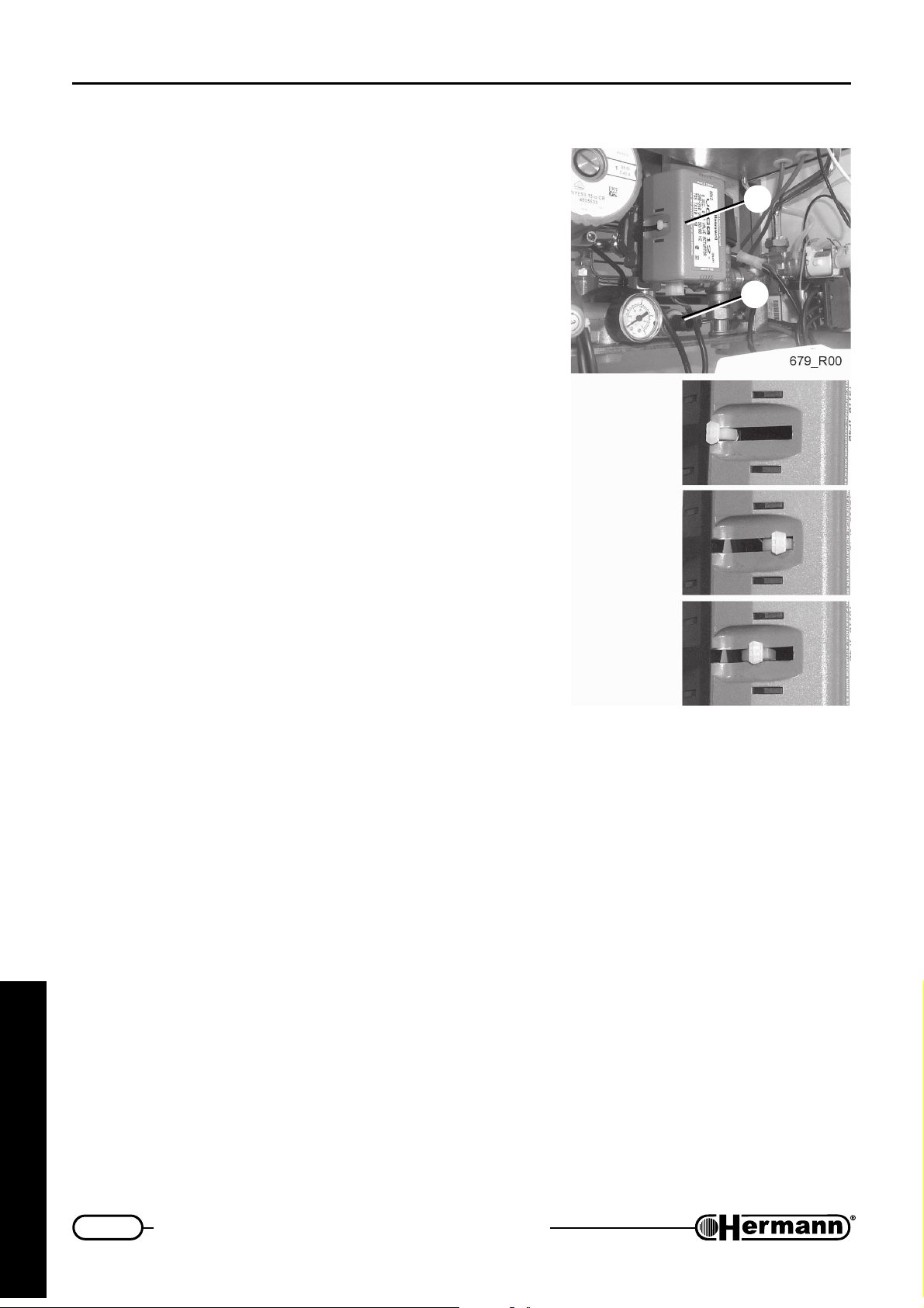
— To correctly drain both heating system and minitank in
the sanitary system, it is necessary to manually set three
way valve in middle position as described here below:
• three way valve (item 3) must initially be in ‘sanitary’
mode (manual control spindle in position ‘S’). If it is
in position ‘R’, open a domestic hot water tap to move
it to ‘S’;
• switch boiler off;
• manually push spindle towards middle position,
where it can be blocked pushing towards inside
(position ‘C’).
3
2
— Connect a rubber pipe to the draining tap [2] terminal;
— put the other end of the pipe in a suitable drain or sink;
— open draining tap anticlockwise;
— when water pressure is COMPLETELY drained, you can
open radiators air vents, to allow air inlet and complete
plant draining;
— when everything is over, close taps and air vents.
R
S
C
for the technician
30
Page 31

First firing, regulation and servicing instructions
Other boiler programme
Above have been described the main regulations, and most of them require some parameters
programming by means of control panel.
Control panel allows to modify many other parameters which influences boiler functioning, for perfectly
meeting special installation needs.
Do not modify default settings if not necessary
2 Heating system flow temperature range: (default value = 0):
This parameter must always be set at 0
5 Pump working in winter mode: (default setting = 0):
0 NORMAL: pump switches on whenever there is a heating demand and keeps on working
for all requested time plus 30 seconds (after circulation).
1 ALWAYS ON: In Winter mode pump continuously works. Use this setting only if it is requested
by heating plant.
2 ALWAYS OFF: In Winter mode pump is not activated (it works only if there is a request of
sanitary water). Use this setting only if external pump(s) are installed.
6 Delay before re-ignition after reaching heating flow temperature set: (in minutes, default
setting = 3):
In heating mode, when boiler reaches set temperature (
rature drops down and burner ignites again. This parameter sets the minimum delay time between
a switching off (at set) and the following re-ignition. We suggest the following criteria:
0 Setting for fancoil system. During heating, boiler will ignite more frequently.
1…7 Lower values are recommended for small plants and light radiators, higher values for
plants having big thermal inertia.
7 Temperature difference between primary system flow and set domestic hot water, in
sanitary mode, minitank disconnected (in °C, default setting = 15 °C). We advice to leave default
setting unchanged.
8 Minitank temperature setting according to dhw temperature setting, in sanitary mode,
minitank connected (default setting = 0):
0 Select 0 to keep minitank temperature in the primary system between 10°C and 15°C
higher than dhw temperature set by the user, with a maximum value of +50°C…+55°C.
1 Select 1 to keep minitank temperature in the primary system between 5°C and 10°C
higher than dhw temperature set by the user.
2 Select 2 to keep minitank temperature in the primary system between 10°C and 15°C
higher than dhw temperature set by the user.
3 Select 3 to keep minitank temperature in the primary system between 45°C and 50°C,
regardless dhw temperature set by the user.
), burner switches off. Then tempe-
for the technician
It is recommended to select 0 (default setting) or 3, in case of hard water, unless a suitable
scale reducing device is fitted.
31
Page 32

First firing, regulation and servicing instructions
9 Re-calibration of motorised mixing valve: (default setting = 0)
When boiler is switched on (or after a reset), boiler execute a calibrating cycle of the mixing
valve for about 90 seconds which is necessary for the correct sanitary system functioning.
During this period any other functions of the boiler are off. To help maintenance and servicing,
since during this operation many switching on and off are very common, it is possible to disconnect
re-calibration.
0 Calibration cycle ENABLED, for normal boiler operation
1 Calibration cycle DISABLED, to be utilised during maintenance ONLY: ORANGE light
FLASHES until value is reset at 0. Pushing ‘Reset’ or switching boiler off and on it is then
possible to ignite burner immediately.
When all regulations are over, IT IS MANDATORY to set this parameter value at 0
again.
For this reason after 20 minutes (with boiler electrically supplied) said parameter is
automatically set at 0 (and orange light stops flashing).
10 External probe indicator (not modifiable)
This parameter indicates the presence of an external probe, if any. Said probe should be
connected to dedicated connections (optional kit). Please note that, if an external probe is
inserted, heating system control is led by probe itself (see instruction manuals attached to
optional kit)
0 no external probe (or cut connection);
1 External probe detected.
If an external probe is installed and this parameter is 0 it is likely that probe is defective.
for the technician
32
Page 33
First firing, regulation and servicing instructions
Crypt Warnings for Technical experts
On account of a malfunctioning, boiler can block and shows an alarm code in the middle of the
display.
Said alarms are displayed together with ‘Service’ writing which means that end user cannot reset
boiler by himself without a technical expert.
Note: All the alarms that can be reset by end user autonomously are described in section ‘User
instruction’.
E05 Heating system flow temperature sensor damaged
Cause: Control PCB has verified an anomaly in heating sensor (open or short circuit).
Solution: Disconnect sensor and measure its electric resistance. If it is found open or shorted,
replace it, otherwise check cables and electrical connections.
E12 Domestic Mini tank sensor damaged
Cause: Control PCB has verified an anomaly in Domestic Mini tank sensor (open or short
circuit).
Solution: Disconnect sensor and measure its electric resistance. If it is found open or shorted,
replace it, otherwise check cables and electrical connections.
E19 Filling not completed within available time
Cause: Automatic system filling has not be completed within 4 minutes.
Solution: Before switching boiler off, check water pressure on to the internal manometer: in
normal condition, with cold water, it should be 0.4÷0.9 bar. If problem is due to hydraulic
system a lower pressure will be found. Switch boiler off by pressing
electrical line. Switch boiler on again and check water pressure on the internal manometer
during filling.
If there is still a problem, verify water network pressure, automatic valve for filling, air
inside heating plant. Check if any drain valve has been opened or if there is a water
leakage in the heating system plant and repair it.
E21 Low water pressure in the primary/heating system (3 automatic filling already
executed)
Cause: During the last 24 hours boiler has executed 3 automatic filling to reset correct working
water pressure without success.
Solution: Before switching boiler off, check water pressure on to the internal manometer: in
normal condition, with cold water, it should be 0.4÷0.9 bar. If problem is due to hydraulic
system a lower pressure will be found.
Check if any drain valve has been opened or if there is a water leakage in the heating
system plant and repair it.
and disconnect
for the technician
Switch boiler off by pressing
check water pressure on the internal manometer during filling.
and disconnect electrical line. Switch boiler on again and
33
Page 34
First firing, regulation and servicing instructions
E22 Imprecise data storing
Cause: Mistake while setting data, storing an unlikely value.
Solution: Switch boiler off by pressing
again.
If problem still exists, check and NOTE all parameter values. Then set all parameters to
DEFAULT values (see “Regulation programming”) taking care to press
value. Switch boiler off and then on again by pressing and set:
• Heating temperature = 40°C (using
• Domestic water temperature = 45 °C (using
This “rewriting default settings” operation should restore boiler functioning. If problem still
exists, substitute modulation PCB, set all previously noted values and make usual regulation.
Otherwise, if alarm disappears, try to re-insert all previously noted values, or perform all
boiler regulations.
E29 Modulation gas valve coil damaged (short circuit)
Cause: Control PCB has detected a short circuit in Gas modulation valve coil. In this case
coil is not fed and boiler works at minimum power.
Solution: Unplug connectors from modulation gas valve coil and measure coil electric
resistance (47.7÷52.3 ohm at 20°C). If it is found faulty replace it and regulate boiler,
otherwise check cables and electrical connections.
and disconnect electrical line. Switch boiler on
to store each
and );
and ).
E31 Remote control* (Hermann optional kit only) not working
* This applies to Hermann Remote Control optional kit only, and not to third parties chrono
thermostats.
Cause: Control PCB has verified the presence of a remote control but data are not readable.
Solution: Check remote control and its connections.
Remark: in case of Remote Control malfunctioning, boiler works in DHW only. To make
boiler provisionally work in heating, restore TA jumper on main PCB (see “Electrical
connections” in Installation section), turn boiler in Winter mode by pressing knob
and adjust heating elements’ temperature using and . DHW temperature will
be adjusted manually too, using and .
for the technician
34
Page 35

First firing, regulation and servicing instructions
Servicing warnings
All servicing operations and gas conversions MUST BE CARRIED OUT BY QUALIFIED
TECHNICIANS, in accordance with the Law n°46 dtd. 05 March 1990 and with the rules
UNI-CIG 7129/01 and 7131/99 and revisions. Moreover, in accordance with art.11 section
4 D.P.R. 412/93 and revisions, SERVICING operations must be carried out, at least
once a year,
in the appliance booklet, as indicated by the laws UNI and CEI presently in force.
At the end of each heating period, it is necessary to call a qualified technician to check the boiler, in
order to keep the system perfectly efficient.
A careful servicing is always a guarantee of safety and saving.
Normally, it will be necessary to execute the following operations:
— Remove any possible oxidization from burners;
— Clean heat exchangers and electrodes;
— Verify the integrity and stability of the ceramic fiber coating panels inside the combustion chamber,
and replace them if necessary;
— Check boiler ignition, switching off and operation;
by [HERMANN?] AUTHORIZED SERVICING CENTRES
, and must be written
— Check water and gas connections tightness;
— Check gas consumption at the minimum and maximum output;
— Verify that safety devices are correctly working;
— Verify correct functioning of control and adjusting devices;
— Verify periodically good working and efficiency of the combustion product evacuation ducts
and/or devices;
— In case of works or servicing of the structures placed near above mentioned ducts and/or
devices and their accessories, switch off the boiler;
— Do not leave any inflammable tanks and/or substances in the installation room;
— Do not clean the room where boiler is installed, while it is working.
— Clean casing with soapy water only. Do not clean casing, other painted or plastic surfaces with
thinner.
— In any case of parts replacement, it is mandatory to use HERMANN original spare parts.
HERMANN declines any responsibility in case of non-original spare parts utilization.
for the technician
Once all servicing operations have been carried out, it is mandatory to write a report for the
user, that should indicate state of the appliance, servicing interventions and eventual advices
and prescriptions.
(D.P.R. 551/99)
35
Page 36
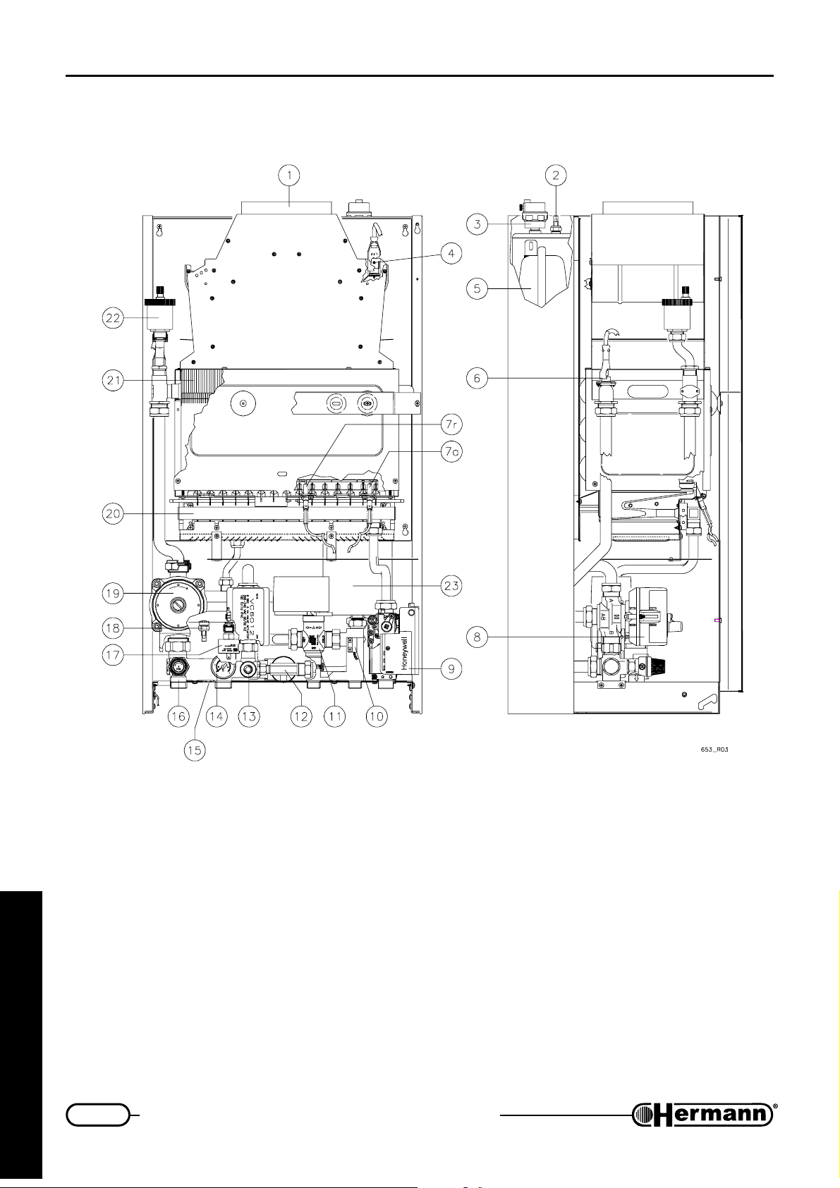
First firing, regulation and servicing instructions
Boiler internal components
EURA 23-28 E
1 Flue hood
2 Domestic minitank temperature sensor
3 Automatic air vent for sanitary minitank
for the technician
4 Flue thermostat
5 Expansion vessel
6 High temperature safety thermostat
7a Ignition electrode
7r Flame detection electrode
8 Motorised mixing valve
9 Gas valve
10 Priority flowstat
11 Motorised mixing valve
36
12 Automatic filling device
13 Drain valve
14 Manometer
15 By-pass
16 Safety valve 3 bar
17 Loss of water switch
18 Flow temperature sensor
19 Pump
20 Burner
21 Primary heat exchanger
22 Automatic air vent
23 Micro-storage
Page 37
First firing, regulation and servicing instructions
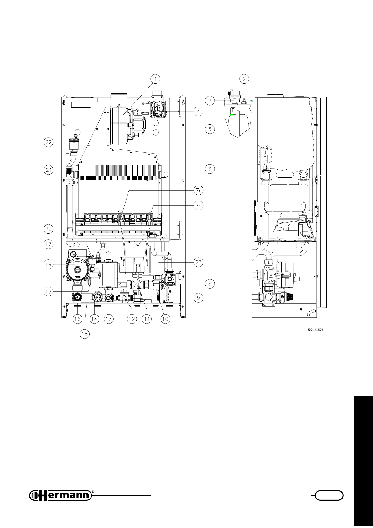
EURA 23 SE
1Fan
2 Domestic minitank temperature sensor
3 Automatic air vent for sanitary minitank
4 Flue pressurestat
5 Expansion vessel
6 High temperature safety thermostat
7a Ignition electrode
7r Flame detection electrode
8 Motorised mixing valve
9 Gas valve
10 Priority flowstat
11 Motorised mixing valve
12 Automatic filling device
13 Drain valve
14 Manometer
15 By-pass
16 Safety valve 3 bar
17 Loss of water switch
18 Flow temperature sensor
19 Pump
20 Sealed combustion chamber
21 Primary heat exchanger
22 Automatic air vent
23 Micro-storage
for the technician
37
Page 38
First firing, regulation and servicing instructions
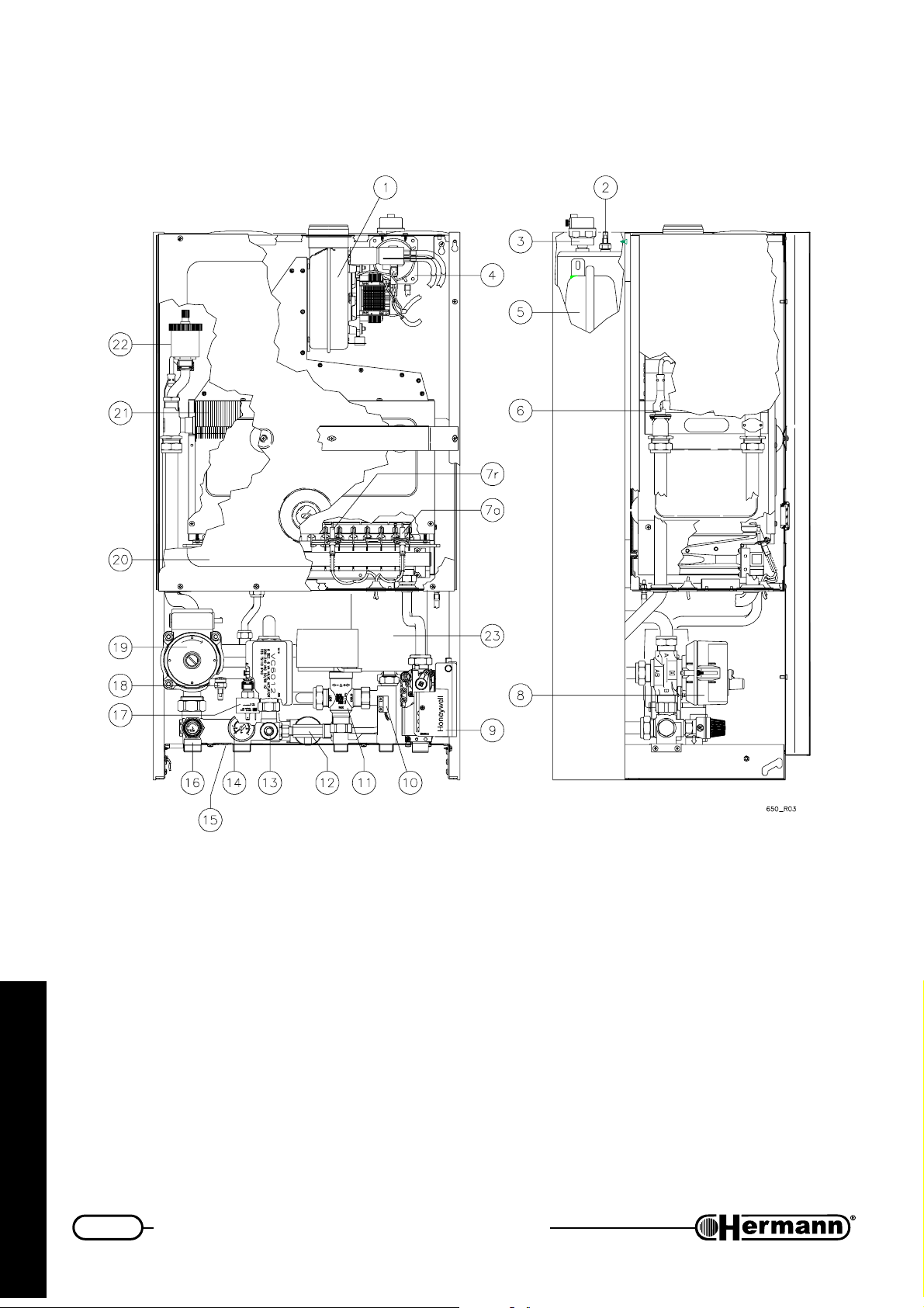
EURA 28-32 SE
1Fan
2 Domestic minitank temperature sensor
3 Automatic air vent for sanitary minitank
for the technician
4 Flue pressurestat
5 Expansion vessel
6 High temperature safety thermostat
7a Ignition electrode
7r Flame detection electrode
8 Motorised mixing valve
9 Gas valve
10 Priority flowstat
11 Motorised mixing valve
38
12 Automatic filling device
13 Drain valve
14 Manometer
15 By-pass
16 Safety valve 3 bar
17 Loss of water switch
18 Flow temperature sensor
19 Pump
20 Sealed combustion chamber
21 Primary heat exchanger
22 Automatic air vent
23 Micro-storage
Page 39
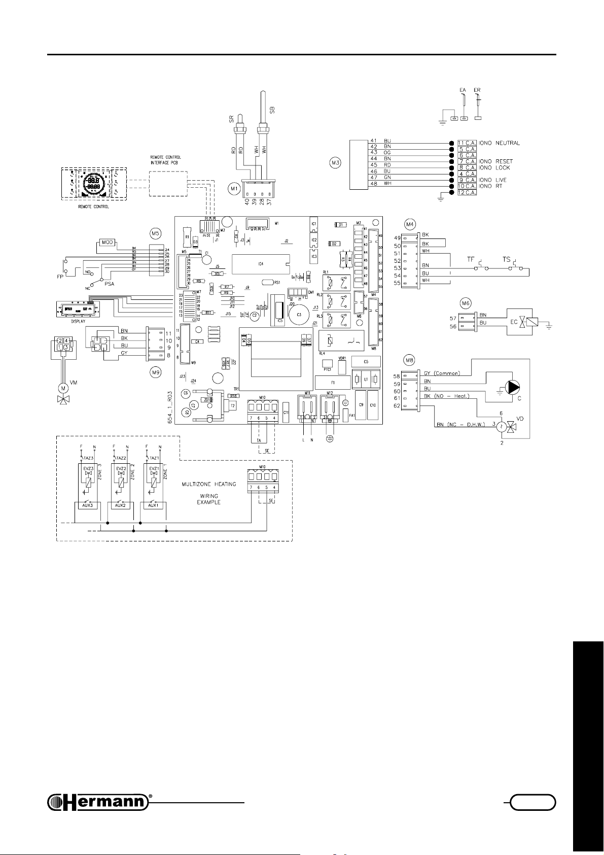
First firing, regulation and servicing instructions
Electrical diagram
EURA 23-28 E
C
C Pump
EA Ignition electrode
EC Automatic filling device
ER Flame detection electrode
FP Priority flowstat
L Electrical Phase
MOD Modulator
N Electric neutral
PSA Low water pressure switch
(contact “NO” closed = in
pressure)
SB Domestic minitank tempera-
ture sensor
SE External temperature probe
Note: if optional Remote Control is installed,
multizone heating wiring is different. Refer to
multizone heating diagram supplied with
Remote Control kit.
SR Flow temperature sensor
TA Room thermostat
TF Flue thermostat
TS High temperature safety
thermostat
VD Three way valve
VM Motorised mixing valve
EVZ 1/2/3 Electro-valve
zone 1/2/3
AUX 1/2/3 Auxiliary for
EVZ 1/2/3
TAZ 1/2/3 Room thermostat
for zone 1/2/3
Colours
abbreviations:
BK Black
BN Brown
BU Blue
GN Green
GNYE Green-Yellow
GY Grey
OG Orange
RD Red
VT Violet
WH White
for the technician
39
Page 40
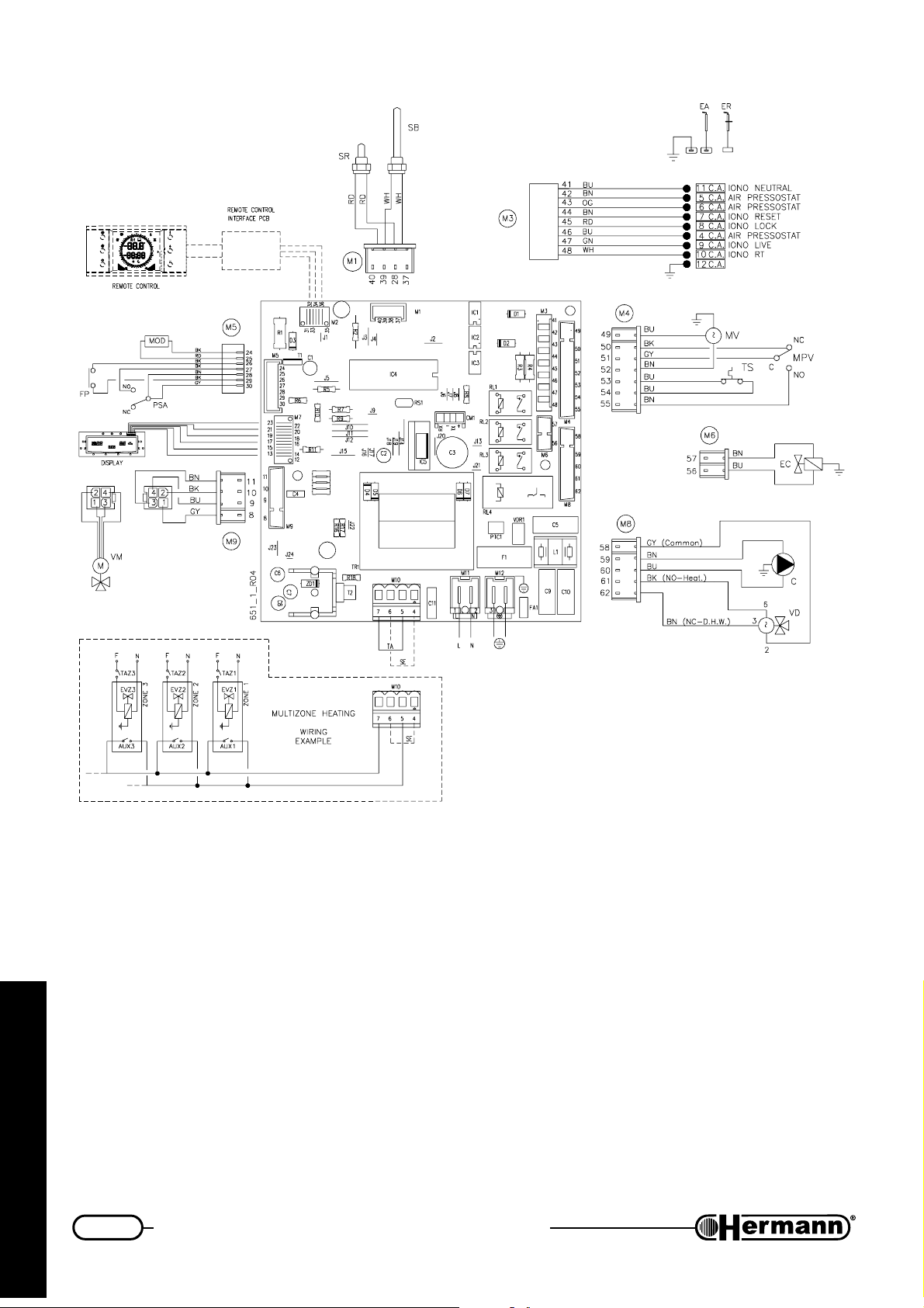
First firing, regulation and servicing instructions
EURA 23-28-32 SE
C
C Pump
EA Ignition electrode
EC Automatic filling device
ER Flame detection electrode
FP Priority flowstat
for the technician
L Electrical Phase
MOD Modulator
MPV Flue microswitch
MV Fan motor
N Electric neutral
PSA Low water pressure switch
(contact “NO” closed = in
pressure)
SB Domestic minitank tempera-
ture sensor
Note: if optional Remote Control is installed,
multizone heating wiring is different. Refer to
multizone heating diagram supplied with
Remote Control kit.
SE External temperature
probe
SR Flow temperature sensor
TA Room thermostat
TS High temperature safety
thermostat
VD Three way valve
VM Motorised mixing valve
EVZ 1/2/3 Electro-valve
zone 1/2/3
AUX 1/2/3 Auxiliary for
EVZ 1/2/3
TAZ 1/2/3 Room thermostat
for zone 1/2/3
Colours
abbreviations:
BK Black
BN Brown
BU Blue
GN Green
GNYE Green-Yellow
GY Grey
OG Orange
RD Red
VT Violet
WH White
40
Page 41
User instructions
USER INSTRUCTIONS
Warnings for boiler
commissioning
First ignition must be carried out by qualified technicians (in example HERMANN
Authorized Servicing Centres).
Gas conversion from a specific gas (natural gas or LPG) to another gas, can be made also when
the gas boiler is already installed, but only by a qualified technician. The technician will check that:
a) the label technical data of the gas boiler correspond to those of the gas, water and electrical
supply lines;
b) the main burner regulation is compatible with the gas boiler output;
c) the chimney works correctly, expelling the combustion products;
d) the air supply and the combustion products evacuation work correctly, in accordance with the
requirements in force;
e) the conditions for a correct ventilation are guaranteed, also when the gas boiler is located
inside a furniture.
for the user
Useful tips
WARNING for “E” models: The boiler is fitted with a safety thermostat for chimney
draught, operating in case of combustion products return in the installation room.
This device must be always in function, because a combustion products return can
cause chronic or acute intoxications with danger of death. If the thermostat must be
replaced, use the original spare part only. In case of repeated interventions of the
device, check that the Flue Products Outlet System is efficient and made according
to the laws in force (see examples in “Chimney connections”).
WARNING for “SE” models: The boiler is fitted with a safety flue pressure switch. This
device must be always in function. In case of repeated interventions, call a qualified
technician. If the pressure switch must be replaced, use the original spare part only. In
case of repeated interventions of the device, check that the Air Flue Products Inlet/
Outlet System is efficient and made according to the laws in force (see examples in
“Chimney connections” and “Flue options”).
INSTALLATION AND SERVICING
All installation, servicing and gas conversion operations MUST BE CARRIED OUT BY QUALIFIED
th
TECHNICIANS authorized by Law n. 46 dtd March 5
01 and 7131/99 requirements and revisions.
, 1990 and in accordance with UNI-CIG 7129/
Moreover, in accordance with art.11 section 4 of DPR 412/93 and revisions, boiler MAINTENANCE
operations must be made at least once a year and following manufacturer’s specifications and UNI
and CEI rules in force.
41
Page 42
User instructions
APPLIANCE BOOKLET OR CENTRAL PLANT BOOKLET
st
All appliances, even those installed before August 1
outputs less or equal 35 kW) or a central plant booklet (for outputs more than 35 kW). All ordinary
and special servicing operations and combustion checkings must be written on the booklet, together
with the name of the person responsible for servicing.
COMBUSTION CHECKING
Combustion checking is made with a control of the boiler efficiency; this checking must be carried
out only by a person with the requirements of the Law 46/90. Boilers that, after the checking, will
have efficiency rates lower than the ones required and not changeable with suitable adjustments,
must be replaced.
BOILER OPERATION AND SERVICING
The user (owner or tenant of the flat where the boiler is installed) or the administrator of the block of
for the user
flats (in case of a central heating system) are responsible for the appliance operation and servicing;
they can both transfer the responsibility of the servicing and eventually of the operation to another
person, which must have the requirements indicated by the Law 46/90. Even if the user or the
administrator decide to assume personally this responsibility, ordinary servicing of the warm air
heater and combustion checkings must be carried out by a qualified technician.
, 1994, must have an appliance booklet (for
Warnings
In case of gas smell:
a) do not press electrical switches, use the telephone or other objects that can provoke
sparks;
b) open immediately the windows and the doors in order to cleanse the room air;
c) close the gas supply taps;
d) call a qualified technician.
Do not obstruct the ventilation openings of the gas boiler room, in order to avoid
possible dangerous situations as the creation of poisonous or explosive mixtures.
Disconnect the gas boiler when it is not used for a long time; close then the gas tap
and turn off the double pole switch installed on the boiler power supply line.
Warning: if boiler is installed in a room where temperature can drop below 0°C, it is
recommended to fill the heating system with an anti freezing mixture.
Otherwise, In case of prolonged absence of the user, call the authorized servicing centre to
empty the system.
42
Page 43
User instructions
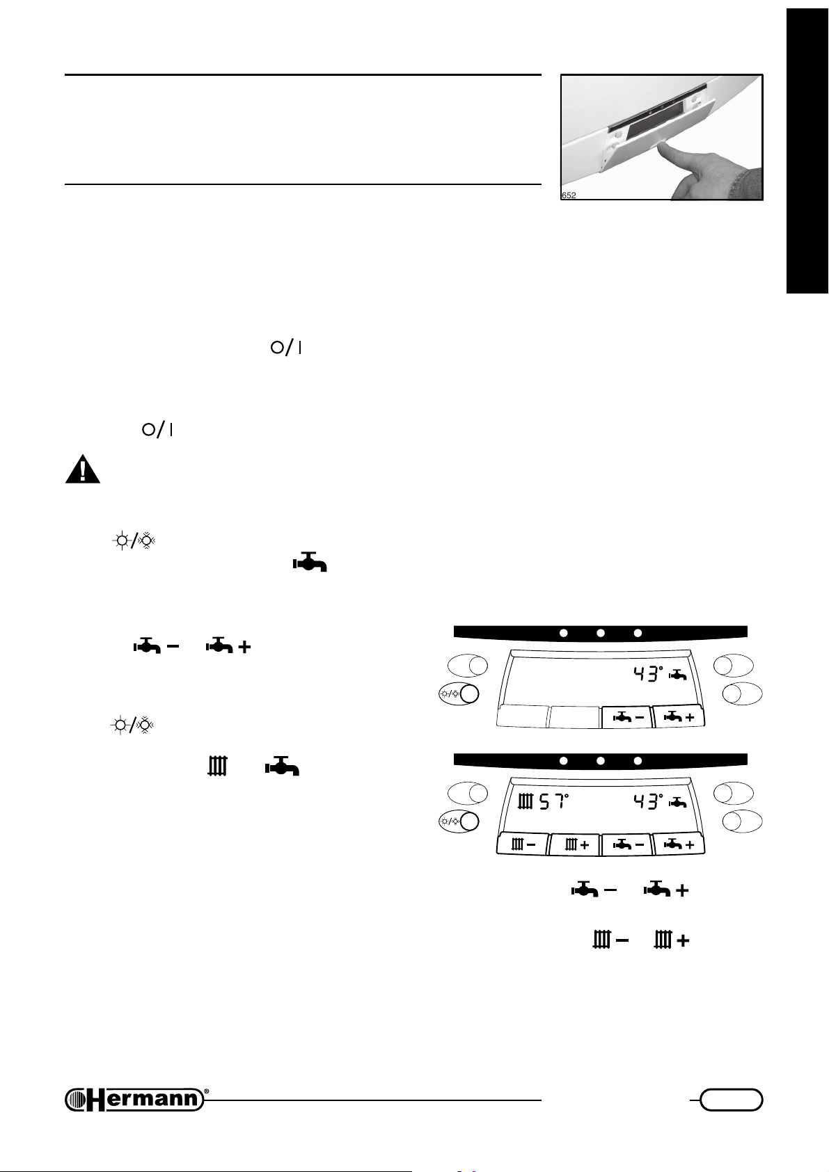
Gaining access to control panel
To gain access to control panel it is sufficient to softly push in the
lower part of control cover, as shown.
Switching on/off
and running boiler
SWITCHING ON
— Turn main electrical switch on; green light flashes
— Open gas tap and press
for working either in summer or in winter mode
SWITCHING OFF
— press
If boiler is unused for a long period of time it is recommended to close gas tap and
electrically disconnect boiler
“SUMMER” MODE
Press
on to display where the symbol appears together with set sanitary temperature (in °C).
Burner automatically switches on whenever there is a domestic hot water demand.
It is possible to change hot water temperature by
pressing
flashes for few seconds.
“WINTER” MODE
Press
WINTER mode is recognisable just looking on to
display where both and symbols appear
together with set sanitary and heating temperature (in °C).
: button: green light flashes
knob to work boiler in SUMMER mode. SUMMER mode is recognisable just looking
or : new set temperature
knob to work boiler in WINTER mode.
: button: green light is constantly on, indicating that boiler is ready
for the user
630C
Burner automatically switches on whenever there
is a request.
It is possible to change sanitary hot water temperature by pressing
temperature flashes for few seconds.
It is possible to change heating system water temperature by pressing
temperature flashes for few seconds. Afterwards actual (measured) temperature is shown.
Note: if you have a central heating lead by a third-parties room thermostat (or chrono thermostat),
it is adviced to set heating temperature to 65÷70°C
630D
or : new set
or : new set
43
Page 44
User instructions
If an external probe has been installed (optional Hermann kit), heating system temperature is
automatically controlled by boiler depending on external temperature. Pressing knobs
and
can vary a “dispersion coefficient” (please refer to technical documentation included with said kit).
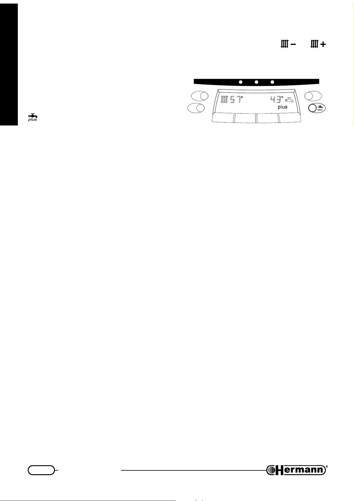
PLUS FUNCTION
Inserting PLUS function EURA produces hot water
in an extremely short time giving same comfort as
boiler with a big DHW tank.
To switch PLUS function on (off) it sufficient to press
knob, both in summer and winter mode. When
plus option is on, the writing ‘plus’ is displayed.
REGULATING ROOM TEMPERATURE
We want here to remind you that the room temperature must be regulated through a room
for the user
thermostat with two temperature levels. This required by law XXXX [Italian reference: DPR
26 Agosto 1993 n°412 and relevant changes].
Please always refer to instruction manual enclosed to room thermostat.
BOILER FILLING
630E
It is not necessary by end user to check water pressure inside boiler since EURA is provided with
a special automatic filling device.
In case of anomaly, a special alarm will be displayed. Please refer to paragraph ‘Boiler blocking and
alarm codes’.
ANTI FREEZING PROTECTION
Eura is equipped with an Anti freezing device, which keeps temperature in heating and domestic
system above 5 °C. Such system is enabled also when boiler is ‘OFF’ (green light flashing), provided
that boiler is fed by gas and electricity.
In case of gas or electricity failure, boiler can’t turn on and antifreeze protection is performed by
pump only, keeping water flowing.
It is important to underline that said anti freezing protection is a preventing device. It is not
recommendable to leave boiler unused for long periods where climate is very cold. In this cases
please contact a technical centre for either draining all system or inserting an anti freezing solution.
44
Page 45
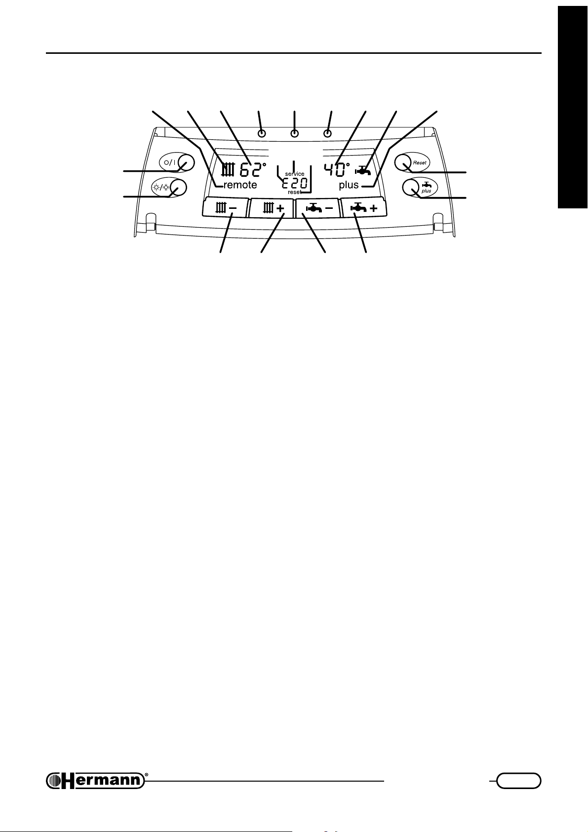
User instructions
Control panel details
17
16 15 14 13 12 11
19
18
20
10
1
2
630B
34
1 ON/STAND BY knob
• Pressing allows switching boiler on (on mode, green light on)
• Pressing once more boiler switches off (stand by mode, green light flashing), leaving anti
freezing protection on.
2 SUMMER/WINTER knob
• Pressing allows switching between summer and winter mode. For more details see
‘Switching on/off and running boiler’
56
9
8
7
for the user
3 HEATING SYSTEM TEMPERATURE (decrease) knob
4 HEATING SYSTEM TEMPERATURE (increase) knob
• Pressing these knobs allows a decrease/increase of 1°C in Heating flow water. Such
knobs work in winter mode only.
When you realize that room reaches too slowly desired temperature, increase this setting.
If room temperature goes over desired temperature, decrease this setting.
5 DOMESTIC SYSTEM TEMPERATURE (decrease) knob
6 DOMESTIC SYSTEM TEMPERATURE (increase) knob
• Pressing these knobs allows a decrease/increase of 1°C in domestic water.
7 PLUS knob
• Pressing this knob enable/disable “plus” function. For more details see “Switching on/off
and running boiler”.
45
Page 46

User instructions
8 RESET knob
• Before pressing this knob, please refer to “Boiler blocking and alarm codes” to understand
what happened and prevent future problems.
• Pressing this knob allows to reset boiler after a failure (that could be reset by end user);
when such type of failure occurs, warning writing ‘reset’ is displayed together with alarm
code (see 18 and 20 in enclosed picture), and RED light turns CONSTANTLY ON.
• If RED light FLASHES, and an alarm code and ‘service’ appears on to the display (18 and
19), it is necessary to call a technical centre to solve problem; reset knob is NOT working.
9 PLUS symbol
• When plus is displayed, “PLUS” function has been enabled.
10 HOT WATER symbol
for the user
• When hot water is ready at set temperature, this symbol is displayed, both in summer and
winter mode.
• When this symbol flashes, there is a hot water supply going on.
11 DOMESTIC SYSTEM TEMPERATURE displayed
• Set sanitary water temperature is shown. It flashes for few seconds while changing tem-
perature by pressing
12 Red light – BOILER BLOCKED
• When red light is off, boiler is normally working.
• When red light is CONSTANTLY on, a boiler failure, which can be reset by end user,
happened and ‘reset’ is displayed (18 and 20 in enclosed picture. Please refer to ‘Boiler
blocking and alarm codes’ to understand what happened and prevent future problems.
Then press ‘reset’ button.
• When red light FLASHES, and an alarm code and ‘service’ appears on to the display (18
and 19), it is necessary to call a technical centre to solve problem.
13 Orange light – BURNER WORKING
• When orange light is CONSTANTLY on, burner is ignited.
• When orange light FLASHES, it means that technical service stopped a particular function
of the boiler. After 20 minutes light will stop flashing and boiler will normally work.
or .
14 Green light – BOILER ON/STAND-BY
• When green light flashes, boiler is electrically fed, in stand-by mode.
• When green light is constantly on, boiler is ready to work.
46
Page 47
User instructions
15 HEATING SYSTEM TEMPERATURE displayed
• When indication is CONSTANTLY on, it shows heating system water ACTUAL temperatu-
re (flowing out the boiler).
• When temperature (or dispersion coefficient*) is modified pressing knobs
SET heating temperature (or dispersion coefficient*) FLASHES for few seconds.
* if optional external probe is installed.
16 HEATING symbol
• Boiler in winter mode
• While flashing, boiler is heating radiators.
17 REMOTE displayed
• Remote control has been installed; most of controls are now available on to remote control
only. Please refer to remote control instruction manual.
18 ALARM CODE displayed
• An alarm code is displayed after boiler blocking and identifies the type of failure occurred.
• Please refer to ‘Boiler blocking and alarm codes’ to understand what happened and prevent
future problems.
19 SERVICE displayed
• Boiler is blocked and can be reset by technical service only.
or ,
for the user
20 RESET displayed
• Boiler is blocked.
• Please refer to ‘Boiler blocking and alarm codes’ to: understand what happened; restore
boiler operation; prevent future problems.
Boiler blocking and alarm codes
In this section all alarm codes which can be displayed are described, together with the relevant
operations to be carried out by the USER to restore boiler operation.
If, carrying out the described operations, boiler does not work anyway, or blocking
happens again, please contact a Hermann Technical Centre.
All alarms displayed with red FLASHING light and ‘service’ writing on display MUST
be solved by a Hermann technical centre only. All technical description of causes and
solutions for ‘service’ alarms are described in “Crypt Warnings for Technical experts”.
07 Burner ON for combustion check
Cause: the burner was turned ON at maximum power for combustion check (this may be
caused by a wrong pressing of pushbuttons), and this is NOT a function useful for the
User.
Solution: Switch off boiler by pressing
boiler on again and use it normally.
E01 No flame
Red light: constantly on Alarm type: reset
, wait some seconds, and then you can turn the
47
Page 48

User instructions
Cause 1: Burner flame has not been successfully ignited or it has suddenly stopped.
Solution: Press ‘Reset’ button to re-ignite boiler.
If problem occurs again, check boiler and main gas tap, verifying gas network too.
Cause 2: Electrical connections are wrong.
Solution: Press ‘Reset’ button to re-ignite boiler.
If problem still exists, call a qualified technician to check Live, Neutral and Earth wirings, in
particular Live and Neutral must not be reversed. Otherwise, boiler can’t detect flame on
burner, and blocks.
The problem may be located in electrical distribution network too (unbalanced Neutral).
E02 Safety device interference
Red light: constantly on Alarm type: reset
for the user
Cause 1: Flue has not perfectly evacuated (maybe temporary, maybe on account of sudden
strong wind gust)
Solution: Press ‘Reset’ button to re-ignite boiler. If block insists:
• Check flue chimney
On “E” models:
• Check that the outlet which communicates with the outdoor, compulsory according to the
law, is not obstructed by pieces of furniture against the wall or by other objects. It is however
normal that the outlet is realized behind a radiator. The outlet must be of the dimension
prescribed by the law and must be cleaned inside: some types have an anti-insects net
which could have been dirtied by dust or by spider’s webs. Call a Qualified Technician
when it is necessary. [place here references to national laws or rules about openings requirements
(if any)]
• If in the room where the boiler is installed there are fireplaces, mantelpieces, stoves, coal
stoves or similar, fans for the Air Outlet, such as wall fans, aspiring cowls for cooking
boards with outlet pipe, let the technician check that the inlet is correctly OVERSIZED or
that there are the ADDITIONAL inlets as prescribed by the laws in force, because, otherwise,
these devices interfere with the evacuation of the Boiler’s Flue. [place here references to
national laws or rules about this matter]
On “SE” models:
• Check that the Inlet/Outlet Ducts, the respective terminals and the device for the checking
Cause 2: Boiler is overheated and safety thermostat forced boiler to block.
Solution: Wait 20/30 minutes to cool boiler down then press ‘reset’. If block happens again,
E05 Heating system flow temperature sensor damaged
Red light: flashing Alarm type: service
48
of the correct Flue Outlet (Flue Pressure Switch) are clean and in good condition. During
the Installation Process it is necessary to respect the prescriptions included in the national
and local regulations and laws, in addition to the slopes and measurement included in the
paragraphs “Chimney connections” and “Flue systems”.
please contact a [Hermann Technical Centre] [qualified technician].
Page 49

User instructions
Solution: call a [Hermann Technical Centre] [qualified technician].
E12 Domestic Mini tank sensor damaged
Red light: flashing Alarm type: service
Solution: call a [Hermann Technical Centre] [qualified technician].
E18 Boiler Filling in progress
Red light: off Alarm type: none
Cause: Heating system pressure dropped (most likely on account of a water leakage) and
boiler is automatically filled with water.
Solution: Wait until alarm code disappears.
If this operation occurs 3 times within 24 hours boiler will be blocked and ‘service’ will be
displayed because a big leakage is present in the heating system (radiators included).
Anyway, it is recommended to call a [Hermann Technical Centre] [qualified technician] in
case this operation is very usual.
Be careful that if boiler is filled with anti freezing solution, any automatic filling with water
will dilute solution.
E19 Filling not completed within available time
Red light: flashing Alarm type: service
for the user
Solution: call a [Hermann Technical Centre] [qualified technician].
E21 Low water pressure in the primary/heating system (3 automatic filling already
executed)
Red light: flashing Alarm type: service
Cause: There is a water leakage inside your heating system
Solution: Switch boiler off by pressing
Switch boiler on pressing again. E18 code may be displayed: it should disappear
within 5 minutes otherwise (if E21 code is on again) call a [Hermann Technical Centre]
[qualified technician]. Do not try to reset boiler once more.
E22 Imprecise data storing
Red light: flashing Alarm type: service
Solution: call a [Hermann Technical Centre] [qualified technician].
E29 modulation gas valve coil damaged (short circuit)
Red light: flashing Alarm type: service
Solution: call a [Hermann Technical Centre] [qualified technician].
E31 Remote control* not working
Red light: flashing Alarm type: service
and disconnect electrical line through main switch.
49
Page 50
User instructions
* This applies to Hermann Remote Control optional kit only, and not to third parties chrono
thermostats.
Solution: call a [Hermann Technical Centre] [qualified technician].
In these conditions, boiler can only produce domestic hot water. If necessary, ask the
technician to make the boiler provisionally work in manual heating: information for this
operation are in “Crypt Warnings for Technical experts” paragraph (refer to alarm code
E31).
Eventual problems
BURNER DOES NOT IGNITE
— Verify if green light is constantly on:
for the user
• If green light is off boiler is not electrically connected;
• If green light flashes boiler is off. Press
— Verify if red light is constantly on. In this case boiler is blocked: please refer to ‘Boiler blocking
and alarm codes’;
— After switching boiler on by pressing
During this period of time boiler does not work;
— If a room thermostat is installed, please check if it is regulated at a temperature higher then
room temperature and that boiler is in Winter mode (both symbols
displayed).
LOW DOMESTIC HOT WATER PRODUCTION
— Check if domestic hot water temperature is enough high; in case increase temperature by
pressing
— Call a technical service centre to verify gas valve;
— Call a technical service centre to verify domestic heat exchanger.
In case of particular water hardness, a water softener must be installed.
;
or after a reset it is necessary to wait 90 seconds.
to switch it on.
and must be
Do not try to repair boiler by yourself.
For any problem related to electric circuit, hydraulic circuit, gas circuit, a Hermann technical
centre must be contacted.
All boilers must be equipped with original spare parts.
Hermann cannot be considered liable for eventual damages caused by improper, wrong,
irrational use of material not original.
50
Page 51
User instructions
Warning while using
— Check frequently water pressure on the hydrometer and verify that, when the system is cold,
water pressure values are in line with the manufacturer instructions.
Do not touch the heated surfaces of the boiler, as the doors, the flue, the chimney
pipe, etc., also after the boiler operation because, for a certain time, these surfaces
are oveheated. Any contact with them can cause dangerous scalds. It is then forbidden
to let children or inexperienced people be close to the boiler, during its operation.
— Do not expose the wall hung gas boiler to water vapours directly coming from gas cookers/
hobs.
— Do not wet the gas boiler with water or other liquids sprinklings.
— Do not put any object on the gas boiler.
— The gas boiler utilization is forbidden to children and to inexperienced people.
— If the gas boiler is going to be definitively unused, call a qualified technician to carry out all
required operations, checking in particular disconnection of gas, water and electrical supplies.
— On EURA E models only: The installation of aspirators, fireplaces or similar appliances in the
boiler room (and in adjacent rooms in case of indirect ventilation), must be made in compliance
with all specific safety rules and laws (for example by augmenting the dimensions of ventilation
openings), even in case of modifications or additions.
for the user
INSTRUCTIONS MANUAL
Make sure that the present manual is ALWAYS with the boiler, for any consultation of the user and
servicing personnel.
HERMANN CONVENTIONAL GUARANTEE CONDITIONS
Hermann offers to the customer a particular and exclusive CONVENTIONAL GUARANTEE, which
is automatically activated asking the First Ignition to a Hermann Authorized Service Center. The
conditions of the HERMANN CONVENTIONAL GUARANTEE don’t prejudge nor invalidate the
rights indicated by the European Rule 1999/44/CE actuated with Italian Laws by the Decree 02
Februar 2002 N°24 of which the User is the Owner.
51
Page 52

GAS BOILERS
HERMANN S.r.l. Via Salvo d’Acquisto
29010 Pontenure (PIACENZA) ITALY - Tel. +39.0523.510341
E-MAIL: [email protected]
notice; therefore, this manual cannot be considered as a contract towards third parties.
In order to constantly improve its products, Hermann Ltd. has the right to change features and data written in the present manual, at any time and without
Hermann Ltd. declines any responsibility for eventual printing and/or transcription errors in the present manual.
www.hermann.it
10/2005 COD. 982.180002 / REV. 017
(UKENG)
 Loading...