

HermanMiller renew Installation Manual
HermanMiller
Renew
Base product number (DU)
™
Table Installation
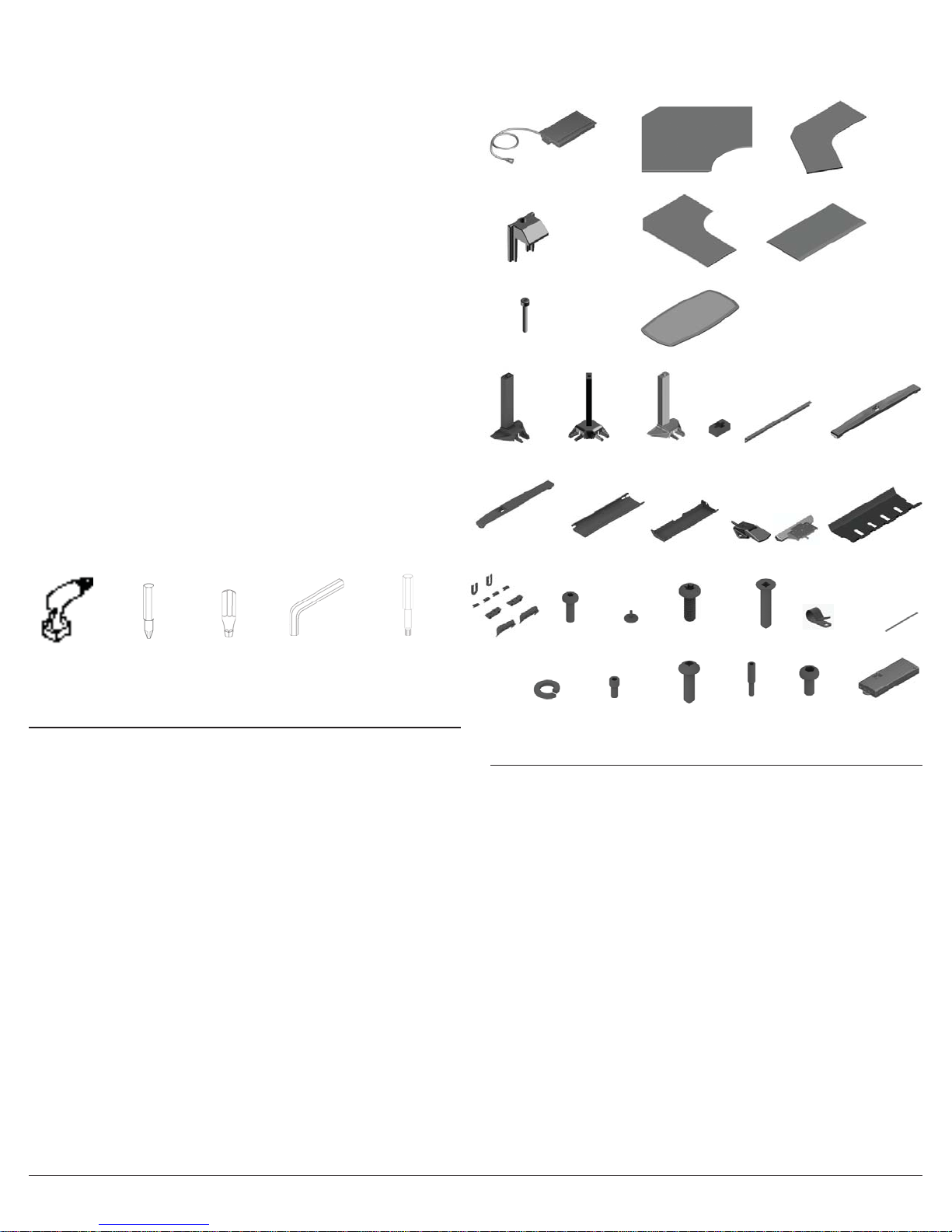
Parts Included
Y
How to assemble
your table
Illustrations and speci cations are based on the latest product information available at the time of publication.
The right is reserved to make changes in design and speci cations at any time, without notice, and also to discontinue
products.
For more information about our products and services or to see a list of dealers,
For assistance: Please visit us at www.hermanmiller.com/product-instructions or call 888-443-4357
© 2015 Herman Miller, Inc., Zeeland, Michigan Printed in U.S.A. Part No. 1bc4vh - E.
TM
Renew is among the trademarks of Herman Miller, Inc.
Notice:
Some of the parts have been wrapped to protect them during shipping. Remove the plastic
wrap before assembling the table.
Assemble products on a protective surface.
Tools Required
Philips-Recess Bit
Power Driver
Use extension bit if required, Magnetic bits are recommended.
Not all tools are used on all tables.
Size: #2
Square-Recess Bit
Size: #2
IMPORTANT SAFETY INSTRUCTIONS
Hex/Allen
Wrench Size:
5mm and
8mm
Torx Bit
Size: T30
Logic Unit
AD
AE Clamp
AF Screw
LegB
C Leg Foot
G
M
Hardware Kit
T
Note: Not all the parts shown above are applicable for all the tables.
C
Machine
N
Screw
Lock Washer
Extended
Corner Leg
H
Wire Cover
V
90° Work Surface 120° Work Surface
Extended Corner Work Surface
Oval Work Surface
Leg with
AA
Hidden Power
Assembly
Cable Collector
J
Tapping Hex
Glide
PR
Socket
Head Screw
Tapping Screw
WXY
Peg
D
Foot
S
Rectangular Work Surface
A
Support Rail
E
Switch
K
Tapping Screw
Fastener
Work Surface Options
F
T Leg Foot
Retainer Kit
L
Separates user power
cables from table
power cables
Cable Clamp
AB
Button Head
Screw
Z
AC
Control Box
Velcro
When using an electrical furnishing, basic precautions should always be followed, including
the following:
Read all instructions before using this furnishing.
DANGER - To reduce the risk of electric shock always unplug this furnishing from the
electrical outlet before cleaning.
WARNING - To reduce the risk of burns, re, electric shock, or injury to persons:
Close supervision is necessary when this furnishing is used by, or near children, invalids, or
disabled persons.
Sitting or standing on product may cause risk of personal injury (use for chairs, tables
consider obvious misuse of product).
Use this furnishing only for its intended use as described in these instructions. Do not use
attachments not recommended by the manufacturer.
Never operate this furnishing if it has a damaged cord or plug, if it is not working properly, if
it has been dropped or damaged, or dropped into water. Return the furnishing to a service
center for examination and repair.
SAVE THESE INSTRUCTIONS
HermanMiller RenewTM Table (Height Adjustable - Electrical) Assembly Instructions1
Failure to fully tighten screws (bolts) may cause injury by causing Renew tables to collapse.
Tighten screws (bolts) until they stop plus a quarter turn.
Periodically check to make sure legs are properly aligned. Failure to do so may cause risk of
personal injury.
If using power drive set on low torque.
Keep the cord away from heated surfaces.
Never drop or insert any object into any opening.
Do not use outdoors.
Do not operate where aerosol (spray) products are being used or where oxygen is being
administered.
This furnishing is intended for commercial use
control box rating: 4.8A, 120V
Max FPDU rating: 15A, 120V
Duty cycle: 1min on, 18min o
Part no. 1bc4vh rev F
WARNING - Risk of Electric Shock – Connect this furnishing to a properly grounded outlet
only. See Grounding Instructions.
For loading always put heavier items in the center and distribute the load.
Maximum load rating is 120 lbs.
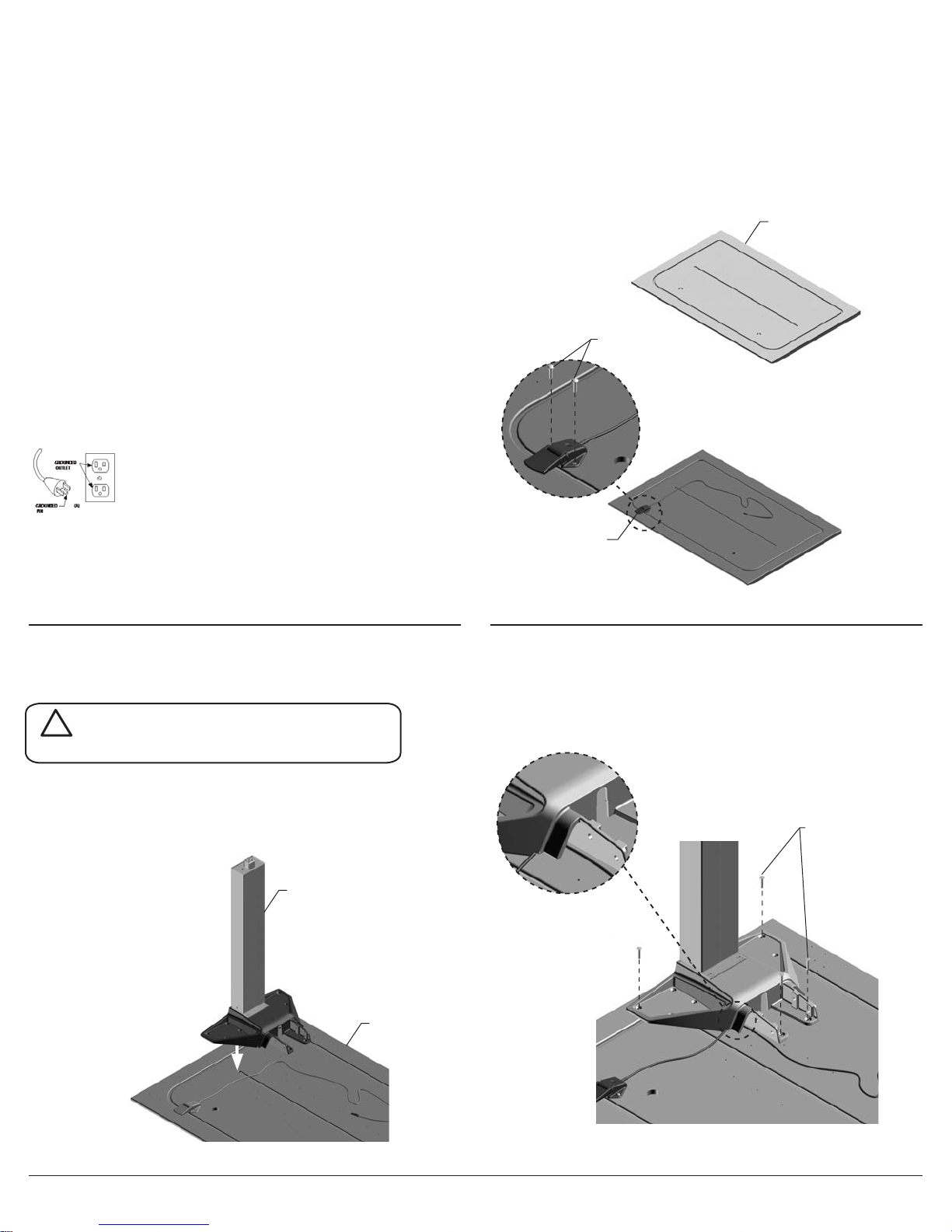
GROUNDING INSTRUCTIONS
This product must be grounded. If it should malfunction or breakdown, grounding provides a
path of least resistance for electric current to reduce the risk of electric shock. This product is
equipped with a cord having an equipment-grounding conductor and a grounding plug. The
plug must be plugged into an appropriate outlet that is properly installed and grounded in
accordance with all local codes and ordinances.
DANGER – Improper connection of the equipment-grounding conductor can result in a risk
of electric shock. Check with a quali ed electrician or serviceman if you are in doubt as to
whether the product is properly grounded. Do not modify the plug provided with the product.
if it will not t the outlet, have a proper outlet installed by a quali ed electrician.
This product is for use on a nominal 120-volt circuit and has a grounding plug that looks like
the plug illustrated in Sketch A. Make sure that the product is connected to an outlet having
the same con guration as the plug. No adapter should be used with this product.
Step 1
Switch Installation
1.1 Lay the Surface (A) upside down.
1.2 Pick the sides on the surface top where the power switch needs to be installed. Holes are
pre-drilled on either side of the work surface. Install switch using Tapping Screws (Y).
A
W
Step 2
T & C Leg Installation (T & C options)
!
WARNING -RISK OF TABLE TIPPING-
Make sure C legs are placed in correct location.
2.1 For C-leg nd the qty(4) pre-drilled holes located on more towards back of the work surface.
For T-leg use the center pre-drilled holes.
2.2 Ensure switch cable is properly positioned under top casting.
B
K
2.3 Install the Tapping Screws (S) to the pre-drilled holes in leg in the order as shown in gure
below.
S
A
HermanMiller RenewTM Table (Height Adjustable - Electrical) Assembly Instructions2
Part no. 1bc4vh rev E.

2.4 Install the remaining Tapping Screws (S) onto leg which is not pre-drilled. Do the same for
other side.
S
Step 3
Extended Corner Leg Installation
3.1 Align the holes on the Extended Corner Leg Top (C) Casting with the holes of work surface (A).
Install Tapping Screws (S) using power driver.
3.2 Install Peg foot (D) to the leg and tighten the Fastener (X) and Socket (V) using allen wrench.
3.3 Install Glide (P) into Fastener (X).
X
V
B
A
D
C
Step 4
Support Rail Installation
4.1 Attach the Support Rail (E) with Button Head Screws (Y) and Washers (T) to casting
(User/Front edge side) and screw it down to the Work Surface (A) with Tapping Screws (W).
4.2 Switch cable should go through rail cable tie hole as shown.
S
P
X
YT
Rear edge side
W
HermanMiller RenewTM Table (Height Adjustable - Electrical) Assembly Instructions3
User/Front
edge side
E
Part no. 1bc4vh rev E.
 Loading...