

Page 1
TM
Locale
L-Desk and T-Desk Installation
Y
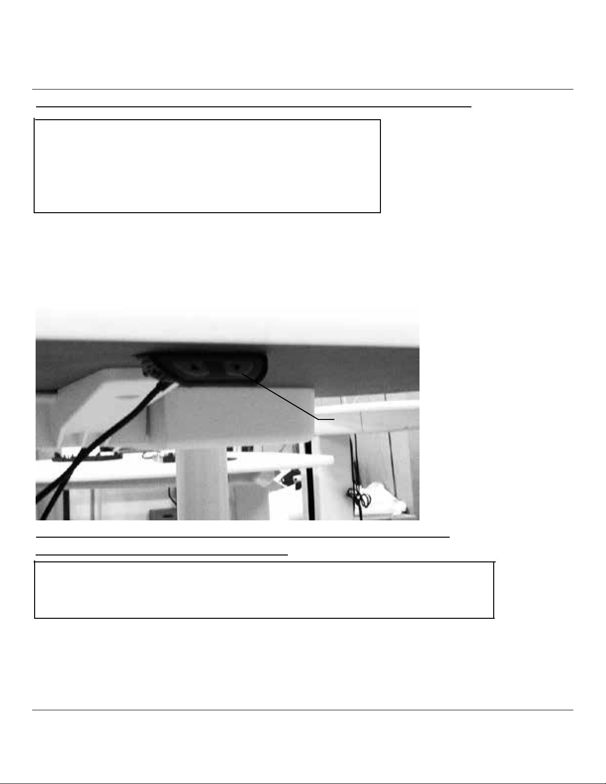
LOCALE HEIGHT ADJUSTABLE DESK OPERATING INSTRUCTIONS
CAUTION: WHEN OPERATING THIS DESK,
MAKE SURE TO REMOVE ANY OBJECTS OR
OBSTRUCTIONS THAT COULD BE IN THE WAY OF
THE MOVING DESK TOP. The rated load For the desk
is 200 lbs. maximum.
1) To operate the height adjustable desk, press the up or
down arrows on the control switch located under the
front edge of the desk top.
2) Press the up arrow to move the desk top higher.
3) Press the down arrow to move the desk top lower.
Control Switch
PARAMÈTRES RÉGIONAUX RÉGLABLE EN HAUTEUR BUREAU
INSTRUCTION DE FONCTIONNEMENT
ATTENTION : LORS DE L’UTILISATION DE CE BUREAU, ASSUREZ-VOUS DE RETIRER
TOUT OBJESCTS OU OBSTRUCTIONS QUI POURRAIENT ÊTRE DANS LA FACON DE LE
DEPLACER DESSUS DE BUREAU. LA CHARGE NOMINAL POUR LE BUREAU EST DE
90.7 KG MAXIMUM.
1) Pour faire fonctionner la hauteur réglable de bureau, appuyez sur les èches
vers le haut ou le bassur le commutateur de commande situé sous le bord du
bureau.
2) Appuyez sur la èche vers le haut pour déplacer le desk top supérieur.
3) Appuyez sur la èche vers le bas pour déplacer le bureau inférieur le plus
haut.
Z
© 2017 Herman Miller, Inc. Zeeland, Michigan. Printed in the U.S.A.
TM
Sense, Setu, Tu, Traverse and Locale are among the trademarks of Herman Miller, Inc.
Illustrations and specifications are based on the latest product information available at the time of publication.
The right is reserved to make changes in design and specifications at any time, without notice, and also to discontinue products.
Part no. 1bch5g rev D.
1
Page 2
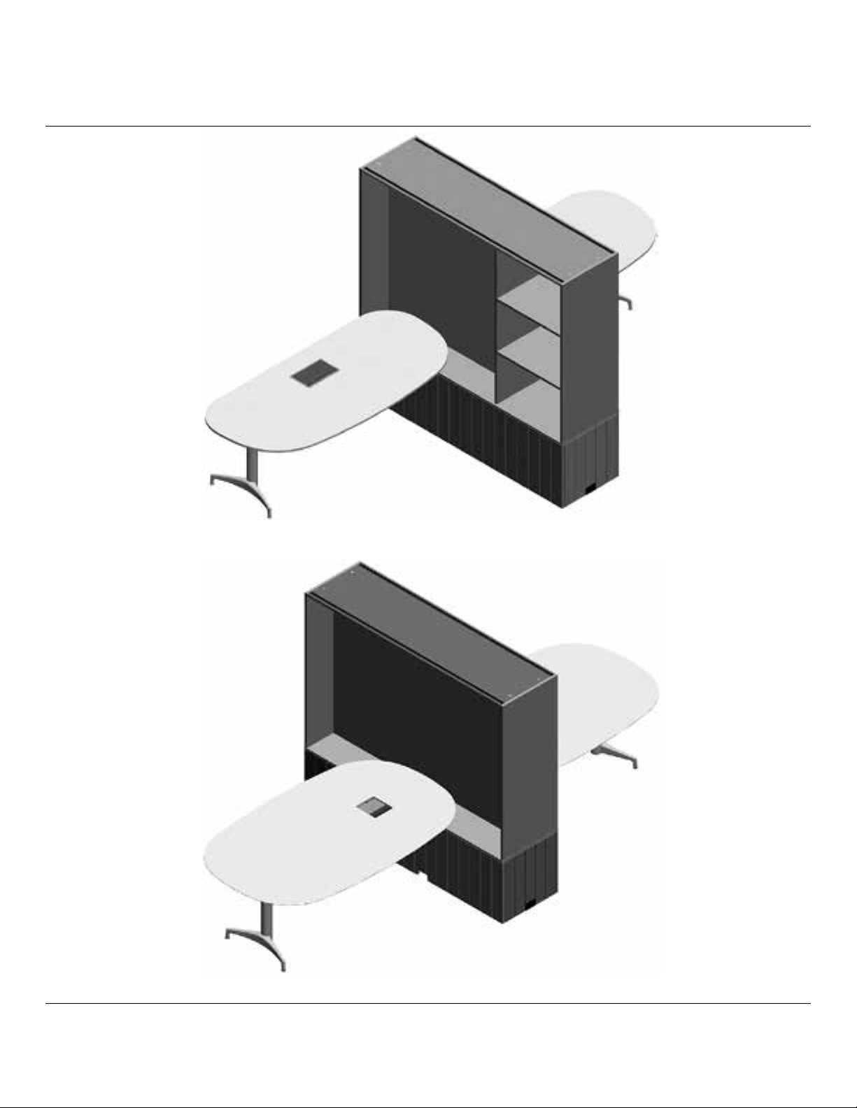
L-Desk
(Shown throughout instructions)
Z
© 2017 Herman Miller, Inc. Zeeland, Michigan. Printed in the U.S.A.
TM
Sense, Setu, Tu, Traverse and Locale are among the trademarks of Herman Miller, Inc.
Illustrations and specifications are based on the latest product information available at the time of publication.
The right is reserved to make changes in design and specifications at any time, without notice, and also to discontinue products.
T-Desk
Part no. 1bch5g rev D.
2
Page 3
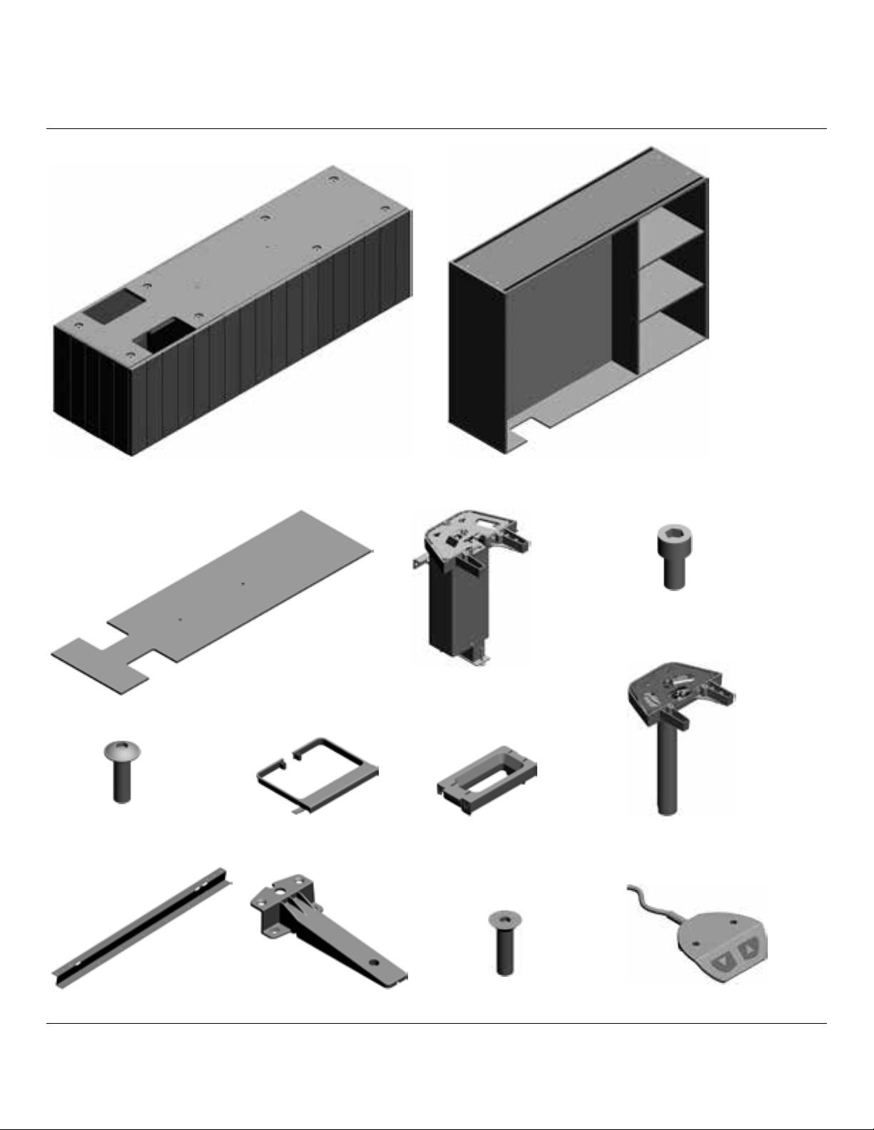
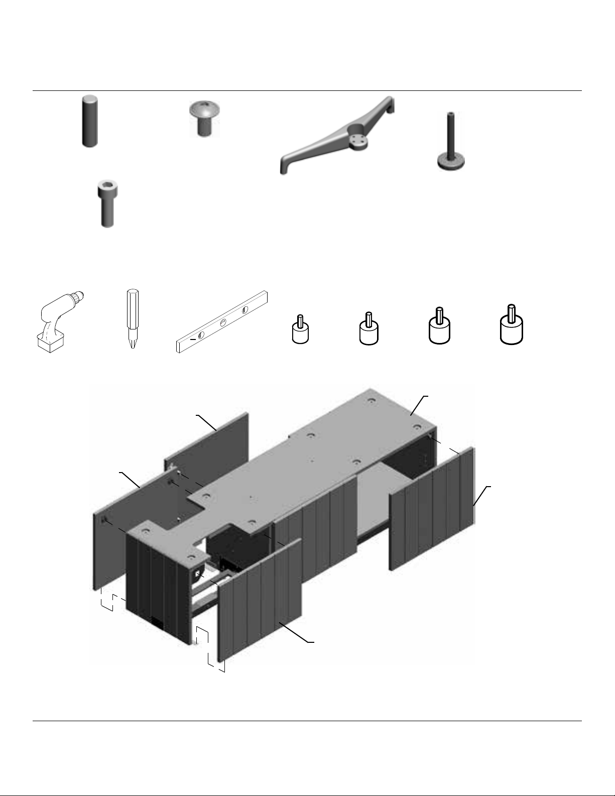
Parts Included:
A
Base Assembly
B
Upper Case
Base Top
C
M6 x 20 Socket
Flange Head Screw(8)
F
Rail
K
Column Shroud
G
Work Surface
Support
L
Z
© 2017 Herman Miller, Inc. Zeeland, Michigan. Printed in the U.S.A.
TM
Sense, Setu, Tu, Traverse and Locale are among the trademarks of Herman Miller, Inc.
Illustrations and specifications are based on the latest product information available at the time of publication.
The right is reserved to make changes in design and specifications at any time, without notice, and also to discontinue products.
D
M
Column
Wire Guide
H
M8 x 30 Socket Flat Head
Machine Screw(12)
M8 x 16 Hex Socket
Head Machine
E
Screw (4)
End Column
J
N
Control Switch
Part no. 1bch5g rev D.
3
Page 4
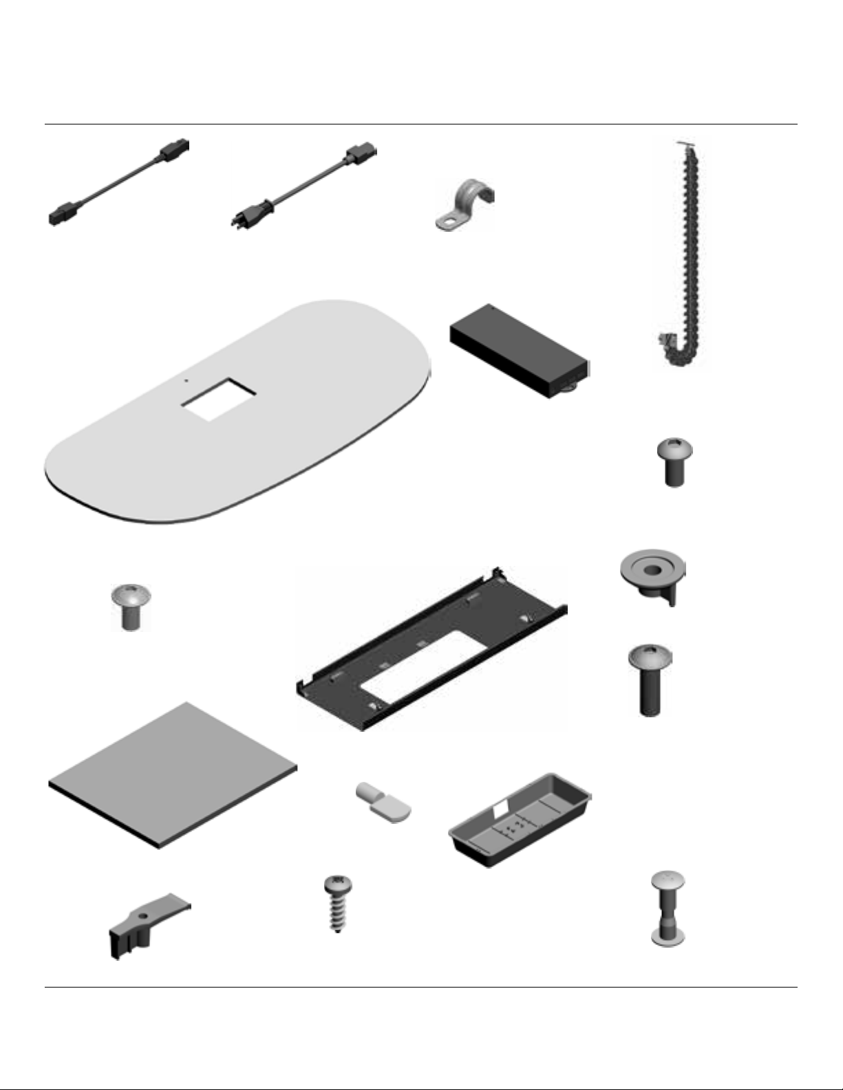
Motor Cable Power Cable
P R
Work Surface
V
M5 x 12 Socket Button
Flange Head Machine
Z
Screw(22)
T
Cable Clamp
Control Box
W
Service Chain
U
M5 x 12 Socket Button
Head Cap Screw(4)
X
Y
Mushroom Fastener(6)
AA
AD
AC
AE
Z
© 2017 Herman Miller, Inc. Zeeland, Michigan. Printed in the U.S.A.
TM
Sense, Setu, Tu, Traverse and Locale are among the trademarks of Herman Miller, Inc.
Illustrations and specifications are based on the latest product information available at the time of publication.
The right is reserved to make changes in design and specifications at any time, without notice, and also to discontinue products.
Grommet Clamp(2)
Shelf(2)
AF
M3.5 x 12 Plastite
Pozi Pan Head
Screw
Shelf Pins(8)
Cable Tray
AB
AJ
Wire Tray
M5 x 16 Socket Button
Head Flange Screw(6)
AG
Clamping Screw
Part no. 1bch5g rev D.
4
Page 5
AH
Dowel Pin
AK
M5 x 10 Flange Head
Screw(3)
M8 x 25 Hex Socket
AN
Head Machine
Screw (4)
Tools Needed:
Power Driver
Access Panel
#2 Phillips Bit
Door
Level
AL
3mm Metric
Hex Bit
Column Leg
4mm Metric
Hex Bit
AM
5mm Metric
Hex Bit
A
Leg Glide
6mm Metric
Hex Bit
Door
Access Panel
1. Place Base at desired location.
2. Open or remove Doors.
3. Remove Access Panels by pulling out at top of panel, then lifting up and out.
Z
© 2017 Herman Miller, Inc. Zeeland, Michigan. Printed in the U.S.A.
TM
Sense, Setu, Tu, Traverse and Locale are among the trademarks of Herman Miller, Inc.
Illustrations and specifications are based on the latest product information available at the time of publication.
The right is reserved to make changes in design and specifications at any time, without notice, and also to discontinue products.
Part no. 1bch5g rev D.
5
Page 6
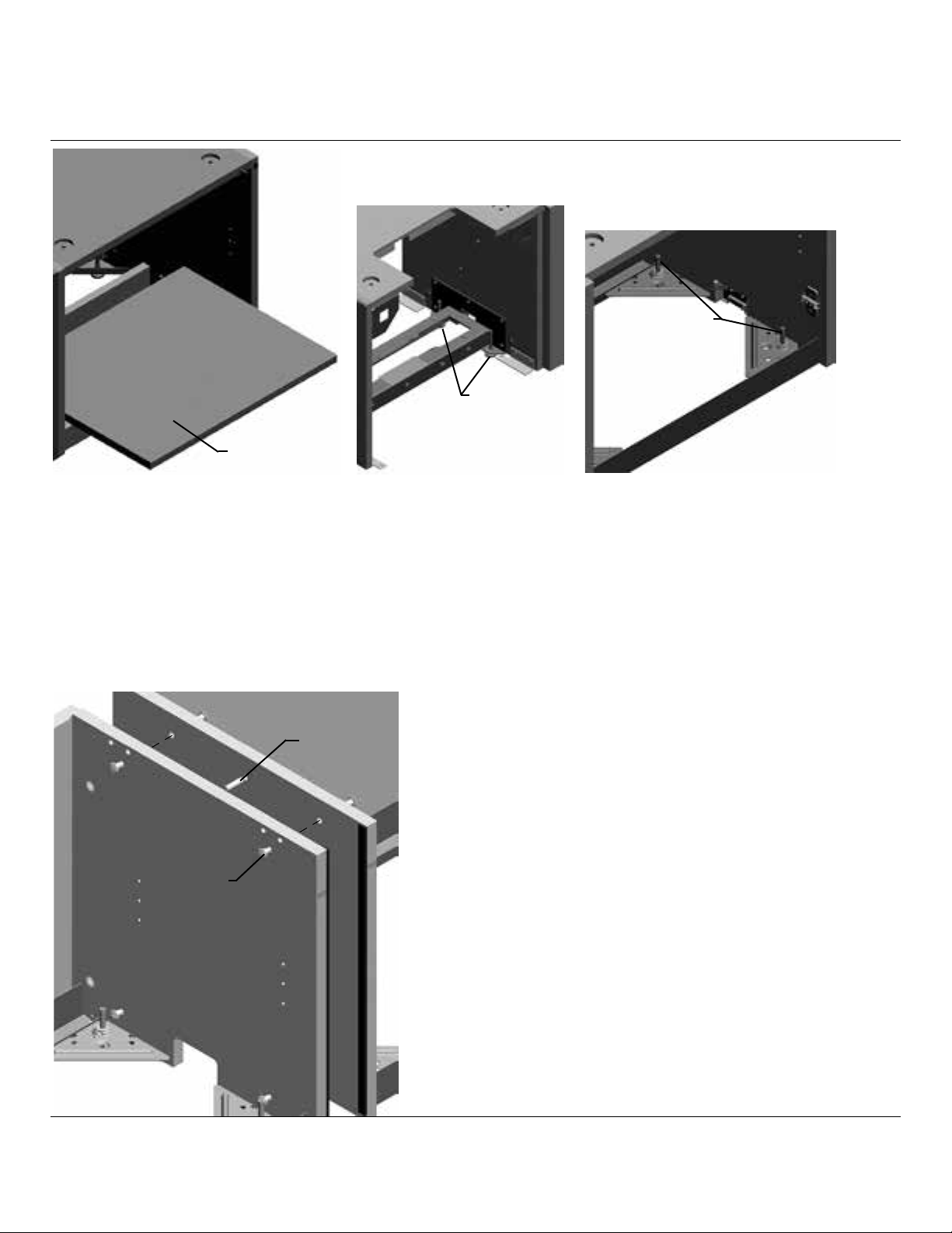
Outside Glide
Inside Glide
Bottom Shelf
4. Remove Bottom Shelves from Base.
5. Level base by adjusting Outside Glides rst. Then adjust Inside Glides down
to touch oor.
(Note: View shown with top panel
removed for clarity.)
D
C
Z
© 2017 Herman Miller, Inc. Zeeland, Michigan. Printed in the U.S.A.
TM
Sense, Setu, Tu, Traverse and Locale are among the trademarks of Herman Miller, Inc.
Illustrations and specifications are based on the latest product information available at the time of publication.
The right is reserved to make changes in design and specifications at any time, without notice, and also to discontinue products.
6. If More than one unit are to be
installeded in a run; position adjoining
unit next to one already in position.
7. Level and align that unit to mate with
other.
8. Connect bases with 4 Clamping
Screws (C) and 1 Dowel Pin (D).
Part no. 1bch5g rev D.
6
Page 7
Access Cover
9. Remove Access Covers from Base End Panels.
10. Install Electrical Harnesses to Base.
Break Out
11. Break out opening in Access Covers if required.
12. Return Access covers to Base.
Z
© 2017 Herman Miller, Inc. Zeeland, Michigan. Printed in the U.S.A.
TM
Sense, Setu, Tu, Traverse and Locale are among the trademarks of Herman Miller, Inc.
Illustrations and specifications are based on the latest product information available at the time of publication.
The right is reserved to make changes in design and specifications at any time, without notice, and also to discontinue products.
Part no. 1bch5g rev D.
7
Page 8
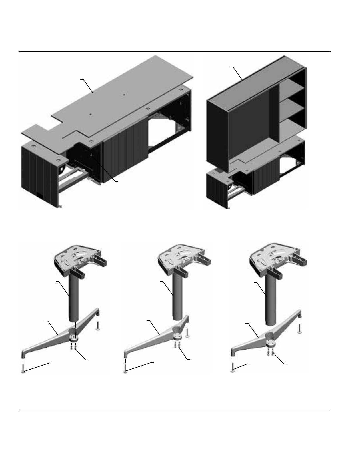
B
C
F
13. Position Base Top (C) or Upper Case(B) onto Base. Secure to Base with 8
Pan Head Machine Screws (F).
J J
AL
AM
T-Desk
14. Turn Glides (AM) into Column Leg (AL).
15. Attach Column Leg to End Column (J) with 4 Hex Socket Head Machine
Screws (AN) with the torque 130 inch lbs or 15 Nm force.
Z
© 2017 Herman Miller, Inc. Zeeland, Michigan. Printed in the U.S.A.
TM
Sense, Setu, Tu, Traverse and Locale are among the trademarks of Herman Miller, Inc.
Illustrations and specifications are based on the latest product information available at the time of publication.
The right is reserved to make changes in design and specifications at any time, without notice, and also to discontinue products.
AN
AL
AM
L-Desk, RH
AN
J
AL
AM
L-Desk, LH
AN
Part no. 1bch5g rev D.
8
Page 9
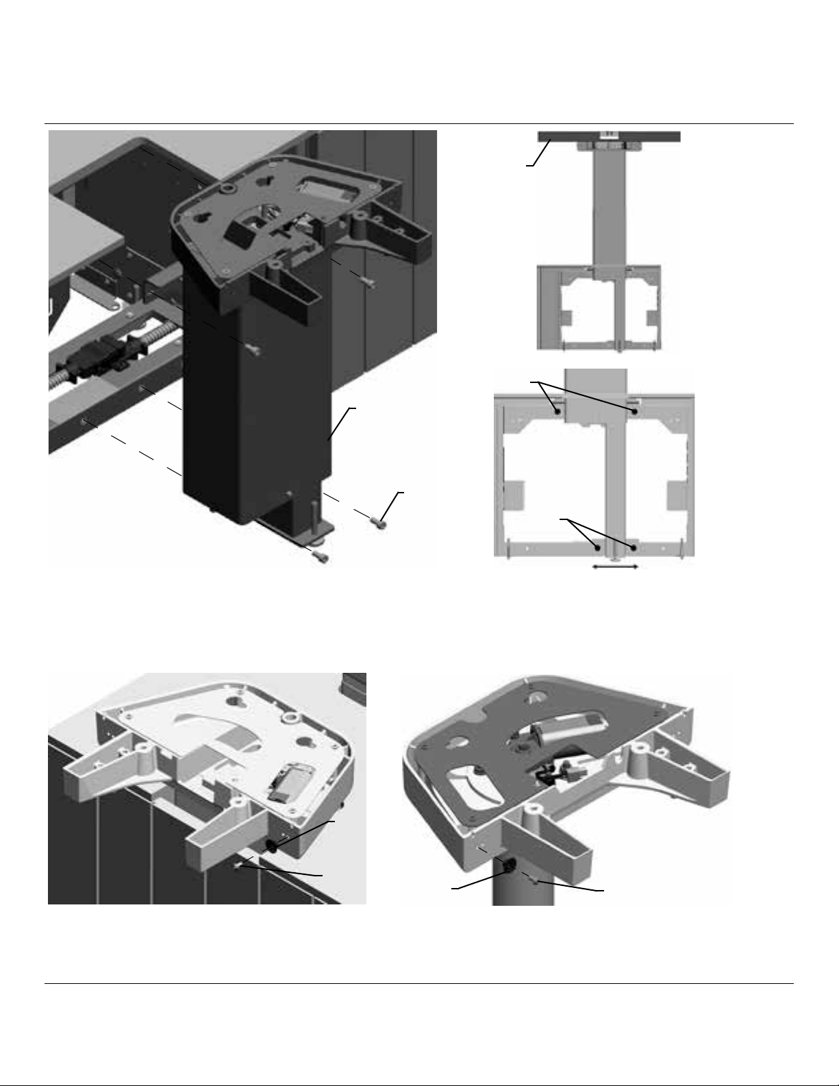
D
Level
Top Screws
E
Bottom
Screws
16. Assemble Column(s) (D) to Base with 4 Socket Head Machine Screws (E).
17. Fully Tighten Top Screws. Loosely tighten Bottom Screws.
18. Move lower end end of column until Level on top casting shows true.
19. Fully tighten Bottom Screws.
Y
AJ
Y
20. Determine which side of Work Surface Wire Cover will be accessed from.
Attach Mushroom Fastener (Y) to Column and End Column with Flange
Screws (AJ) where cover will latch. Image shows correct position for T-Desk.
AJ
Z
© 2017 Herman Miller, Inc. Zeeland, Michigan. Printed in the U.S.A.
TM
Sense, Setu, Tu, Traverse and Locale are among the trademarks of Herman Miller, Inc.
Illustrations and specifications are based on the latest product information available at the time of publication.
The right is reserved to make changes in design and specifications at any time, without notice, and also to discontinue products.
Part no. 1bch5g rev D.
9
Page 10
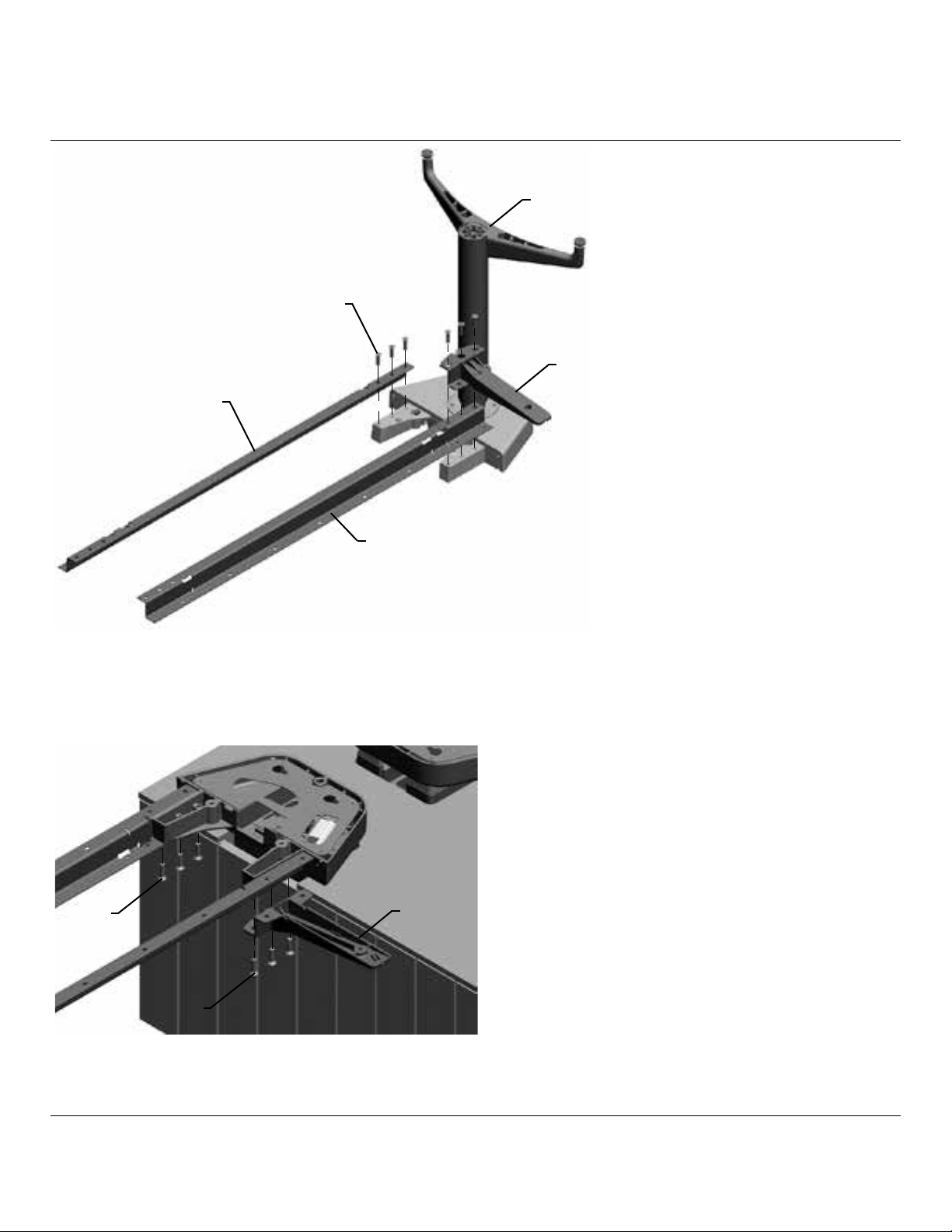
J
M
L
K
K
21. Place End Column (J) bottom side up.
22. Set Rails (K) onto Column (J).
23. Position Work Surface Support (L) onto Rail.
24. Secure all together with 6 Flat Head Machine Screws (M).
M
L
M
25. Place the assembly onto the Column.
26. Position the other Work Surface Support (K) onto Rail.
27. Secure all in place with 6 Flat Head Machine Screws (L).
Z
© 2017 Herman Miller, Inc. Zeeland, Michigan. Printed in the U.S.A.
TM
Sense, Setu, Tu, Traverse and Locale are among the trademarks of Herman Miller, Inc.
Illustrations and specifications are based on the latest product information available at the time of publication.
The right is reserved to make changes in design and specifications at any time, without notice, and also to discontinue products.
Part no. 1bch5g rev D.
10
Page 11

28. Level outboard round column by placing level on top of casting.
68.5” (1739mm)
29. Adjust Positioning of Outboard Leg on L-desk by measuring from edge of
workbase to front glide of column.
56” (1425mm)
30. Adjust Positioning of Outboard Leg on T-desk by measuring from edge of
workbase to front glide of column.
Z
© 2017 Herman Miller, Inc. Zeeland, Michigan. Printed in the U.S.A.
TM
Sense, Setu, Tu, Traverse and Locale are among the trademarks of Herman Miller, Inc.
Illustrations and specifications are based on the latest product information available at the time of publication.
The right is reserved to make changes in design and specifications at any time, without notice, and also to discontinue products.
Part no. 1bch5g rev D.
11
Page 12

31. For connecting to building power,
refer to BRE01. and BRE02.
installation instructions.
W
32. Connect lift wiring to Control Box (W).
N
33. Run cycle test on column. Raise column to full height.
Z
© 2017 Herman Miller, Inc. Zeeland, Michigan. Printed in the U.S.A.
TM
Sense, Setu, Tu, Traverse and Locale are among the trademarks of Herman Miller, Inc.
Illustrations and specifications are based on the latest product information available at the time of publication.
The right is reserved to make changes in design and specifications at any time, without notice, and also to discontinue products.
Part no. 1bch5g rev D.
12
Page 13

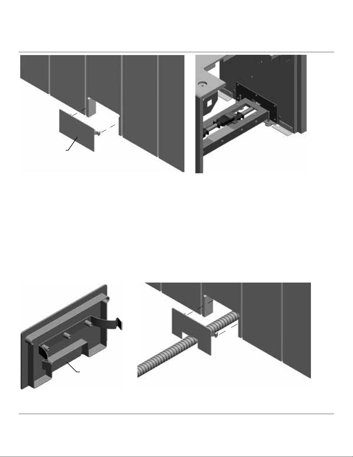
AE
AF
AE
G
34. Position Shroud (G) around top of Column. Press down onto Base Top.
35. Secure Shroud in place with 2 Shroud Clamps (AE) and Pan Head Screw (AF).
AF
H
37. Lay chain on the oor with the open side of both end links point up. Then use a
Straight / Flat blade screwdriver to open each clasp.
Z
© 2017 Herman Miller, Inc. Zeeland, Michigan. Printed in the U.S.A.
TM
Sense, Setu, Tu, Traverse and Locale are among the trademarks of Herman Miller, Inc.
Illustrations and specifications are based on the latest product information available at the time of publication.
The right is reserved to make changes in design and specifications at any time, without notice, and also to discontinue products.
36. Insert Wire Guide (H) into Column.
Press down to snap into Shroud and
steel bracket.
Part no. 1bch5g rev D.
13
Page 14

38. Fully raise the column before installing chain and cords. Feed your cords from the
front all the way through the column and out the back side.
39. Place your cords into the chain, either end of the chain can be the top side. Then
close all but the top 3 or 4 links open for ease of attaching brackets later.
Z
© 2017 Herman Miller, Inc. Zeeland, Michigan. Printed in the U.S.A.
TM
Sense, Setu, Tu, Traverse and Locale are among the trademarks of Herman Miller, Inc.
Illustrations and specifications are based on the latest product information available at the time of publication.
The right is reserved to make changes in design and specifications at any time, without notice, and also to discontinue products.
Part no. 1bch5g rev D.
14
Page 15

40. Feed energy chain through the grommet which is even with the work base top and
then through the top of the plate on the leg column making sure the snap open side
is facing towards the desk side of the leg. (Make sure the plastic grommet is installed
before you feed the chain through)
41. Attach top bracket.
Z
© 2017 Herman Miller, Inc. Zeeland, Michigan. Printed in the U.S.A.
TM
Sense, Setu, Tu, Traverse and Locale are among the trademarks of Herman Miller, Inc.
Illustrations and specifications are based on the latest product information available at the time of publication.
The right is reserved to make changes in design and specifications at any time, without notice, and also to discontinue products.
Part no. 1bch5g rev D.
15
Page 16

42. After the chain is through the grommet and inside the work base install the
bottom bracket to the chain.
Z
© 2017 Herman Miller, Inc. Zeeland, Michigan. Printed in the U.S.A.
TM
Sense, Setu, Tu, Traverse and Locale are among the trademarks of Herman Miller, Inc.
Illustrations and specifications are based on the latest product information available at the time of publication.
The right is reserved to make changes in design and specifications at any time, without notice, and also to discontinue products.
Part no. 1bch5g rev D.
16
Page 17

BOLT
BRACKET
LEG BRACKET
WASHER
NUT
43. Install the bottom bracket to the upper inner framework hardware that attaches
the leg to the upper part of the work base. The bolt goes through bracket, then the
triangular opening of the leg attachment bracket, with the washer and nut on the
other side. (For a clearer view pictures do not show the chain)
Z
© 2017 Herman Miller, Inc. Zeeland, Michigan. Printed in the U.S.A.
TM
Sense, Setu, Tu, Traverse and Locale are among the trademarks of Herman Miller, Inc.
Illustrations and specifications are based on the latest product information available at the time of publication.
The right is reserved to make changes in design and specifications at any time, without notice, and also to discontinue products.
Part no. 1bch5g rev D.
17
Page 18

44. At the top of the leg feed the cords into the trough area and close the top clasps
that remained open on both ends of the chain.
45. Push the chain as far forward as possible while keeping the top bracket ush on
the top plate.
Z
© 2017 Herman Miller, Inc. Zeeland, Michigan. Printed in the U.S.A.
TM
Sense, Setu, Tu, Traverse and Locale are among the trademarks of Herman Miller, Inc.
Illustrations and specifications are based on the latest product information available at the time of publication.
The right is reserved to make changes in design and specifications at any time, without notice, and also to discontinue products.
Part no. 1bch5g rev D.
18
Page 19

46. Screw bracket down to the top plate using the self-drilling screws. (NOTE: On L and
T desks, only one side of the bracket will screw onto the top plate)
Z
© 2017 Herman Miller, Inc. Zeeland, Michigan. Printed in the U.S.A.
TM
Sense, Setu, Tu, Traverse and Locale are among the trademarks of Herman Miller, Inc.
Illustrations and specifications are based on the latest product information available at the time of publication.
The right is reserved to make changes in design and specifications at any time, without notice, and also to discontinue products.
Part no. 1bch5g rev D.
19
Page 20

Pulled Taught
Cable Loop
47. Wrap Control Switch Cable underneath z rails so it is trapped in gap between
two castings.
48. Press Control Switch cable rmly into cable retaining guides in Work Surface
Supports. Make loop in cable to take up slack in cable.
CARE Point - cable needs to be taught to aid retention.
T
Z
© 2017 Herman Miller, Inc. Zeeland, Michigan. Printed in the U.S.A.
TM
Sense, Setu, Tu, Traverse and Locale are among the trademarks of Herman Miller, Inc.
Illustrations and specifications are based on the latest product information available at the time of publication.
The right is reserved to make changes in design and specifications at any time, without notice, and also to discontinue products.
AK
49. Gather all cabling
and capture with Cable
Clamp (T).
50. Install Flange
Screw (AK).
Part no. 1bch5g rev D.
20
Page 21

AJY
V
W
X
AJ
Y
51. Place Work Surface (V) bottom side up on clean, dry, padded surface.
52. Mount Control Box (W) onto Work Surface with Button head Screws (X).
53. Install 4 Mushroom Fasteners (Y) onto Work Surface with 4 Button Head
Flange Screws (AJ).
Z
54. Place Work Surface onto Work Surface Supports.
55. Insert Mushroom Fasteners on Work Surface into keyhole slots in column.
56. Push Work Surface over to engage Mushroom Fasteners into slots.
57. Secure Work Surface to Rails and Surface Supports with Flange Screws (Z).
Z
© 2017 Herman Miller, Inc. Zeeland, Michigan. Printed in the U.S.A.
TM
Sense, Setu, Tu, Traverse and Locale are among the trademarks of Herman Miller, Inc.
Illustrations and specifications are based on the latest product information available at the time of publication.
The right is reserved to make changes in design and specifications at any time, without notice, and also to discontinue products.
Part no. 1bch5g rev D.
21
Page 22

X
58. Make all cable connections.
59. Pull Control Switch into position. Secure Switch to Work Surface with 2
Button Head Machine Screws (X).
AA
60. Before installing Wire Cover (AA): Ensure Hinges are pushed furthest back
and rotated as far up as possible.
Z-Rail Slot
61a. Slide Left Hinge Hook into Z-Rail Slot, then align Right Hinge. (Right Hand Desk
shown)
Z
© 2017 Herman Miller, Inc. Zeeland, Michigan. Printed in the U.S.A.
TM
Sense, Setu, Tu, Traverse and Locale are among the trademarks of Herman Miller, Inc.
Illustrations and specifications are based on the latest product information available at the time of publication.
The right is reserved to make changes in design and specifications at any time, without notice, and also to discontinue products.
Part no. 1bch5g rev D.
22
Page 23

62b. Alternatively, slide Left Hinge into Z-Rail then align Right Hinge. (Left Hand
Desk shown)
63. Slide Right Hinge into Z-Rail. Right screw hole will align with Right Hand
Desk. Left screw hole will align with Left Hand Desk.
Z
© 2017 Herman Miller, Inc. Zeeland, Michigan. Printed in the U.S.A.
TM
Sense, Setu, Tu, Traverse and Locale are among the trademarks of Herman Miller, Inc.
Illustrations and specifications are based on the latest product information available at the time of publication.
The right is reserved to make changes in design and specifications at any time, without notice, and also to discontinue products.
Part no. 1bch5g rev D.
23
Page 24

Hook
Slot
64. Lift and pull assembly to engage both hooks into slots in Z-Rail.
Z
65. Install Button Head Flange Screw (Z). Repeat for other Hinge.
AB
66. Place Wire Tray (AB) into Cable Cover.
Z
© 2017 Herman Miller, Inc. Zeeland, Michigan. Printed in the U.S.A.
TM
Sense, Setu, Tu, Traverse and Locale are among the trademarks of Herman Miller, Inc.
Illustrations and specifications are based on the latest product information available at the time of publication.
The right is reserved to make changes in design and specifications at any time, without notice, and also to discontinue products.
Part no. 1bch5g rev D.
24
Page 25

67. Slide edge of Wire Tray Under 2 Tabs in Cable Cover.
Mushroom
Fastener
Hook
68. Press in on middle of Wire Tray until lip ts under single bracket on Cable
Cover.
69. Close cover by engaging Hooks on Cable Cover onto Mushroom Fasteners.
AD
AC
Bottom Shelf
70. Return Bottom Shelf to Base.
71. Install Shelf Pins (AD) into Shelf locations in base. Set Shelf (AC) onto Pins.
Z
© 2017 Herman Miller, Inc. Zeeland, Michigan. Printed in the U.S.A.
TM
Sense, Setu, Tu, Traverse and Locale are among the trademarks of Herman Miller, Inc.
Illustrations and specifications are based on the latest product information available at the time of publication.
The right is reserved to make changes in design and specifications at any time, without notice, and also to discontinue products.
Part no. 1bch5g rev D.
25
Page 26

72. Return Access Panels and Doors, if removed, to Base.
Disassembly and Recycling:
Materials Identication and Segregation:
Where possible, plastic components are marked with ASTM recycling codes. Use
these codes to identify material type for recycling. Non-marked components should
be treated as mixed plastic. Ferrous metals can be identied using a small magnet
for recycling. Non-ferrous metals should be separated and recycled separately.
To disassemble product, reverse the above installation steps and also do the following.
Z
© 2017 Herman Miller, Inc. Zeeland, Michigan. Printed in the U.S.A.
TM
Sense, Setu, Tu, Traverse and Locale are among the trademarks of Herman Miller, Inc.
Illustrations and specifications are based on the latest product information available at the time of publication.
The right is reserved to make changes in design and specifications at any time, without notice, and also to discontinue products.
Part no. 1bch5g rev D.
26
Page 27

Hinge
Door
1. Disengage the hinge from the base and
remove the door.
Door
2. Using a phillips head screw driver uninstall
the screws and remove hinge from door.
Repeat step 1 and 2 to remove other side
door.
Back Panel
Access Panel
3. Using a straight head screw driver remove the access and back panel from both
side of the base.
Z
© 2017 Herman Miller, Inc. Zeeland, Michigan. Printed in the U.S.A.
TM
Sense, Setu, Tu, Traverse and Locale are among the trademarks of Herman Miller, Inc.
Illustrations and specifications are based on the latest product information available at the time of publication.
The right is reserved to make changes in design and specifications at any time, without notice, and also to discontinue products.
Part no. 1bch5g rev D.
27
Page 28

Shelves
End Panel
Shelves
4. Using a straight head screw driver remove end panel. Remove the dowel pins and
spreading bolt - minix.
5. Remove the shelves from the base.
6. Using the phillips head screw driver remove
8 screws under the inner top.
7. Remove the thin top.
Inner Top
Z
© 2017 Herman Miller, Inc. Zeeland, Michigan. Printed in the U.S.A.
TM
Sense, Setu, Tu, Traverse and Locale are among the trademarks of Herman Miller, Inc.
Illustrations and specifications are based on the latest product information available at the time of publication.
The right is reserved to make changes in design and specifications at any time, without notice, and also to discontinue products.
Thin Top
Part no. 1bch5g rev D.
28
Page 29

Stretcher
8. Using a phillips head screw driver remove screws from stretcher and remove the
stretcher from the inner side panel.
Divider
9. Using a phillips head screw driver loosen the screw bolts from the front RH divider
and LH divider. Remove the both dividers from back dividers.
Z
© 2017 Herman Miller, Inc. Zeeland, Michigan. Printed in the U.S.A.
TM
Sense, Setu, Tu, Traverse and Locale are among the trademarks of Herman Miller, Inc.
Illustrations and specifications are based on the latest product information available at the time of publication.
The right is reserved to make changes in design and specifications at any time, without notice, and also to discontinue products.
Part no. 1bch5g rev D.
29
Page 30

Hinge Clip
Divider
10. Using a phillips head screw driver loosen the screws and remove the
screws and hinge clips from the panel.
11. Using a phillips head screw driver loosen the screws from hot box weldment lower
and upper and remove the screws and panels.
Z
© 2017 Herman Miller, Inc. Zeeland, Michigan. Printed in the U.S.A.
TM
Sense, Setu, Tu, Traverse and Locale are among the trademarks of Herman Miller, Inc.
Illustrations and specifications are based on the latest product information available at the time of publication.
The right is reserved to make changes in design and specifications at any time, without notice, and also to discontinue products.
Part no. 1bch5g rev D.
30
Page 31

12. Using a phillips head screw driver loosen the screws and separate the panels.
Z
© 2017 Herman Miller, Inc. Zeeland, Michigan. Printed in the U.S.A.
TM
Sense, Setu, Tu, Traverse and Locale are among the trademarks of Herman Miller, Inc.
Illustrations and specifications are based on the latest product information available at the time of publication.
The right is reserved to make changes in design and specifications at any time, without notice, and also to discontinue products.
Part no. 1bch5g rev D.
31
 Loading...