

Page 1
INSTRUCTIONS
Part# 1002482-02
11/17/06
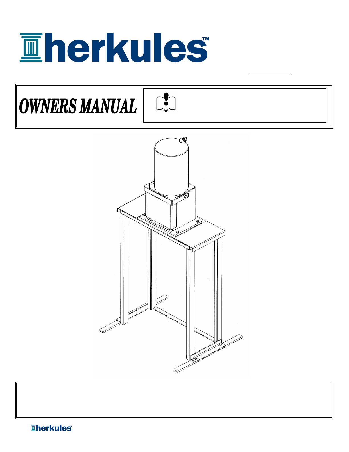
Model: OFC1
This manual contains important information concerning the
installation and operation of the crusher listed above.
Read manual thoroughly and keep for future reference
Herkules Equipment Corporation 2760 Ridgeway Court Walled Lake, MI 48390-1662 USA
248-960-7100 800-444-4351 Fax 248 960-7109
Patents USA 7070167 4793369, 4960142, 5174317, 5193561, 5485860 Canada 1299468 & Patents Pending
Page 1 of 8
Page 2

Table of Contents
Warnings …………………………………………………………………………………………………………………. 3
Model Information (List of models with descriptions and data) ……………………………………………… 4
Installation
Inspection
Operation ………………………………………………………………………………………………………………… 6
Safety Information ………………………………………………………………………………………………… 7
Maintenance ………………………………………………………………………………………………………… 7
Drawings with part lists: ……………………………………………………………………………………………. 8
……………………………………………………………………………………………………………….. 5
………………………………………………………………………………………………………………… 6
Warning Symbol Caution Symbol
WARNING
This symbol alerts you to the possibility of
serious injury or death if you do not follow
the instructions.
Serial Number
Model Number
Purchase Date
Distributor
CAUTION
This symbol alerts you to the possibility of
damage to or destruction of equipment if you
do not follow the instructions.
PATENT NUMBERS
This product has patent protection under
one or more of the following patent numbers:
7070167, 5485860, 5193561, 5174317
4960142, 4793369, 1299468
and Patents Pending
website: www.herkules.us
1002742
Page 2 of 8
Page 3

WARNING
FAILURE TO HEED THE FOLLOWING WARNINGS MAY RESULT
IN PERSONAL INJURY AND/OR PROPERTY DAMAGE.
1 Herkules will not be held responsible for any personal injury and/or property damaged caused
due to owner/operator failure to follow the warnings and cautions listed in this manual.
2 Read and understand all warnings, cautions and instructions before operating this equipment.
3 It is the owner/operators responsibility to maintain the legibility of all warning and instruction labels.
4 Do not alter or modify any part of this equipment.
5 Do not attempt to bypass the door/latch interlock system. The door interlock is provided for operator safety.
6 DO NOT open the door while the unit is operating. Always wait for the crusher to cycle completely.
7 Crush only intended matter for the crusher.
8 Always wear safety glasses when operating the crusher.
9 Always wear suitable industrial gloves when handling crushed objects to prevent injury.
10 Check equipment regularly for proper operation and repair or replace worn or damaged parts immediately.
11 Any crusher that appears to be damaged in any way, is badly worn or operates abnormally shall be removed
from use until repairs are made. Use only manufacturer's approved accessories and service parts.
Contact a factory authorized service center for repairs.
12
DO NOT REMOVE THIS LABEL. REPLACE IF DAMAGED.
Page 3 of 8
Page 4
Model Information
SPECIFICATIONS
Maximum crushing pressure 3.75 tons
Capacity One filter
Filter type Car/light truck
Filter crush Up to 80%
Residual oil removed from crushed filter 95 - 98%
Time to crush filter 15 - 30 seconds
Overall width 30"
Overall height 69-1/4"
Overall depth 13"
Chamber width 10"
Chamber height 11-1/2"
Chamber depth 10"
Required air pressure 100-120 p.s.i.
Total weight 250 Ibs.
DESCRIPTION
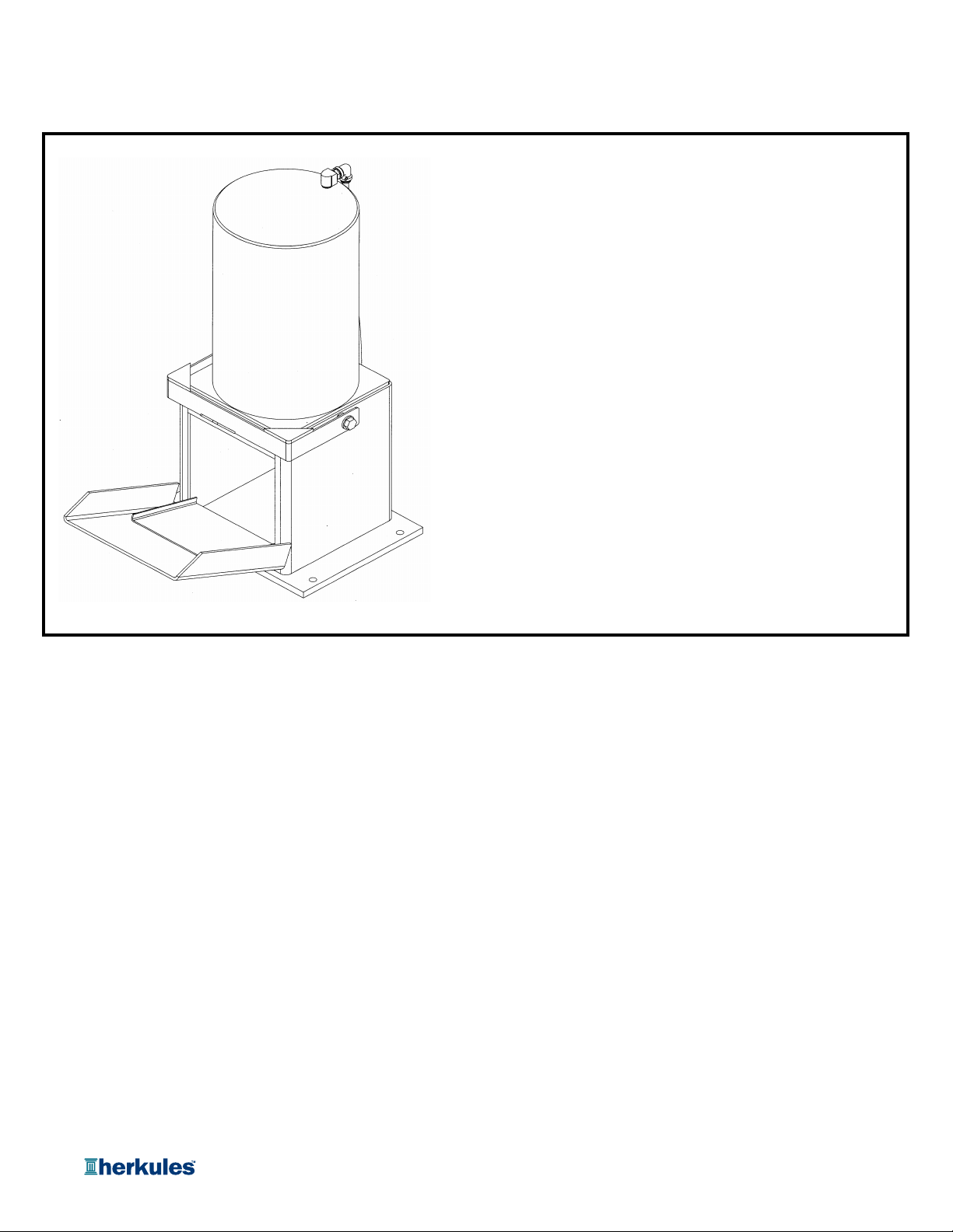
Model OFC1 is a production crusher capable of crushing one filter at one time. The crusher is designed for
automotive and light truck shops to crush and dispose of used oil filters in an environmentally correct manner. The
crusher provides the following features:
• Powerful 3.75 ton cylinder assures the force necessary to do the job when crushing oil filters.
• Operates with external air only. No electric power is required.
• Safe double lock door protects operator.
• Removes 95-98% of residual oil from oil filter.
• Easy connection for oil drain off.
• One oil filter capacity.
Page 4 of 8
Page 5
OWNER/OPERATOR RESPONSIBILITY
r
It is the responsibility of the owner/operator to properly use and maintain this equipment.
The instructions and warnings contained in this manual shall be read and understood by the owner/operator prior
to operating this equipment.
If an owner/operator does not understand English, the contents of this manual shall be explained in the owner/
operator native language to assure the owner/operator comprehends.
It is the responsibility of the owner/operator to maintain the legibility of all warning and Instruction labels.
The owner/operator shall retain this manual for future reference to important warnings, operating and maintenance
instructions.
INSTALLATION
1 Bolt stabilizer feet to the bottom of the stand with the 3/8-16 X 3/4" bolts.
2 Bolt cabinet to stand with the 3/8-16 X 2-1/2" bolts, nuts and washers provided.
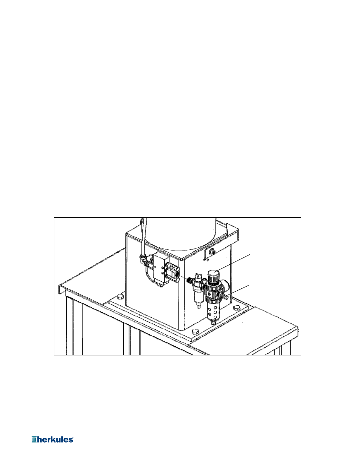
3 Assemble the Filter/Regulator assembly using a thread sealer. Note: Make sure that the arrows are
pointing toward the unit (see fig 1).
Fig. 1
Filter/Regulator
3/8 NPT Air Inlet
Oile
4 Fill the oiler with 30W non-detergent oil before attaching airline. NEVER REMOVE OILER WITH AIR ATTACHED
5 Route your airline safely to prevent tripping and possible tipping the machine over. Use an unrestricted
airline (no quick connects) at 100-120 psi and 3/8" to 1/2" ID.
6 Attach the 3/4" nipple to the bottom of the unit and select a waste oil container to put under the unit. A
hose may be run from the outlet to a remote container.
7 Turn on air and set regulator to 100-120 psi.
Page 5 of 8
Page 6

INSPECTION
Prior to operation a visual Inspection shall be made. Check crusher for leaks, worn or missing parts.
Periodically check oil level in oiler. DO NOT RUN WITHOUT OIL.
Any crusher that appears to be damaged in any way, is badly worn or operates abnormally shall be removed
from use until repairs are made. Contact a factory authorized service center for repairs.
If over pressurizing of the equipment is believed to have occurred, contact a factory authorized service center for
inspection of the crusher.
An annual inspection by a factory authorized service center is recommended.
OPERATION
1 Turn the external air supply on.
2 Verify the pressure gauge on the pressure regulator/filter reads between 100 and 120 p.s.i. Adjust the
regulator as required.
NOTE:
If the external air supply is less than 100 p.s.i., the crusher will operate but the crushing performance
is reduced.
3 Lift the door latch and pull the door down to gain access to the crushing chamber.
4 Place one filter, vertically in chamber, open side down.
5 Close door and pull down latch handle. The crushing operation will start immediately.
6 Within 15-30 seconds, depending on filter size and weight, the filter will be crushed 70-79% of its original
size.
7 The regulator gauge will show when max pressure is reached. A few seconds at max pressure will give
maximum crush.
8 Lift door latch and open door.
9 Remove the crushed oil filter and dispose of it in an environmentally correct manner. NEVER REACH INSIDE
UNIT BEFORE RAM RETURNS TO THE TOP.
WARNING
The crushing mandrel may be still moving when the
door is opened. Wait until the mandrel stops before
placing hand in chamber.
WARNING
A crushed oil filter may have jagged metal edges. Use
good industrial work gloves to protect the hands
when removing a crushed oil filter.
Page 6 of 8
Page 7

SAFETY INFORMATION
.
.
Read and understand all warnings, cautions and instructions before operating this equipment. Caution should be used
when operating this equipment as personal injury and/or property damage can result from equipment misuse. Adequate
personal protection is recommended to prevent splashing of oil on the skin or in the eyes.
Check crusher and stand mounting for tightness.
•
•
Check stabilizer bolts for tightness.
•
Check Air Line and waste oil line for loose connections, constrictions, and non-tripping routings.
•
Check that the Air Line delivers 100-120 psi to the crusher Filter-Regulator.
SAFETY OPERATIONS
•
Do not crush aerosol cans, glass, or content filled metal containers. Dangerous shrapnel explosions could happen.
•
Place only one filter in chamber, vertically only, open side down
• Never place more than one filter in the crushing chamber at any time.
•
Operate only with slip-in tray in place
MAINTENANCE
•
Check oiler level weekly to keep adequate oil in the air cylinder. Use 30W non-detergent or air compressor oil
to two-cycle engine oil.
Turn the drain valve at the bottom of the filter/regulator counterclockwise once a week to release water filtered from
•
the air system.
Periodically check air and oil fittings for tightness. Check stand and floor mount bolts.
•
•
Remove paper and paint chips from cabinet interior weekly to minimize oil drain blockage.
•
Check the ram bolt periodically for tightness.
Page 7 of 8
Page 8
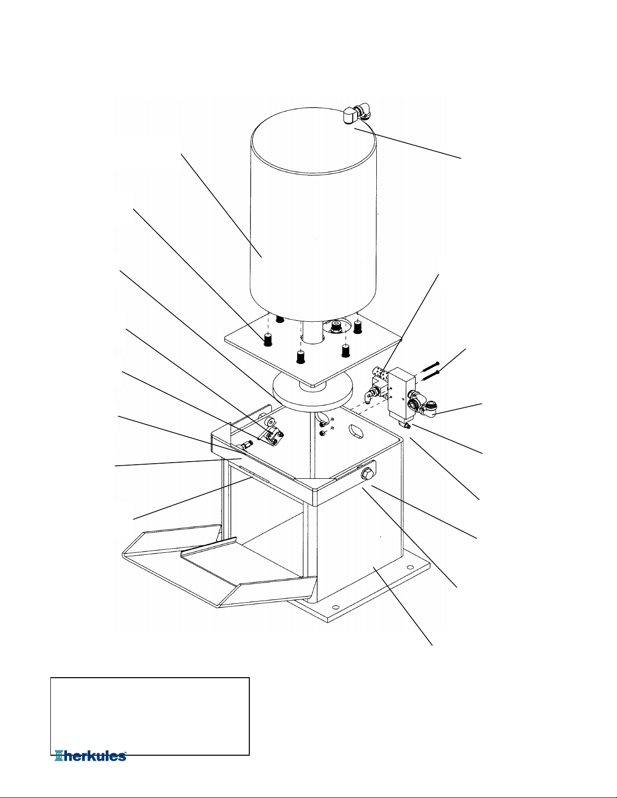
SERVICE PARTS
A
Hex Bolt
#83M
Ram Plate
#12142
Bolt Handle Switch
#10342
Limit Valve
#M1C
Tube Fitting
#T3
Air Cylinder
#008-240
Street Elbow
#M6A
Silencer
#009-142
Screw BHSC
#008-246
Tube Fitting
#T30
Limit Valve
#M2
Handle Weldment
#12143
dditional Parts not shown:
Nylon Tubing 5/32”M5
Nylon Tubing 3/8”M7APE
Stand Assembly 12144
Stabilizer Bar10244
Pilot Valve
#1001357
Tube Fitting
#002-129
Hex Bolt
#83E
Flat Washer
#85D
Housing Assembly
#10051
Page 8 of 8
 Loading...