

Heritage MCM-8 Preliminary User Manual

© 2017 All the documentation included in this manual is copyrighted by Heritage Audio S.L. All
rights are reserved. No part of this ma nual may be reproduced, copied, translated or transmitted, in any
form or by any means without the prior written permission of Heritage Audio S.L.
Heritage Audio S.L. reserves the right to make improvements to the products described in this
manual at any time without notice. The information in this manual is intended to be accurate and reliable.
However, Heritage Audio S.L. assumes no responsibili ty for its us e; nor for any infringements of rights of
third parties which may result for its use.
MCM-8
PRELIMINARY USER GUIDE v1.1
MCM-8 Iss1
Preliminary User Guide v1.1
2
INTRODUCTION
The MCM-8 is an OST
TM
8 channel 500 Series Enclosure WITH mixer functions.
OST is a Heritage Audio proprietary technology which eliminates module’s interaction through
the power supply feeding each slot with independent supply stages.
The mixer follows a passive voltage summing topology, having the gain loss restored by a
classic 1073 type class A output stage.
The outputs of the 8 slots are hardwired to the 8 summing mixer’s main inputs, therefore
independent use of the 500 series modules and summing mixer features is not possible.
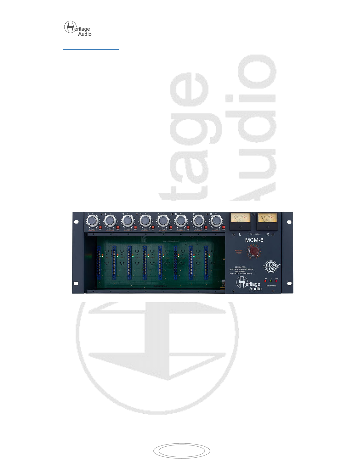
FRONT PANEL OVERVIEW
Upper row on the front panel is dedicated to the 8 mixer’s main inputs.
Controls per channel are as follows:
- ON: When pressed, the output of the slot is added to the mix bus. When depressed,
it’s muted.
- FADER: Attenuates the signal sent to the mix bus from unity to minus infinity. Fader all
clockwise means unity gain, whilst 12 o’clock means an approximate 20 dB of
attenuation. (or -20dB of gain ).
- PAN: Places the signal within the stereo spectrum, left, center, right or any
intermediate setting. The panoramic law follows a standard in which if a 0dB signal is
hard panned, it is -3dB when center panned.
Lower zone is dedicated to the 500 series modules. Any module following the API protocol
(both mechanically and electrically) will be compatible with the unit.
MCM-8 Iss1
Preliminary User Guide v1.1
3
Right part of the unit is dedicated to the mixer’s center section, as follows:
- VU Meters: Measuring the average level at the master outputs.
- Master Fader: Attenuates the Mix’s output from unity to minus infinity. The control
has a stepped feel for easy recall of settings. Fader all clockwise means unity gain,
whilst 12 o’clock means an approximate 20dB of attenuation.
At the bottom right there are LEDs showing the correct status of the external power source.
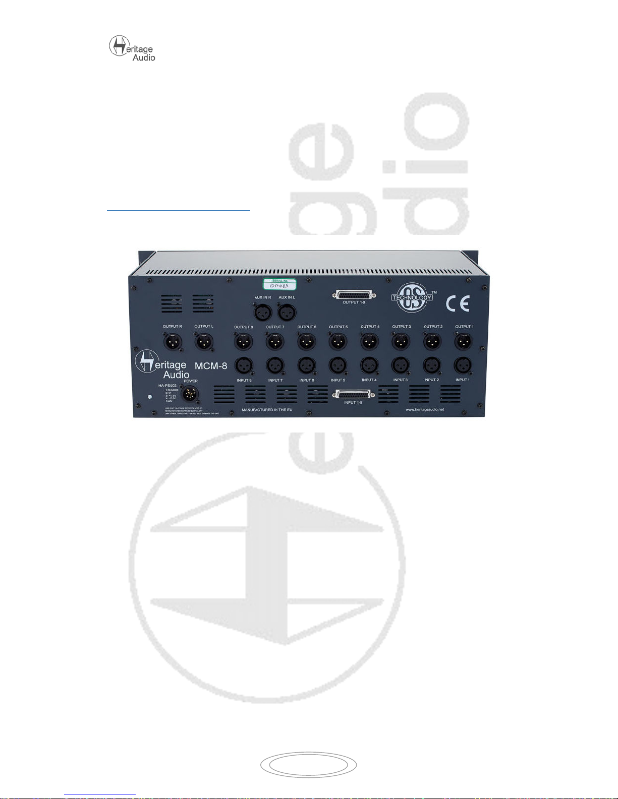
BACK PANEL OVERVIEW
Upper row on the back panel corresponds to the individual XLR and combined DSUB channel
outputs.
Lower row corresponds to the individual XLR and combined DSUB channel inputs.
Both DSUB connectors are wired following the TASCAM protocol.
Stereo Mix output is located far left, on a pair of male XLR connectors.
Aux Inputs are located above the 8 inputs , on a pair of female XLR connectors. They´re
hardwired Left and Right and are unity gain.
External Power Supply connector is located on the bottom left corner.
 Loading...