

Page 1

Page 2
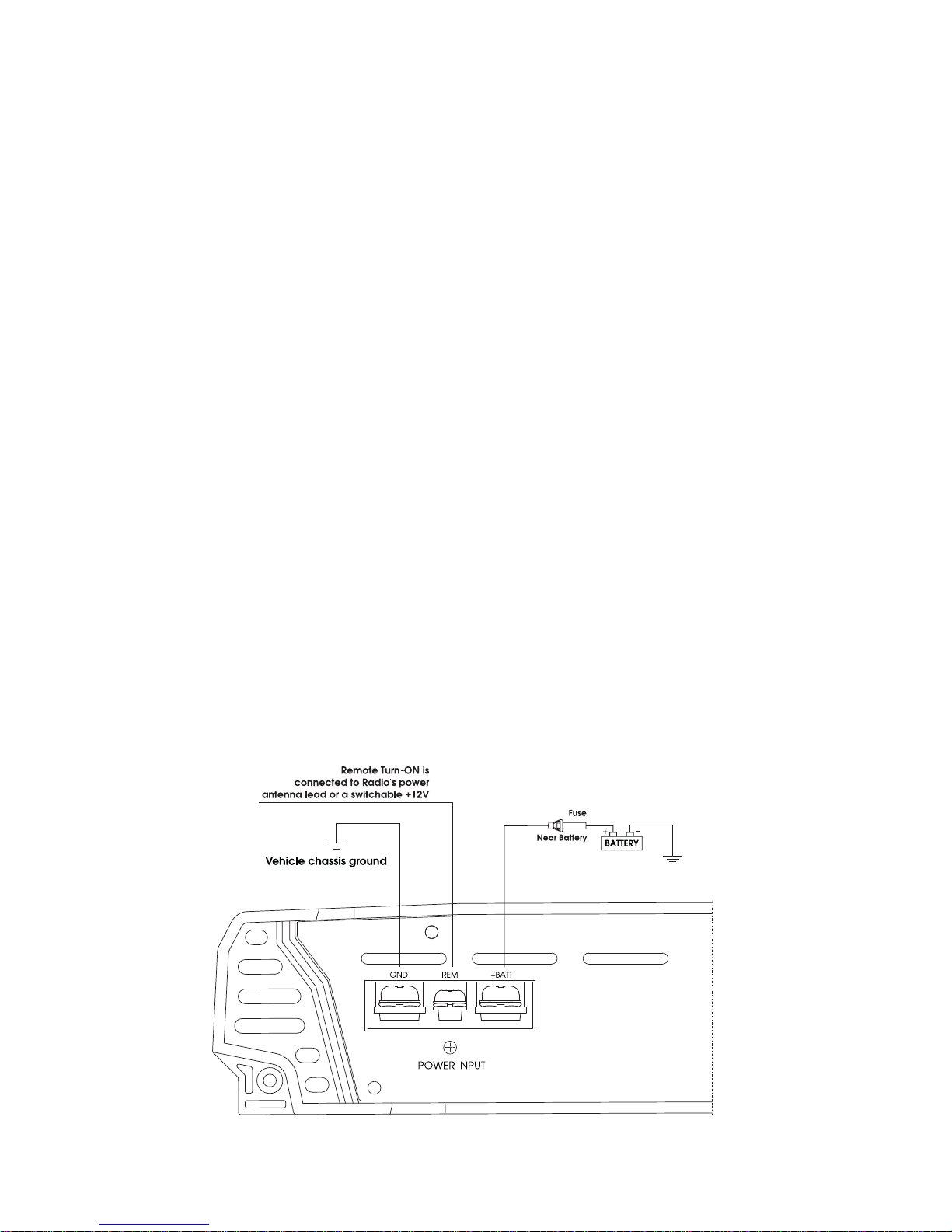
ONNECTING THE POWER
C
UTION:
CA
AS A PRECAUTION, DISCONNECT THE POWER WIRE FROM THE BATTERY WHILE MAKING THE
POWER AND GROUND CONNECTIONS TO THE AMPLIFIER.
4/8 GA
UGE(Thicker if planning for additional Amplifiers) wire is recommended for
both the power and ground wires 12 Gauge, for the remote turn-on wire 16 Gauge.
Both types are available at most Mobile Audio Dealers or Installation Shop.
(1) Ground : To Vehicle Chassis
To avoid unwanted ignition noise caused by ground loop, it is essential that the
Amplifier be grounded to a clean, bare, metal surface of the vehicle's Chassis
NO
TE :
GROUND WIRE SHOULD NOT BE EXTENDED MORE THAN 3 FT. (1 METER).
(2) +12
Volt(Fused) Constant Power: To Battery (+)
Due to the power requirements of the Amplifier, this connection should be made
directly to the positive (+) terminal of battery. For safety measures, install an in-line
Fuse Holder (not included) as close to the battery positive (+) terminal as
possible with an ampere rating; not to exceed total value of fuses in Amp.
(3) Remote Turn-On Input: To remote turn-on output of Car Stereo
This Amplifier is turned "ON" remotely when the vehicle's stereo is turned "ON".
TE :
NO
IF YOUR RADIO DOES NOT HAVE A +12 VOLT OUTPUT LEAD WHEN THE RADIO IS TURNED ON, THE "REMOTE"
TERMINAL ON THE AMPLIFIER CAN BE CONNECTED TO VEHICLE'S ACCESSORY CIRCUIT THAT IS LIVE WHEN THE KEY
IS "ON".
Page 3
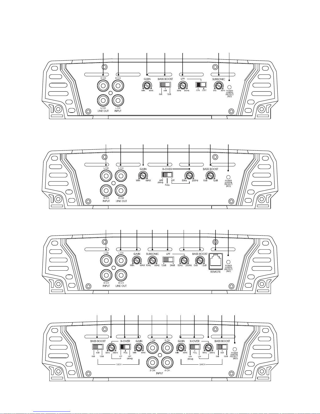
P
ANEL LAYOUT
HTG157 FRONT VIEW
HTG237 / HTG257 FRONT VIEW
19
1 9 2 4 4 6 8
2 6 843
HTG2100D FRONT VIEW
HTG447 FRONT VIEW
1 9 2 3 5 5 6 7 8
1 12 24 44 46 6 8
Page 4
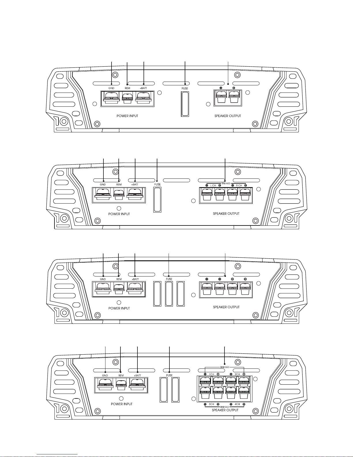
P
ANEL LAYOUT
HTG157 REAR VIEW
10 11
HTG237 / HTG257 REAR VIEW
10 11 12 13 14
12
13
14
HTG2100D REAR VIEW
HTG447 REAR VIEW
11 12 13
10
10 11 12 13
14
14
Page 5

C
ONTROL FUNCTIONS
1.
RCA input jacks
These RCA input jacks are for use with source units that have RCA or Line level
outputs. A source unit with a minimum level of 200mV is required for proper operation.
The use of high quality twisted pair cables is recommended to decrease the possibility
of radiated noise entering the system.
2. GAIN Control
The level control will match the amplifiers sensitivity to the source units signal voltage.
The Operating range is 200mV minimum to 6V maximum.
C
AUTION: Do not run the amplifier in high volume for long time, otherwise the loudspeakers will be damaged.
SUBSONIC
3.
HTG157:The frequency can be adjusted between 0Hz and 80Hz.
HTG2100D:The frequency can be adjusted between 10Hz and 60Hz.
4. X-OVER
* Full pass x-over switch
When the switch is in the “Full” position, the full range is bypassed.
* Low pass x-over switch
When the switch is in the “LPF” position, frequencies lower than the low pass frequency
setting are passed.
HTG157/HTG237/HTG257/HTG447 : The frequency can be adjusted between 50Hz and 250Hz.
* High pass x-over switch
When the switch is in the “HPF” position, frequencies higher than the high pass
frequency setting are passed.
HTG237/HTG257/HTG447 : The frequency is 80Hz.
5. Low pass x-over frequency control
This control is used to select the desired low pass x-over frequency.
The frequency can be adjusted between 50Hz and 250Hz.
6. Bass BOOST
HTG237/HTG257/HTG2100D : The boost can be adjusted between 0dB to12dB.
HTG157/HTG447 : The boost can be selected among 0dB, 6dB and 12dB.
7. REMOTE
Controls the subwoofer amplifier gain, from a remote location for ease of adjustment
during listening.
arning: Do not connect a level control knob from other manufacturers to the Remote Sub Level
W
Control of any amplifier. Even though the connectors fit properly, the control knob and connector
pin positions may be different and the amplifier will be damaged.
Page 6

C
ONTROL FUNCTIONS
LED
8.
Will illuminate GREEN to indicate the amplifier is on and operating normally, and will
be illuminated RED if the amplifier shuts down due to short circuit, DC offset, or
overheating detected by on board protection circuitry
9. Auxiliary outputs
The Auxiliary outputs offer HERTIAGE amplifiers easy, unlimited system expansion.
Route RCA’s from the line out of the first amplifier to the line input of a second
amplifier when using a single source output.
10. GND
Connect this terminal directly to the sheet metal chassis of the vehicle, using the
shortest wire necessary to make this connection. Always use wire of the same gauge
or larger than the (+)12 volt power wire. The chassis connection point should be
scraped free of paint and dirt. Use only quality crimped and/or soldered connectors
at both ends of this wire.
arning : Do not connect this terminal directly to the vehicle battery ground terminal or any other factory
W
ground points.
11.
Remote Turn On
This terminal turns on the amplifier when (+)12 volt is applied to it. Connect it to the
remote turn on lead of the head unit or signal source.
12 . (+)12 Volt Power
Connect this terminal through a FUSE or CIRCUIT BREAKER to the positive terminal of
the vehicle battery or the positive terminal of an isolated audio system battery.
W
arning: Always protect this power wire by installing a fuse or circuit breaker of the appropriate
size within 12 inches of the battery terminal connection.
FUSE
13.
These fuses protect the amplifier against internal electrical damage and are meant to
protect the amplifier only. All other power connections should be fused at the source.
14. SPEAKERS
Connect subwoofers to these terminals.
Page 7
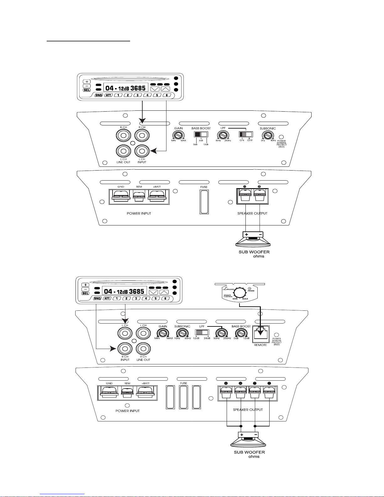
ystem Diagrams
S
MONO Channel S
HTG157
ystem Design #1
HT
G2100D
2-4
2-4
Page 8
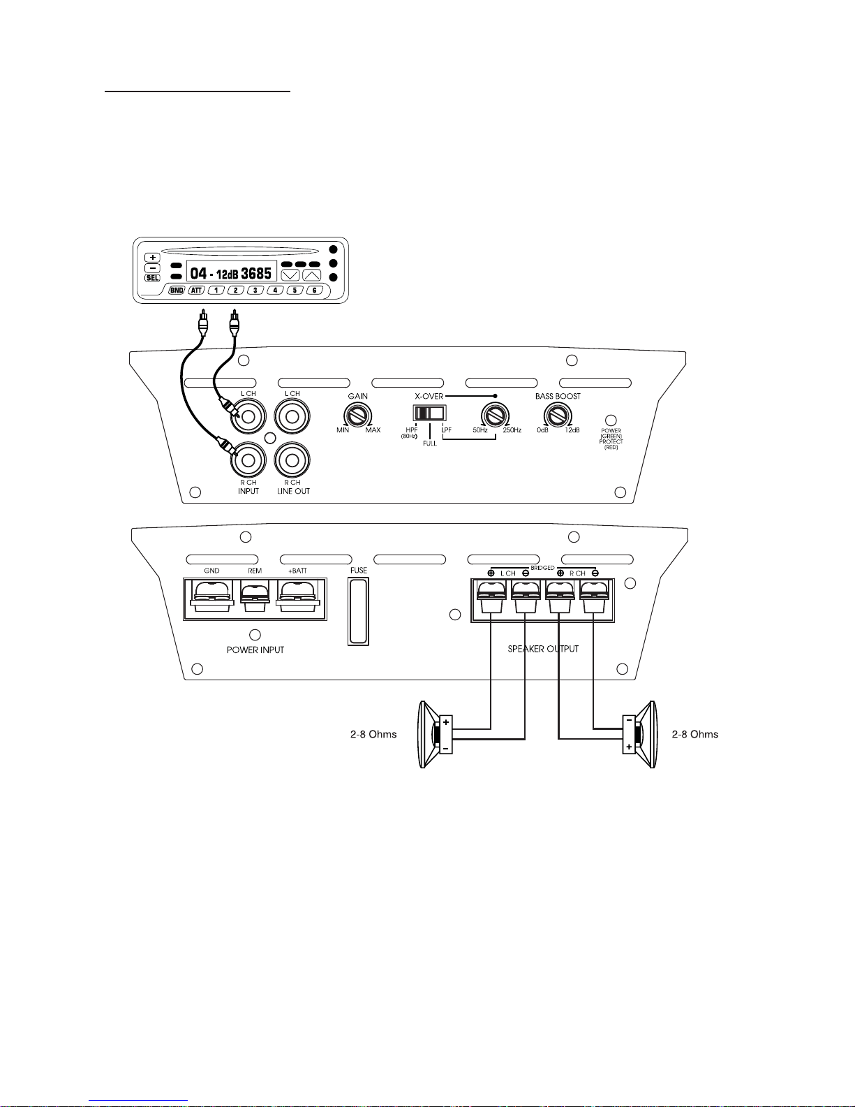
ystem Diagrams
S
2Channel S
HT
G237 / HTG257
ystem Design #1
Page 9
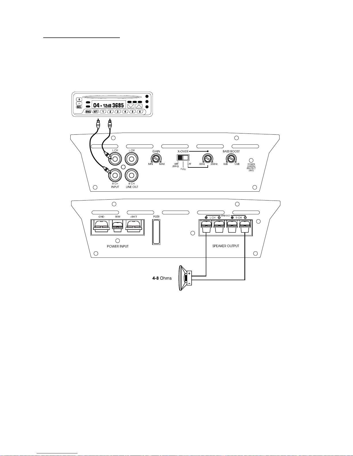
ystem Diagrams
S
2Channel S
HT
G237 / HTG257
ystem Design #2
Page 10
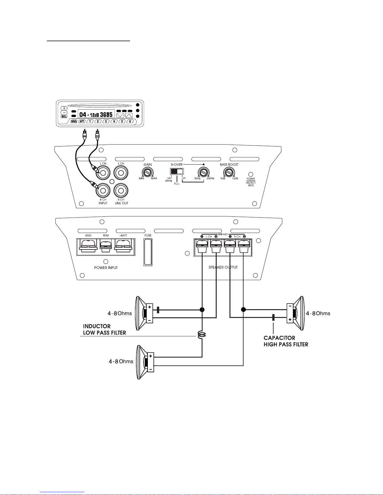
ystem Diagrams
S
2Channel S
HT
G237 / HTG257
ystem Design #3
Page 11
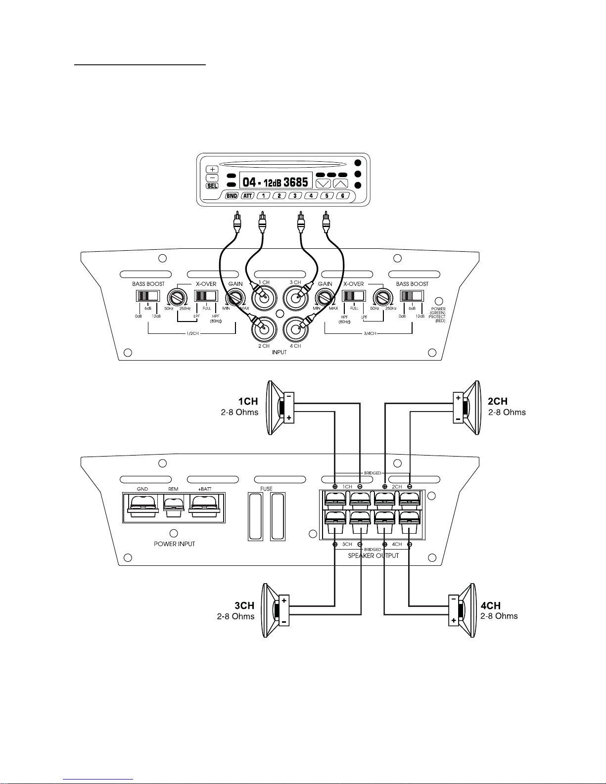
ystem Diagrams
S
4Channel S
HT
G447
ystem Design #1
Page 12
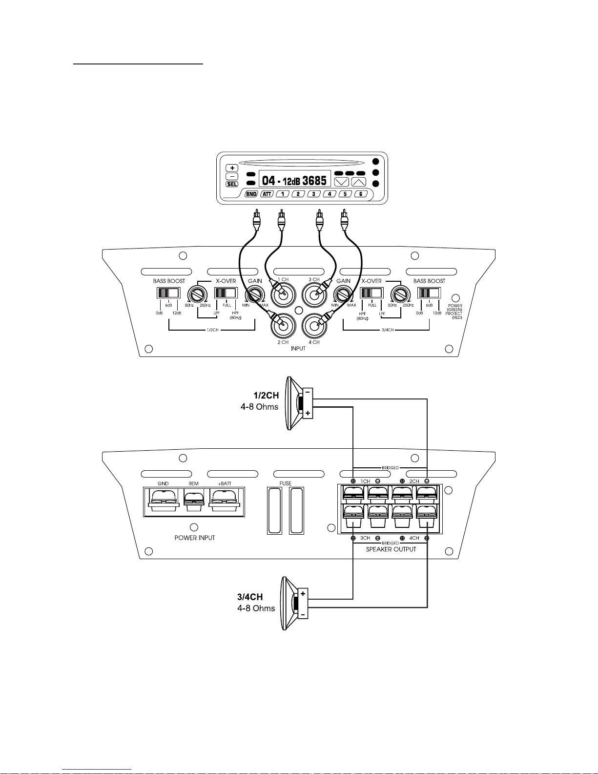
ystem Diagrams
S
4Channel S
HT
G447
ystem Design #2
Page 13
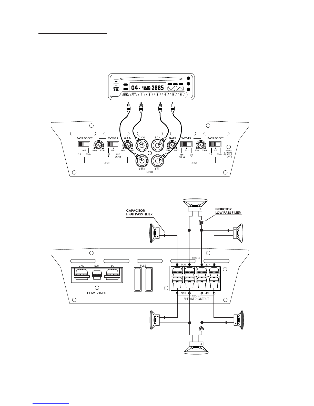
ystem Diagrams
S
4Channel S
HT
G447
ystem Design #3
WOOFER
4-8ohms
1CH
4-8 Ohms
3CH
4-8 Ohms
WOOFER
4-8ohms
2CH
4-8 Ohms
4CH
4-8 Ohms
Page 14

TROUBLE SHOO
TING GUIDE
SYMPT
NO SOUND Is the power
SWITCHING
NO SOUND
OMS CHECK POINTS CURE
LED illuminated?
No power to power wire Repair power wire or connections
AMP NOT
ON
IN ONE
CHANNEL
AMP
TURNING
OFF
MEDIUM/
HIGH
VOLUME
No power to remote
wire with receiver on
Fuse broken Check fuse
Check speaker leads Inspect for short circuit or an
Check audio input
leads
Check speaker load
impedance
Check fuses in amplifier.
Be sure Turn-on lead is connected
Check connections to radio
open connection.
Reverse Left and Right
RCA inputs to determine if it is
occurring before the amp.
Check Tuner/Deck volume level.
Clean contacts on fuse holders.
Be sure proper speakers are used
to ensure impedance
recommendations are observed.
(If you use an Ohmmeter to
check speaker resistance,
please remember that DC
resistance and AC impedance
may not be the same.)
Page 15

ARNINGS
W
Inv
estigate the layout of your automobile thoroughly before drilling or cutting any
holes. Take care when to work near the gas tanks, lines, or hydraulic lines, and electrical
wiring. Don't use power amplifier unmounted. Attach this system securely to the auto-
mobile to prevent damage, particularly in the event of an accident. Don't mount this
system so that the wire connections are unprotected or are subject to pinching or damage from nearby objects. The +12V DC power wire must be fused at the battery positive
terminal connection. Before making or breaking power connections
at this system power terminals, disconnect the +12V wire at the battery end.
Confirm your radio/cassette player and/or other equip is turned off while connecting the
input jacks and speaker terminals. If you need to replace the power fuse, replace it only
with a fuse identical to that supplied with the system. Using a fuse of different type or
rating may result in damage to this system which isn't covered by the warranty.
Page 16
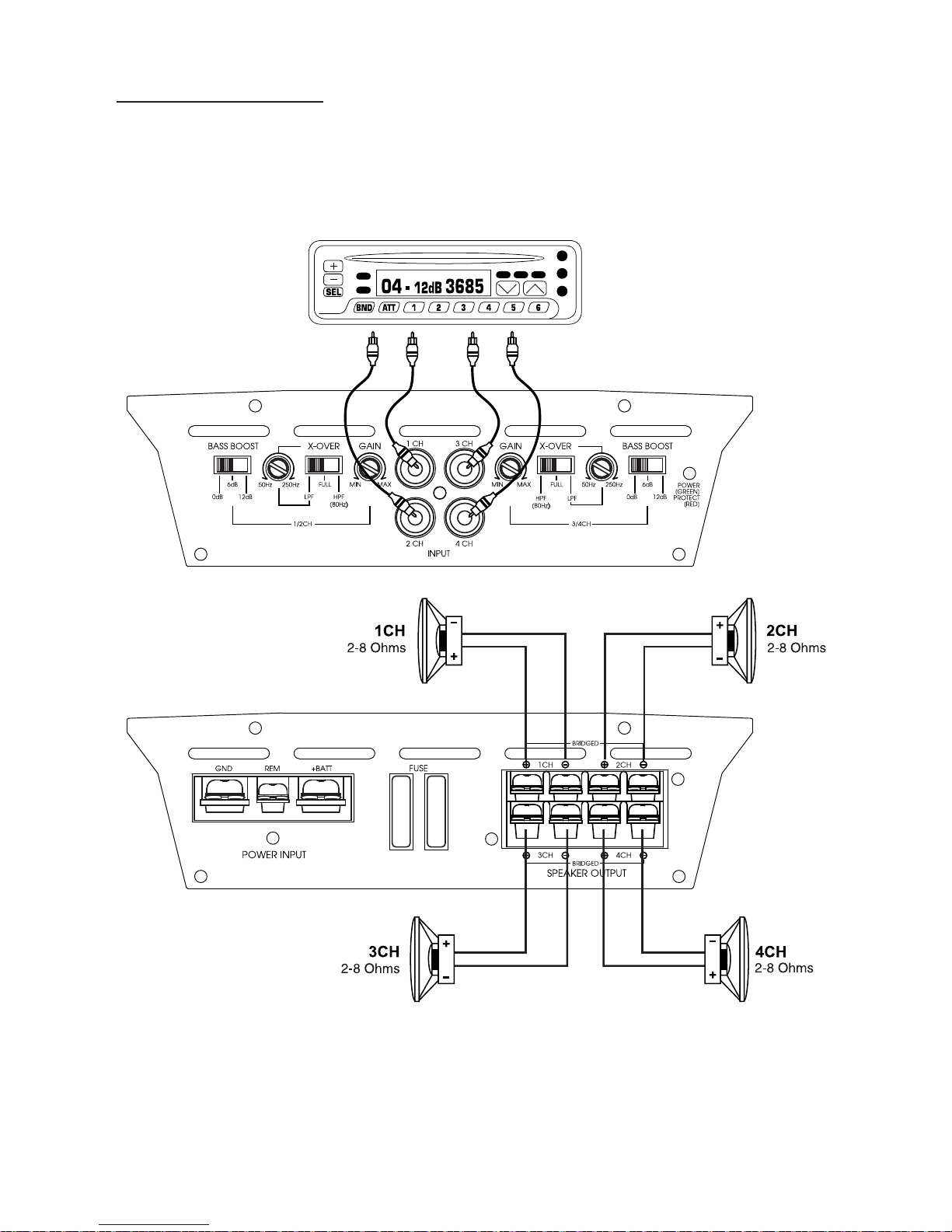
ystem Diagrams
S
4Channel S
HT
G447
ystem Design #1
Page 17
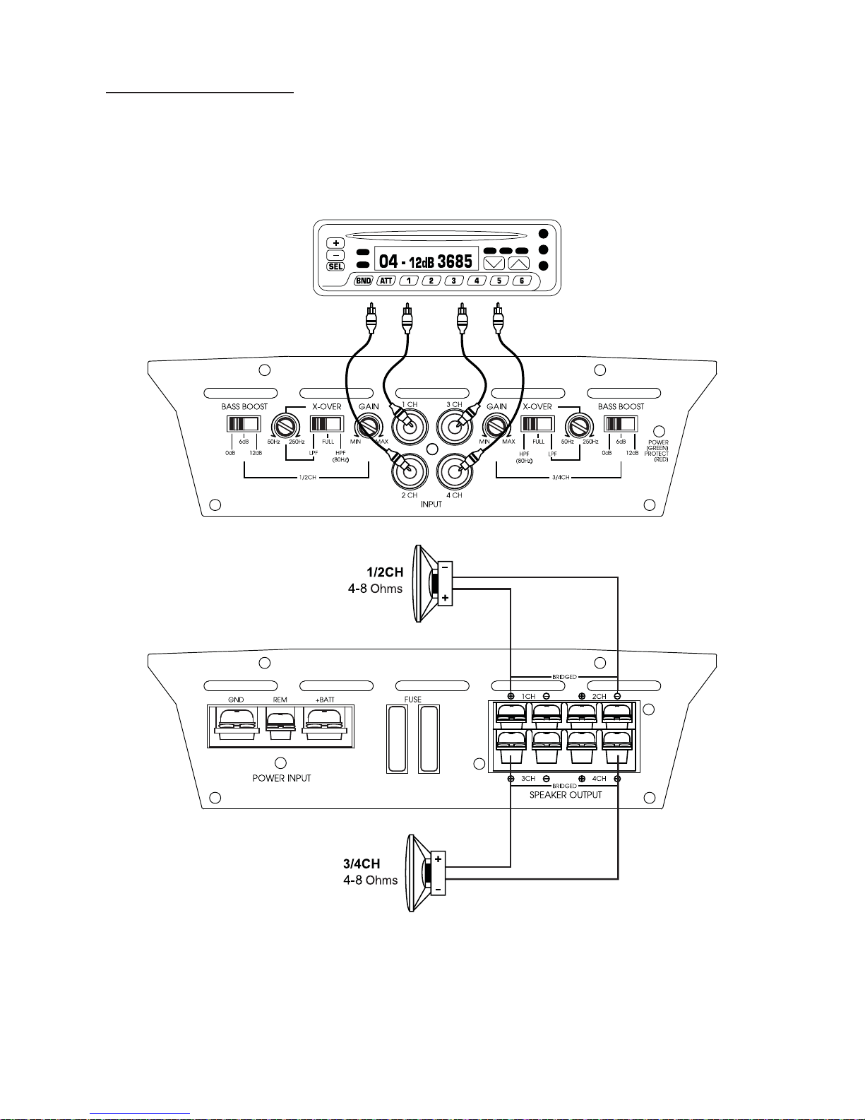
ystem Diagrams
S
4Channel S
HT
G447
ystem Design #2
Page 18
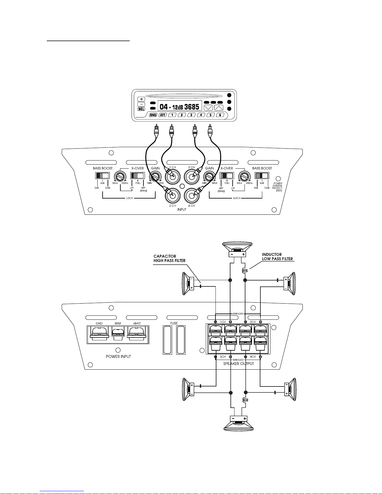
ystem Diagrams
S
4Channel S
HT
G447
ystem Design #3
WOOFER
4-8ohms
1CH
4-8 Ohms
3CH
4-8 Ohms
WOOFER
4-8ohms
2CH
4-8 Ohms
4CH
4-8 Ohms
Page 19

TROUBLE SHOO
TING GUIDE
SYMPT
NO SOUND Is the power
SWITCHING
NO SOUND
OMS CHECK POINTS CURE
LED illuminated?
No power to power wire Repair power wire or connections
AMP NOT
ON
IN ONE
CHANNEL
AMP
TURNING
OFF
MEDIUM/
HIGH
VOLUME
No power to remote
wire with receiver on
Fuse broken Check fuse
Check speaker leads Inspect for short circuit or an
Check audio input
leads
Check speaker load
impedance
Check fuses in amplifier.
Be sure Turn-on lead is connected
Check connections to radio
open connection.
Reverse Left and Right
RCA inputs to determine if it is
occurring before the amp.
Check Tuner/Deck volume level.
Clean contacts on fuse holders.
Be sure proper speakers are used
to ensure impedance
recommendations are observed.
(If you use an Ohmmeter to
check speaker resistance,
please remember that DC
resistance and AC impedance
may not be the same.)
Page 20
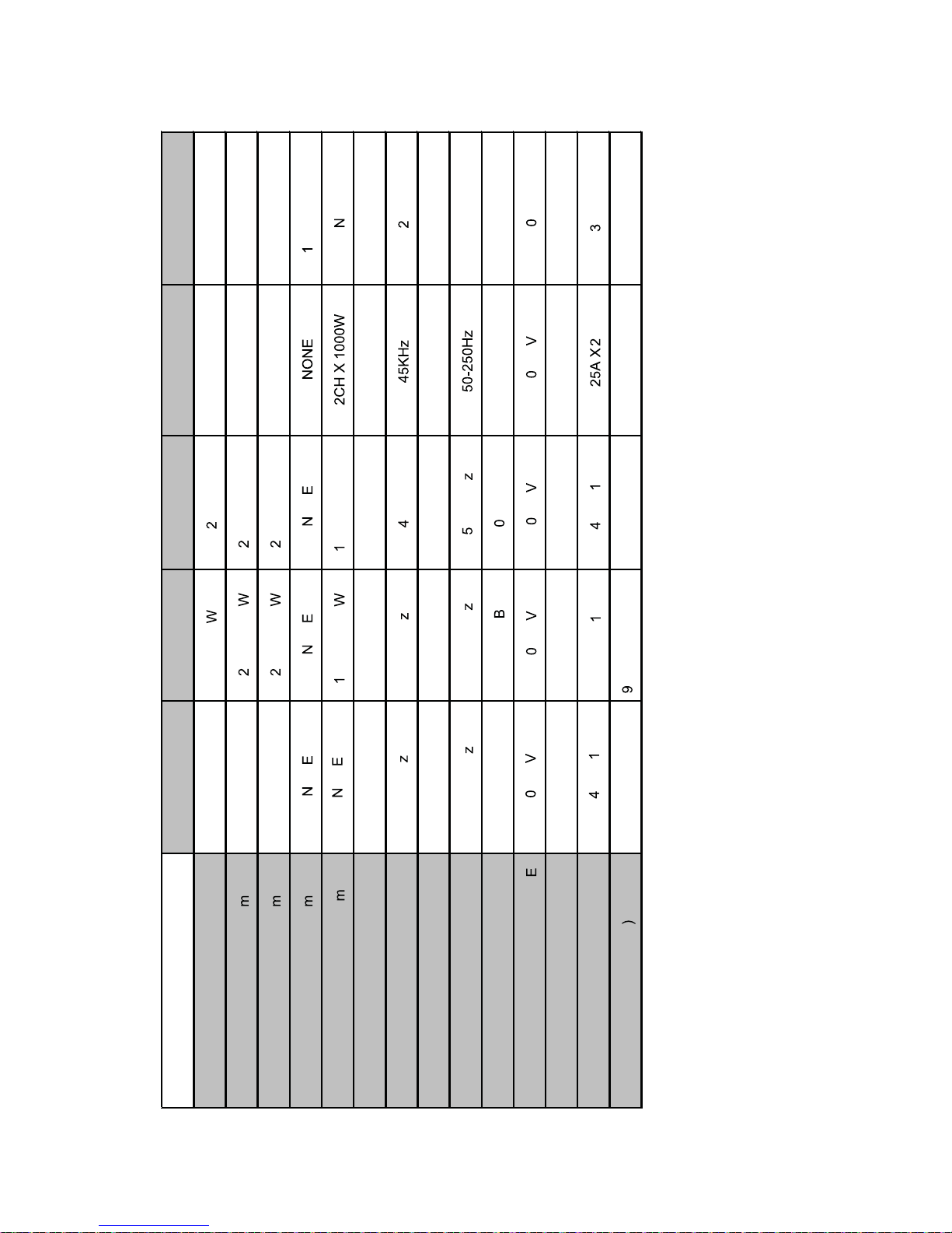
SPECIFICA
TIONS
2000W 2400W
1200W
ONE
3
0A x
0, 6, 12dB (selectable) 0-12dB
000W
HTG257 HTG447 HTG2100D
HTG237
2000W
HTG157
500W 4CH X 250W 1CH X 350W
CH X
125
CH X
1000W
1CH X
650W 4CH X 350W 1CH X 800W
CH X
225
CH X
1CH X 1500W
ON ON CH X
ON
2000W
CH X
1000
CH X
ON
5KHz 50Hz
0D.001.0 01.0 01.01
0.01
45KH
-12dB
0-250H 50-250Hz(12dB, 24dB)
8F0H8z0H 8z0H NzONE
80Hz
50-250H
.2-6 .2-6 .2-6 .2-6V
0)-12d
.2-6
12dB (selectable)
0, 6,
20K
0A X
0A X
8.81 X 2.24 12.99 X 8.81 X 2.24 14.96 X 8.81 X 2.24 14.96 X 8.81 X 2.24
.84 X
8.81 X 2.24
12.99 X
POWER OUTPUT RMS @4Oh
MAXIMUM POWER OUTPUT 1000
POWER OUTPUT RMS @2Oh
POWER OUTPUT RMS @1Oh
BRIDGED POWER MAX @4Oh
TH
FREQUENCY RESPONSE -3.0dB 45KH
T IMPEDANCE(LOW LEVEL) 20K 20 2K0K20K
HP
LP 5F0-250H
ADJUSTABLE SENSITIVITY RANG
BASS BOOST(50Hz
INPU
FUSE 25A X
DIMENSION(D x W x H inch
Page 21

ARNINGS
W
Inv
estigate the layout of your automobile thoroughly before drilling or cutting any
holes. Take care when to work near the gas tanks, lines, or hydraulic lines, and electrical
wiring. Don't use power amplifier unmounted. Attach this system securely to the auto-
mobile to prevent damage, particularly in the event of an accident. Don't mount this
system so that the wire connections are unprotected or are subject to pinching or damage from nearby objects. The +12V DC power wire must be fused at the battery positive
terminal connection. Before making or breaking power connections
at this system power terminals, disconnect the +12V wire at the battery end.
Confirm your radio/cassette player and/or other equip is turned off while connecting the
input jacks and speaker terminals. If you need to replace the power fuse, replace it only
with a fuse identical to that supplied with the system. Using a fuse of different type or
rating may result in damage to this system which isn't covered by the warranty.
LANZAR SPEAKERS
SPEAKER SYSTEM
 Loading...