

Heritage HM-560B Installation And Service Instructions Manual

Heritage MedCall
Sentry E-Call
Model HM-560B
Photoelectric
Smoke Detector
Issue 1, March 2005430-560B 0305 ©Heritage MedCall, Inc.
Heritage Medcall Sentry Emergency Call System
PRINCIPLE OF OPERA TION
The Model HM-560 Smoke Detector is a conventional
4-wire 12 VDC photoelectric smoke detector. This
technology is superior in reliability and performance to
less expensive ionization type smoke detectors. A
high intensity infrared light emitting diode (LED) light
source is pulsed in a sensing chamber that is designed for optimum smoke entry . The light source
LED and a photo-diode sensor are positioned in the
chamber at angles to each other so that when no
smoke is in the chamber, the sensor sees virtually no
light.
Light scattered by smoke particles in the chamber is
sensed by the photo-diode. When the light reaching
the photo-diode reaches a predetermined level, the
detector will sound an alarm. Once the smoke has
been cleared from the unit, it is reset by pushing the
Check-In button on the apartment Host Panel.
Because smoke may have to travel some distance
from the fire source to the detector, it is import ant that
the photoelectric detector responds best to both open
flame and smoldering fires.
Model 560B Smoke Detector
Installation and Service Instructions
The HM-560B Smoke Detector includes automatic
sensitivity testing. Once daily and upon power-up the
detector performs a full diagnostic test that includes a
dynamic test of the sensing chamber and internal
electronics. This meets NFPA 72 field sensitivity
testing requirements without the need for external
meters.
The detector also contains an integral piezoelectric
horn which produces an interrupted 85 dBa T emporal
3 tone.
WHERE TO LOCA TE
The smoke alarm should be installed in accordance
with National Fire Protection Association (NFP A)
St andard 72. Excerpts follow:
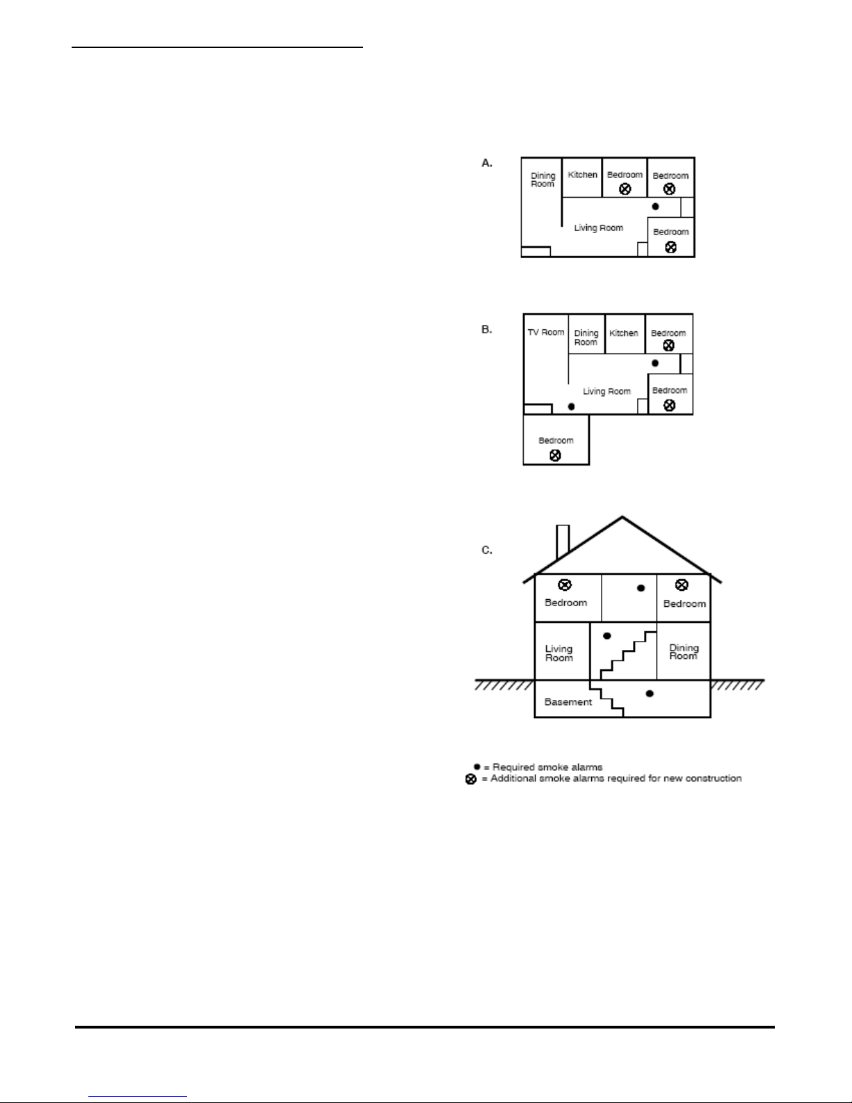
A-8-1.2.1a Where to Locate the Required Smoke
Alarms in Existing Construction
The major threat from fire in a family living unit occurs
at night when everyone is asleep. The principal threat
to persons in sleeping areas comes from fires in the
remainder of the unit. Therefore, a smoke detector(s)
is best located between the bedroom areas and the
rest of the unit. In units with only one bedroom area
on one floor, the smoke detector(s) should be located
as shown in Figure 1A.
FIGURE 1 DETECTOR LOCATION
In family living units with more than one bedroom area
or with bedrooms on more than one floor, more than
one smoke detector is required, as shown in Figure
1B.
In addition to smoke alarms outside of the sleeping
areas, the installation of a smoke alarm on each
additional story of the family living unit, including the
basement, is required. These installations are shown
in Figure 1C. The living area smoke alarm should be
installed in the living room or near the stairway to the
460-560B 0305 ©Heritage MedCall, Inc.
Page 1
Issue 1, March 2005
Heritage Medcall Sentry Emergency Call System
Model 560B Smoke Detector
Installation and Service Instructions
upper level, or in both locations. The basement
smoke alarm should be installed in close proximity to
the stairway leading to the floor above. Where
installed on an open-joisted ceiling, the alarm should
be placed on the bottom of the joists. The alarm
should be positioned relative to the stairway to
intercept smoke coming from a fire in the basement
before the smoke enters the stairway .
Where to Locate the Required Smoke Alarms in
Existing Construction
All of the smoke alarms specified for existing construction are required and, in addition, a smoke alarm
is required in each bedroom.
Are More Smoke Alarms Desirable?
The required number of smoke alarms might not
provide reliable early warning protection for those
areas separated by a door from the areas protected
by the required smoke alarms. For this reason, it is
recommended that the (designer/installer) consider
the use of additional smoke alarms for those areas for
increased protection. The additional areas include the
basement, bedrooms, dining room, furnace room,
utility room, and hallways not protected by the
required smoke alarms. The installation of smoke
alarms in kitchens, attics (finished or unfinished), or
garages is not normally recommended, as these
locations occasionally experience conditions that can
result in improper operation.
height, high air movement, and other conditions or
response requirements.
Locate in a suitable environment:
-T emperature between 32°F (0°C) and 100°F (38°C)
-Humidity between 0 and 95% non-condensing
Locate away from air conditioners, heating registers
and any other ventilating source that may interfere
with smoke entering the detector. Locate away from
kitchens, wood stoves, garages, furnaces and
bathrooms.
Mount smoke detectors on a firm permanent surface,
typically a stud or metal runner .
Additional information on Household Fire Warning is
available at nominal cost from: The National Fire
Protection Association, 1 Batterymarch Park, Quincy,
MA 02169-7471 or www .nfp a.org. Request the latest
Standard No. NFP A 72.
IMPORTANT!
REGULATIONS PERTAINING TO SMOKE
DETECTOR INSTALLATIONS VARY FROM STATE
TO STATE. FOR MORE INFORMATION, CONTACT
YOUR LOCAL FIRE DEPARTMENT OR LOCAL
AUTHORITY HAVING JURISDICTION.
In addition to NFP A 72, use the following location
guidelines to optimize performance and reduce the
chance of false alarms.
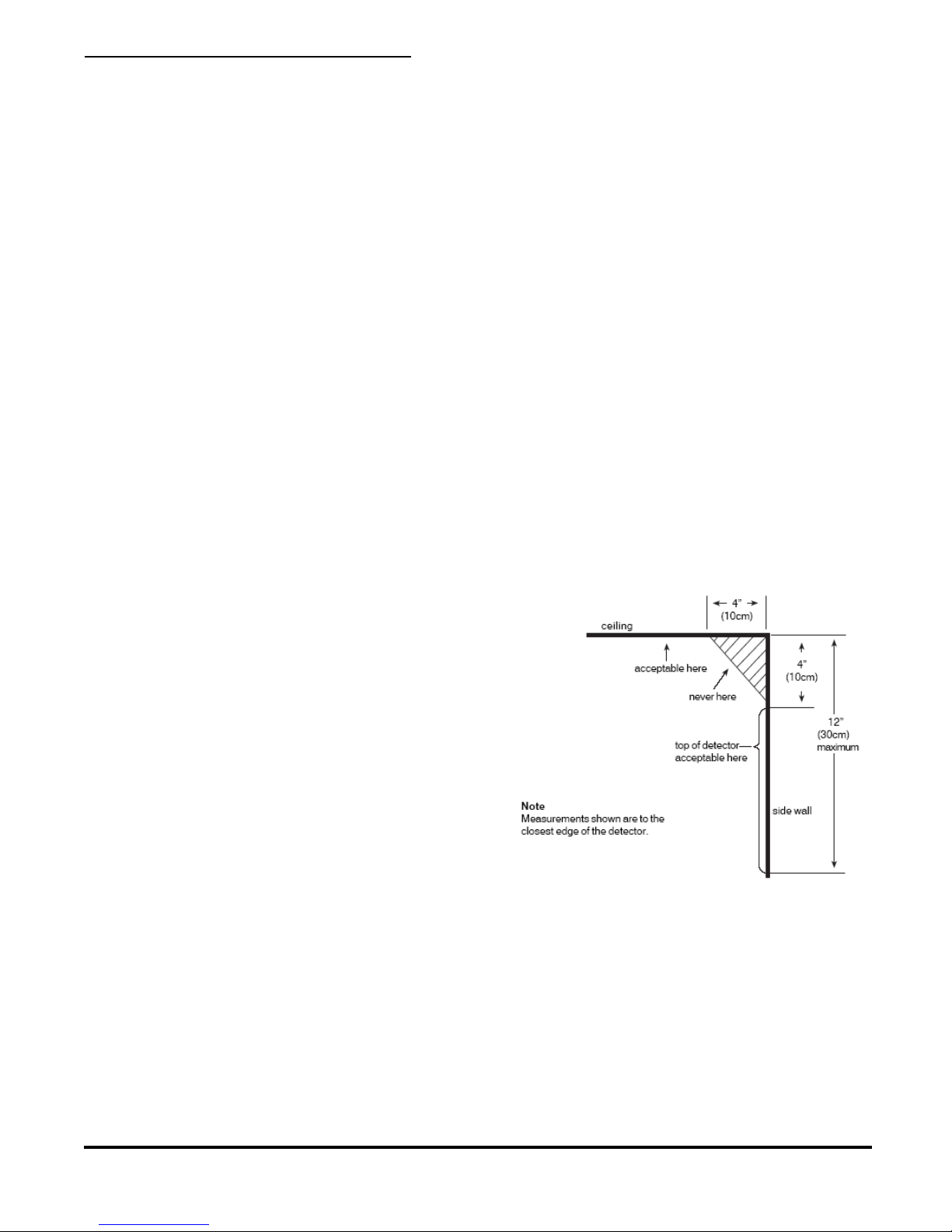
Locate ceiling mounted smoke detectors in the center
of a room or hallway at least 4 inches from any walls
or partitions.
Locate wall mounted smoke detectors so the top of
the alarm is 4 to 12 inches below the ceiling.
When more than one detector is required, spacing of
30 feet may be used as a guide on smooth ceilings.
Other spacing may be used depending on ceiling
430-560B 0305 ©Heritage MedCall, Inc. Issue 1, March 2005
PENDANT RECEIVER OPTION
The Model HM-547 Pendant Receiver is sometimes
used in apartment installations to receive a call signal
from a handheld wireless pendant. The location of a
smoke detector towards the center of the living area
within an apartment makes a good location to install
Page 2
FIGURE 2 DETECTOR PLACEMENT
 Loading...