

hergom Harmony 25, Stanford 25, Stanford 35, Harmony 35 Operating And Installation Instruction
Page 1

Pag.1
OPERATING AND
INSTALLATION INSTRUCTION
STANFORD / HARMONY 25
STANFORD / HARMONY 35
UNITED KINGDOM-UK IRELAND-IE
Page 2

Pag.2
GENERAL NOTES
1. USER INSTRUCTIONS Page. 3
1.1 General
1.2 Manual transmitter
1.3 Screen setup
1.4 Setting the time
1.5 Setting the timer
1.6 Operation
1.7 Possible error messages
1.8 Setting the flame height
1.9 Switching the unit off
1:10 Inserting and replacing the batteries
1.11 Igniting the fire
1.12 Extinguishing the fire
1.13 Switching the unit off
2. INSTALLATION INSTRUCTIONS Page. 7
2.1 General instructions
3. PLACING THE APPLIANCE Page. 8
3.1 Connection the gas lines
3.2 Preparation and installation
3.3 Fitting the ceramic logs
4. TECHNICAL DETAILS GV60 Page. 9
5. INSTRUCTIONS FOR MERTIK MAXITROL GV60 GASCONTROL Page. 10
6. GAS TECHNICAL DATA Page. 11
7. CONCENTRIC CHIMNEY LAY OUT Page. 12
8. CONCENTRIC FLUE SYSTEM PagE. 13
8.1 Components of the concentric flue system
8.2 Construction of concentric flue system
8.3 Installation instructions regarding existing flues
8.4 Components
8.5 Installation
8.6 Cleaning and maintenance
9. TROUBLESHOOTING LIST MERTIK GV60 Page. 16
10. PROBLEMS AND POSSIBLE SOLUTIONS Page. 19
APPENDIX 1 DIMENSIONAL DRAWINGS
APPENDIX 2 INSTALLATION EXAMPLES
APPENDIX 3 FITTING LOG SET
ALL RIGHTS RESERVED.
(5/23122016)
Page 3
Pag.3
REMOTE CONTROL
1.1 General
* The unit is operated using a radio-controlled remote control. This consists of a manual transmitter
and a receiver. The receiver is connected to the gas control block.
* The receiver and the gas control block are located in the operating box.
* If there is no change in flame height for a 6-houre period the transmission / communication turn
down application will turn down the pilot flame.
* If there is no change in flame height for a 5-days period the appliance will be turn down.
* Appliance will be turn off if there is no change in flame height for 5 days.
* Low battery receiver shut off; If power is low in receiver the systems shuts off the fire completely.
* When in use with 220V adapter and the power shuts off, the batteries will take over the power
supply to let the receiver automatic function normally.
* Designated low and high fire settings;
Double click the small flame button and the flame will be automatically go to low flame.
Double click the large flame button and the flame will be automatically go to high flame.
1.2 Manual transmitter
* The transmitter uses a radio-controlled signal. The signal code is set at the factory
1.3 Screen setup
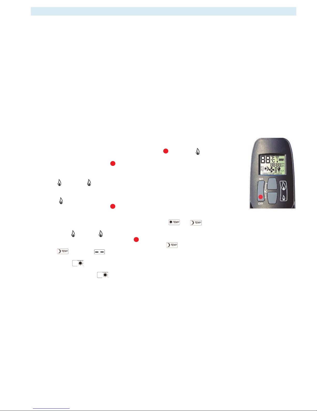
* After the batteries have been inserted, press the OFF button and (small) at
the same time to toggle between °F (and 12 hour clock) and °C (and 24 hour clock).
* Wait a moment or press OFF to return to MAN mode.
1.4 Setting the time
* Press (large) and (small) at the same time to go to the SET mode or
programming mode.
* The time can be set while the screen is flashing.
* Press (large) to set the hour and minutes.
* Wait a moment or press OFF to return to MAN mode.
1.5 Setting the timer: P1 and P2 ( ONLY THERMOSTAT VERSION)
* Briefly press the SET button to select the required mode or
* Keep the SET button pressed until the screen starts flashing.
* Then press (large) or (small) to set the required temperature.
* Wait a moment or briefly press the OFF button to select the MAN mode.
* If the temperature setting also needs to be switched off (to reduce battery use),
* Turn down until appears on the screen.
* Once the temperatures have been set, the programme can be set by pressing the SET button.
Programme will appear. Keep the SET button pressed to set the time for the first on and
off programme. Set the time you want the unit to switch on. Then press the SET button to switch the unit off.
* Press SET again for the programme.
Set the time you want the unit to switch on. Then press the SET button to switch the unit off.
* Press SET again to see the current programme on the display.
1. USER INSTRUCTIONS
Remote control
P1
P2
Page 4
Pag.4
1.6 Operation (Remote Control)
Igniting the flame
* Open the gas shut-off cock that has been installed in the gas pipe to the unit.
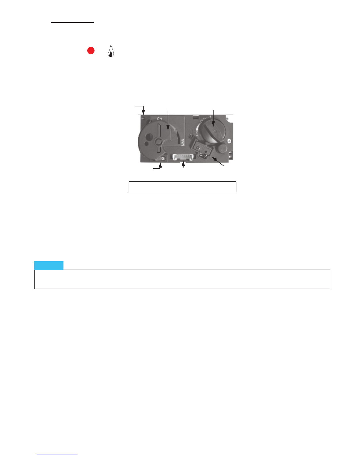
* Press the “O I” switch on the gas control block to the “I” position.
* Turn the operating button on the gas control block into the ON position.
* Press the OFF and (large) switches on the remote control at the same time. A short sound signal will con-
firm commencement.
Short sound signals will then follow until the pilot light and main burner are ignited.
Once the main burner is ignited, the flame will adjust to its maximum height automatically.
1.7 Possible error messages
* Long sound signals during ignition: Receiver batteries are almost empty. (After this signal is heard, the unit may be
switched on approximately 10x more).
* 5 seconds of continuous sound signal: Error message. For example: one of the cables is not connected, the “O I”
switch is not in the “I” position.
* 5x short sound signal: The pilot light or main burner are not ignited.
Possible cause: air in the pilot pipes.
Piëzo Ignitter
(Manual)
Manual knob
Main valve knob
Microswitch
“O I” Switch
8 Wire Receiver Jack
Combination Control, Cover
If the pilot light is extinguished, wait at least 5 minutes before
repeating the steps above.
NOTICE
Page 5

Pag.5
1.8 Setting the flame height / extinguishing the flame
* After the burner is ignited, the flame size will adjust to its maximum height automatically.
* Press the button (small) on the image of the flame to reduce the height and to switch the burner off.
(Extinguishing the flame: “STAND BY”). (Press the key for a short time to gradually reduce the flame.)
* Press the (large) button to increase the flame height. (Press the button briefly to gradually increase
the flame height)
1.9 Switching the unit off.
* Press the (small) button to reduce the flame height and to switch the burner off (“STAND BY”).
* Then press OFF to switch off the entire unit, including the pilot light.
* If the unit is out of use for a long period, set the “O I” switch on the gas control block to
the “O” position to save the batteries.
* In this case, it is also recommended you close the gas shut-off cock in the supply line.
Breakdowns:
* If the receiver is not receiving signals from the manual transmitter effectively, this could be caused by:
1. Flat batteries: replace the batteries.
2. An electronic problem: press “RESET” on the receiver.
3. Contact your fitter if the unit switched off regularly.
1.10 Inserting and replacing the batteries
* The manual transmitter and receiver batteries have a life span of approximately one year.
The use of alkaline batteries is recommended.
* The batteries need to be replaced when:
1. Manual transmitter: BATT appears on the display.
2. Receiver: long sound signals can be heard during ignition.
1. Manual transmitter:
* Open the small cover on the back.
* Carefully remove the 9V square battery and remove the battery from the contact holder.
Do not pull the wires!
* Connect the new battery and place the whole unit back. Close the cover.
2. Receiver:
* Carefully remove the entire receiver from the holder.
* Slide the small cover open.
* Remove the batteries from the battery holder.
* Place 4 new 1.5V batteries (type LR6 or AA) in the battery holder as shown. The spring must always be
against the negative (-) pole of the battery.
* Close the cover and place the receiver back into the holder.
If the batteries are not inserted correctly, the electronics of drive mechanism could be damaged irreparably.
Replace the batteries only when the unit is completely switched off.
Use only
non-metallic
tools to remove the batteries .
Removing batteries with a metal object may cause permanent damage to the electronic control.
NOTICE
If, for whatever reason, the pilot light goes out, you must wait 5 minutes before reigniting it.
NOTICE
Page 6
Pag.6
MANUAL CONTROL (In case of emergency, only applies to non remote control function)
The unit may be operated by hand if there is a defect in the remote control. To do so, the ignite (piezo) cable
of the receiver must first be removed and carefully slid into the piezo connector on the gas control block.
1.11 Igniting the fire
* Open the gas shut-off cock that has been installed in the gas pipe to the unit.
* Press the “O I” switch, on the gas control block, in the “I” position.
* Turn the motor button, on the gas control block, completely to the right.
The button will make a "click” sound.
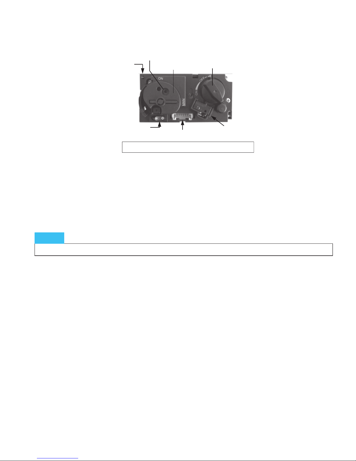
* Turn the operating button on the gas control block, into the “MAN” position.
A metal circle in the operating button will become visible.
* Push the metal circle inwards. For example, with a pen. Gas will now flow to the pilot flame.
* While keeping the metal circle pressed down, press the (square) piezo button
(along the “O I” switch) several times to ignite the pilot flame. You will be able to see whether
the pilot flame is burning through the glass window.
* If the pilot flame is alight, keep the metal circle pressed down for another 10 seconds and then let go.
* Turn the operating button to the ON position. The burner may or may not ignite, depending on the
position of the motor button.
* By turning the motor button to the required setting to the left, the burner will ignite and the
flame size can be adjusted.
1.12 Extinguishing the fire
Turn the motor button, on the gas control block, completely to the right. The button will make a "click” sound.
The burner will turn off. The pilot flame continues to burn.
1.13 Switching the unit off
Press the "O I” switch, on the gas control block, in the “O” position. The pilot flame will extinguish.
If the fireplace is not used for an extended period of time, we recommend closing the gas shut-off cock
in the supply line.
Piëzo Knop
Piëzo Ignitter
(Manual)
Manual knob
Main valve knob
Microswitch
“O I” Switch
8 Wire Receiver
Small metal circle for
Manual ignition
(Combination Control, Cover Manual position)
If, for whatever reason, the pilot light goes out, you must wait 5 minutes before reigniting it.
NOTICE
Page 7

Pag.7
2.1 General instructions
* The gas fireplace must be installed, connected and inspected as a balanced flue fire by a qualified fitter,
according to national, regional, and local standards and regulations.
* The flue system and the terminals in the outer wall or roof face must also meet the requirements
outlined in the applicable standards and regulations.
* The temperature of the walls and shelves near the side and back of the unit may not be more
than 80°C higher than the temperature of the environment.
* The unit has been approved in combination with the THC CC Ø100 mm - Ø150 mm and
Ø130 mm - Ø200 mm , in accordance with European CE standards for gas fires, and may therefore
only be applied with this system.
* The product needs to be serviced and inspected by the fitter for local gas distribution as indicated on
the identification plate.
* The instructions are only applicable if the relevant country code is stated on the unit. If this is not the
case, the gas technical information for the relevant country needs to be consulted and modifications
discussed with the manufacturer.
* There will be air in the gas pipes when the unit is first used. The gas pipes therefore need to be purged first.
* Ignite the fire according to operating instructions and check whether the burner flame is uniform.
After the unit has been used for the first time, you should remove any deposits resulting from
Running/burning in the paint, using a glass cleaner for heaters.
Distance to flammable materials:
* With respect to the front, side and top of the unit, a distance of 1200 mm needs to be kept between
the unit and: curtains, floor covering, upholstery and fabrics, and/or other flammable material unless
stated other wise in these instructions.
Distance to non-flammable materials:
* The unit needs to be placed a minimum distance of 25 mm from the wall unless stated otherwise in
these instructions.
The installation should be performed only by an authorized gasfitter
NOTICE
2. INSTALLATION INSTRUCTIONS
WARNING
Gas fires become hot when they are in operation. After installing the appliance the glass surface
is considered active zone. The glass surface can become very hot.!
Attention! Accordingly, care should be taken, for example children and needy in the vicinity of
burning fires are banned. Gas fires must not be on or against flammable materials are placed
(curtains etc.).
Never install the unit against or within a flammable wall!.
Construction material for fireplaces and mantles etc. or built-in situation, must be made of
non-combustible material. This also applies to floors and ceilings. Never use flammable
materials near the unit in compliance with the above requirements.
If in doubt, consult your dealer
NOTICE
Page 8
Pag.8
3.1 Connection the gas lines
You can determine where the gas pipes will be placed, depending on the positioning of the appliance.
Ensure control equipment is not twisted during installation and there is no excessive tension.
Accessibility of various connection points in relation to components need to be maintained.
After installation, check the connections for gas leakage. Use a 3/8“ gas tap in the main gas supply.
Ensure the gas pipes are dirt-and sand-free. The gas connection should only be done without
any excessive tension in the tubes etc. This prevents any damage occurring to the gas control equipment.
3.2 Preparation and installation
* Open the door.
* Remove the packaging and check the unit for possible damage.
* Please note: place the unit on a stable surface.
* Do not place the unit on its back/side!
* Place the unit at the installation location
* Take all the packaged components out of the unit and check to make sure they are not
damaged or broken.
* Situate the unit (see Appendix 2 as an example of an installation location) in your chosen
installation location.
* The adjustable feet allow to adjust the device more refined.
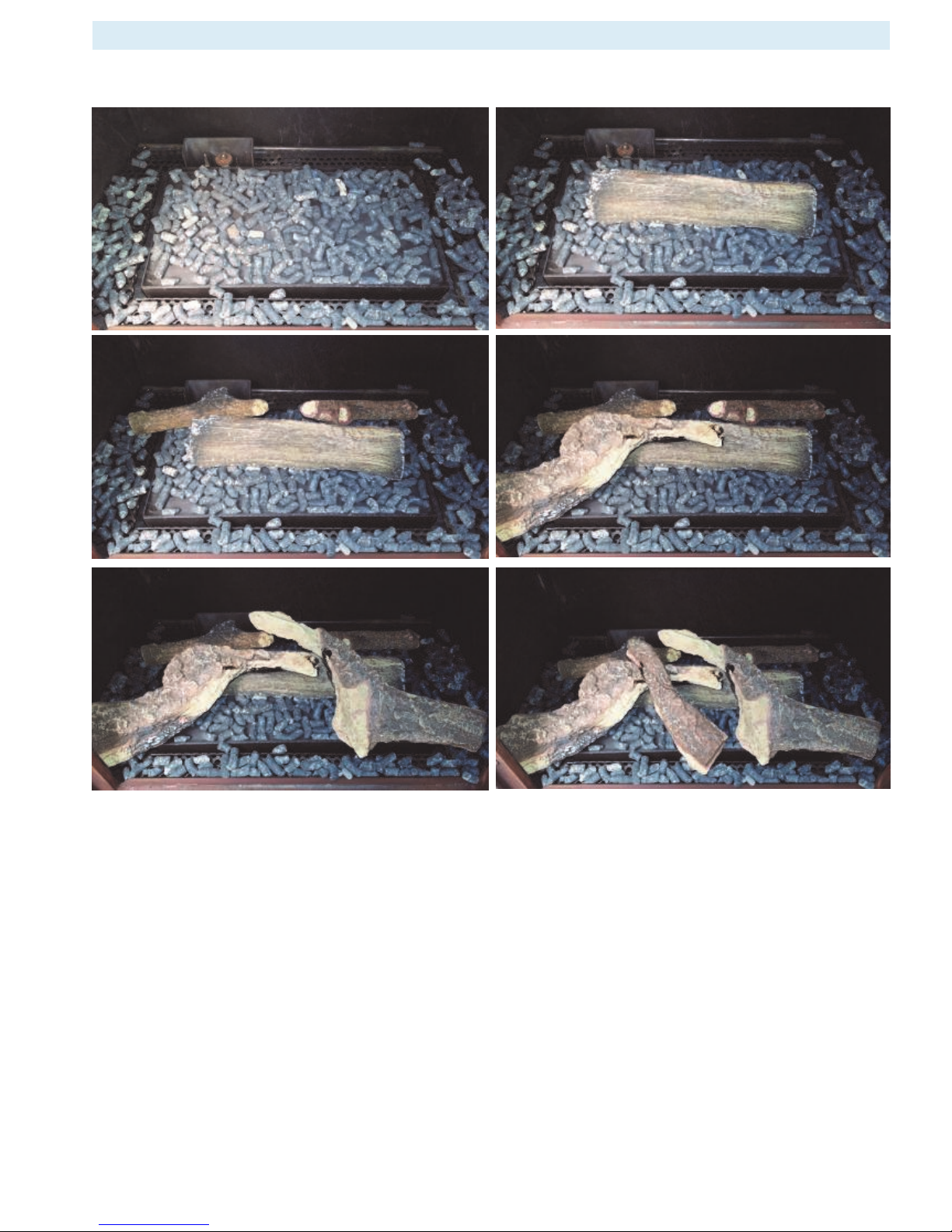
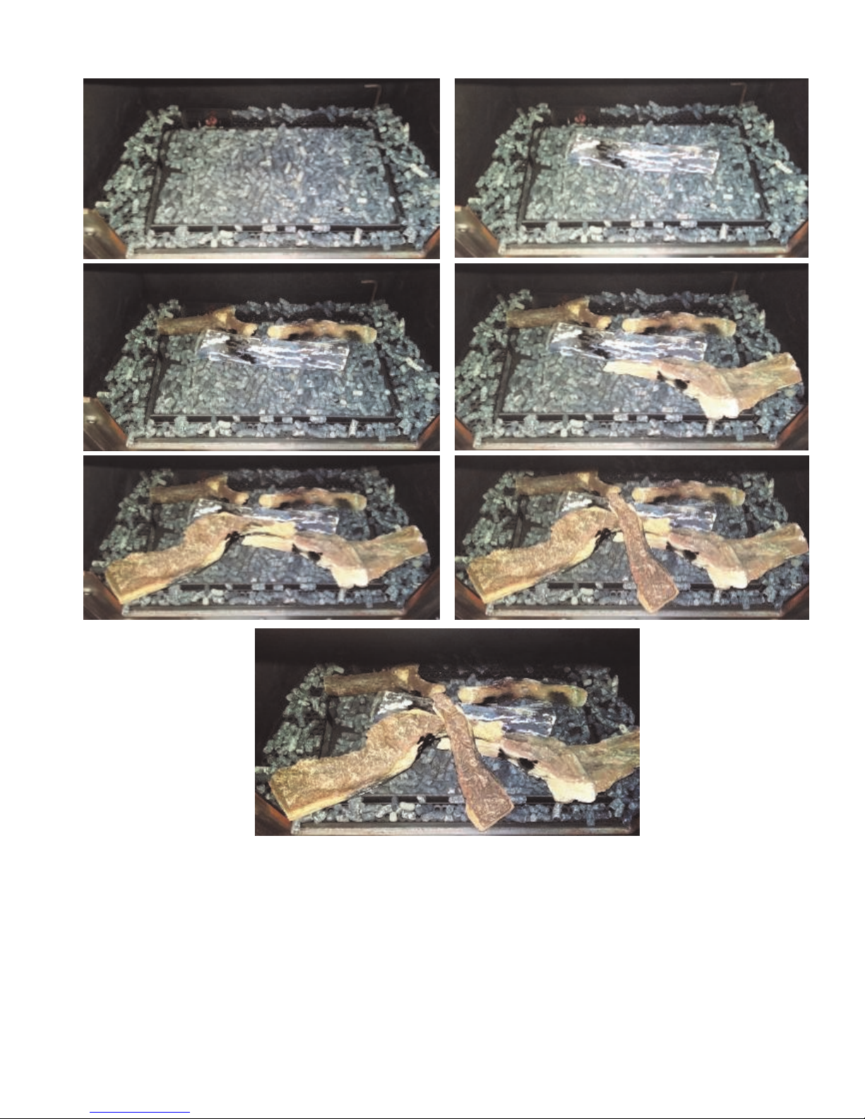
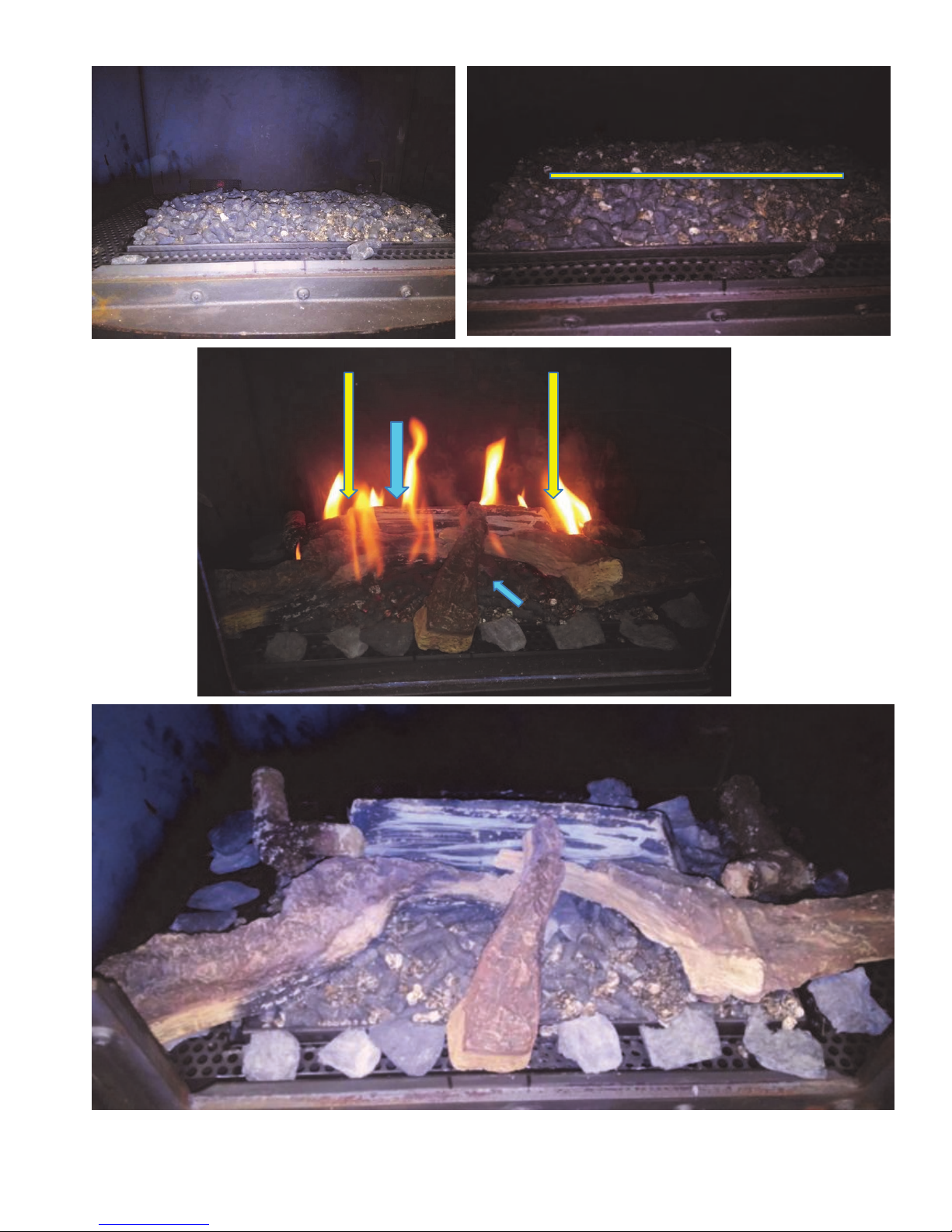
3.3 Fitting the ceramic log inset (see Appendix 3)
Method:
* Spread the glowing material (lava granules) evenly over the burner and the burner decoration plate
so that they are just covered. Glowing embers can be placed here and there as decoration.
* Place the ceramic wood blocks in the correct order as shown on Appendix 3.
* Place the logs carefully. Other location can seriously affect the flames or malfunction of the
burn process (sooting)
* Slot/opening between burner and mesh deco plate must be kept free of glowing material.
* Before closing the door make sure if there must be a restriction plate to be placed or not.
See chapter 7 "Concentric chimney lay out"
* If there is a restriction required for your situation, remove the baffle plate by unscrewing it
from the front of the plate and move the plate backwards and then out. Now install the restriction
plate with two screws and replace the baffle plate.
* Close the door.
NOTICE
Before installing the device it is recommended to first read Chapter 7
"Concentric flue system"
to consult.
3. PLACING THE APPLIANCE
Notice
MAKE SURE THE PILOT LIGHT REMAINS UNOBSTRUCTED!
Note: when installing the log set and the various glowing materials and accessories, the following must
be taken into account:
A: No glowing material in or on the pilot burner.
B: Prevent that ceramic material falls on the glass seals. Remove this if necessary. The window can be damaged.
C:
Slot /opening between burner and mesh deco plate must be kept free of glowing material. Too
much placed glowing material can affect the combustion process.
Page 9
Pag.9
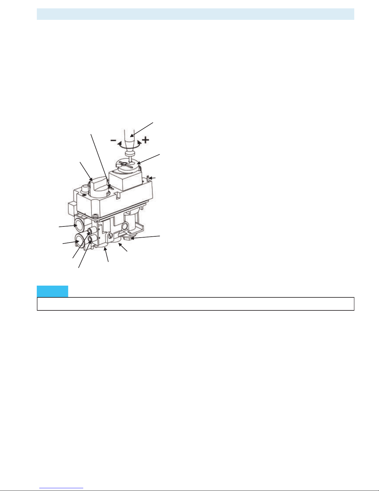
Gas valve type : Mertik GV60
Ignition : Afstand bediening en Piëzo ontsteking
Gas connection : 3/8 “ (Internally)
Pilot flame : SIT 3 flames
Unit category : C11-C31-C91
Combustion gas discharge
and Combustion air supply : Concentric: Ø100/ 150 mm
4. TECHNICAL DETAILS GV60
Main valve knob
Thermocouple
connection
Pressure regulator
Ignition connection
Pilot gas adjustment
MAN knob
Side inlet
Side outlet
Bottom outlet
Bottom inlet
Inlet pressure
Outlet pressure
NOTICE
SEALED PARTS MAY NOT BE ADJUSTED.
Page 10

Pag.10
Ensure that the fuel supplied to the unit is clean and free from particles and moisture.
Before a gas supply pipe (new or existing) is connected to the main gas pipe at the gas meter and to
the gas control block of the unit, clean and dry compressed air should been blown through it.
Cut copper pipes as well as aluminium pilot pipes must be deburred and blown clean before they
are connected. The dust filter at the connection to the gas control block will only filter out the
coarsest dirt from the system. Fine particles are still able to reach the inside and may damage and/or
adversely affect regulation in the gas control block .
Heat, moisture and dust are a threat to all electronic components
Protect the electronic gas control
until
all construction, plastering and paintwork has been completed.
If such work cannot be avoided, then protect the control against dirt and moisture penetration by using,
for example, plastic film .
Only place the batteries
after
wiring to the receiver, gas control block and pilot set is connected.
Premature connection to the energy source may damage the control’s CPU (central processor).
Ensure that the ignition cable is not near the antenna wire and that they do not cross each other.
The high voltage released at ignition may damage the sensitive receiver circuit.
This may mean that the unit becomes less responsive or not responsive at all to handset commands.
Extend the supplied thermocouple with just the original extension. (available from your supplier)
Unauthorized extension of the thermocouple has the effect of stress reduction, thereby
the magnetic coil can not be activated.
Prevent leakage of the ignition spark to other parts of the installation than the Ignition by the pilot
Keep the ignition free of hull or other metal parts. If cable extension is used, see to it that connections are
additionally insulated with silicone grommet.
For automatic start via the transmitter, the receiver and the control the gas control valve to
be switched
The oval disk on the gas control block should be turned to the ON position. The I/0 switch should
to be set to "I". The ignition must be connected to the receiver box at the terminal SPARK.
The transmitter's contains the thermostat sensor system
The transmitter operates best at 2 to 3 m from the unit. Although the communication via short wave radio
signals takes place, it is recommended that the transmitter in the 'visibility' of to lay the gas apparatus in
a place where the user wants to experience a pleasant temperature. Place the hand transmitter in direct
sunlight or other hot places. The thermostat measures the temperature and regulates the flame size of the
gas in accordance.
Remove batteries only with the red ribbon which is under the battery, not with metal tool
Removing batteries with a metal object, the electronic control can permanently damage.
5. INSTRUCTIONS FOR MERTIK MAXITROL GV60 GASCONTROL
Electronic components will become permanently faulty when exposed to temperatures higher than 60°C.
Standard AA batteries will crack open at temperatures >54°C and the battery contents will damage the
electronic switches located underneath. Batteries last longest at <25°C. At >50°C the life span is around
23 weeks, this makes the use of the gas fire unnecessarily expensive.
Only install the gas control block and receiver as pre-installed at the factory
Remember that components may have to be replaced or that repairs may have to be performed at a later date.
This may be more difficult if the control is installed using a method that is different from the instructions
provided here.
WARNING
IN THE EVENT OF REPLACEMENT
Do not tighten the contact breaker and the thermocouple connection too tightly on the gas control
block or to each other. It is sufficient to tighten by hand and add a half a turn with an open-end spanner.
Tightening too much will break the connection to the magnetic coil below and/or the insulation around
the aluminium contact pin in the contact breaker. This may lead to the magnetic coil not opening the gas
supply to the pilot and the unit not working.
NOTICE
WARNING
It is forbidden to start up the unit if window (s) are not present or broken!
NOTICE
Waiting time of 5 minutes between each starting attempt
Page 11

Pag.11
Appliance has NoX Class 5
AT I2H, I3B/P BE I2E+, I3+ DK I2H, I3B/P DE I2E, I3B/P
FI I2H, I3B/P FR I2E+, I3+ GR I2H, I3B/P GB I2H, I3+
IS I3B/P IE I2H, I3+ IT I2H, I3+ LU I2E, I3B/P
NL I2L, I3B/P NO I3B/P PT I2H, I3+ ES I2H, I3+
SE I2H, I3B/P CY I3B/P, I3+ EE I2H, I3B/P LT I2H, I3B/P
LV I2H, I3B/P MT I3B/P HU I2H, I3B/P PL I3B/P
SI I2H, I3B/P SK I2H TR I2H, I3B/P
6. GAS TECHNICAL DATA
Stanford/Harmony 35
Stanford/Harmony 25
GASTYPE GASTYPE G20 G25 G30//G31
CATEGORY I2H/I2E/I2E+ I2l/I2ELL I3B/P//I3+
PRIMAIRY AIR 2XØ9 1XØ9 2XØ18 + 1XØ16
PRE PRESSURE MBAR 20 Mbar 20/25Mbar 30//30-37//30 Mbar
BURNERPRESSURE HIGH MBAR 18,5 18 28,9
BURNERPRESSURE LOW MBAR 3,6 3 11
INJECTOR SIZE Ø MM 1,9 2,1 1,15
INJ. PILOTBURNER CODE 51 51 30
LOWSETTING SIZE MM 1,7 1,7 1
LOAD Hs KW 6,8 6,9 4,9
LOAD Hi KW 6,1 6,2 4,6
CONSUMPTION M³/h 0,64 0,76 0,14
NOM.OUTPUT kW 5,1 4,5 3,2
GASTYPE
G20 G25 G30//G31
CATEGORY
I2H/I2E/I2E+ I2l/I2ELL I3B/P//I3+
PRIMAIRY AIR
2XØ8 2XØ8 3XØ16
PRE PRESSURE MBAR
20 Mbar 20/25Mbar 30//30-37//30 Mbar
BURNERPRESSURE HIGH MBAR
9 14,7 28,6
BURNERPRESSURE LOW MBAR
1,5 2,1 14
INJECTOR SIZE Ø MM
2,30 2,30 1,2
INJ. PILOTBURNER CODE
51 51 30
LOWSETTING SIZE MM
1,70 1,70 1,30
LOAD Hs KW
6,80 7,20 5,9
LOAD Hi KW
6,10 6,50 5,3
CONSUMPTION M³/h
0,65 0,8 0,17
NOM.OUTPUT kW
4,3 4,6 4,3
Page 12
Pag.12
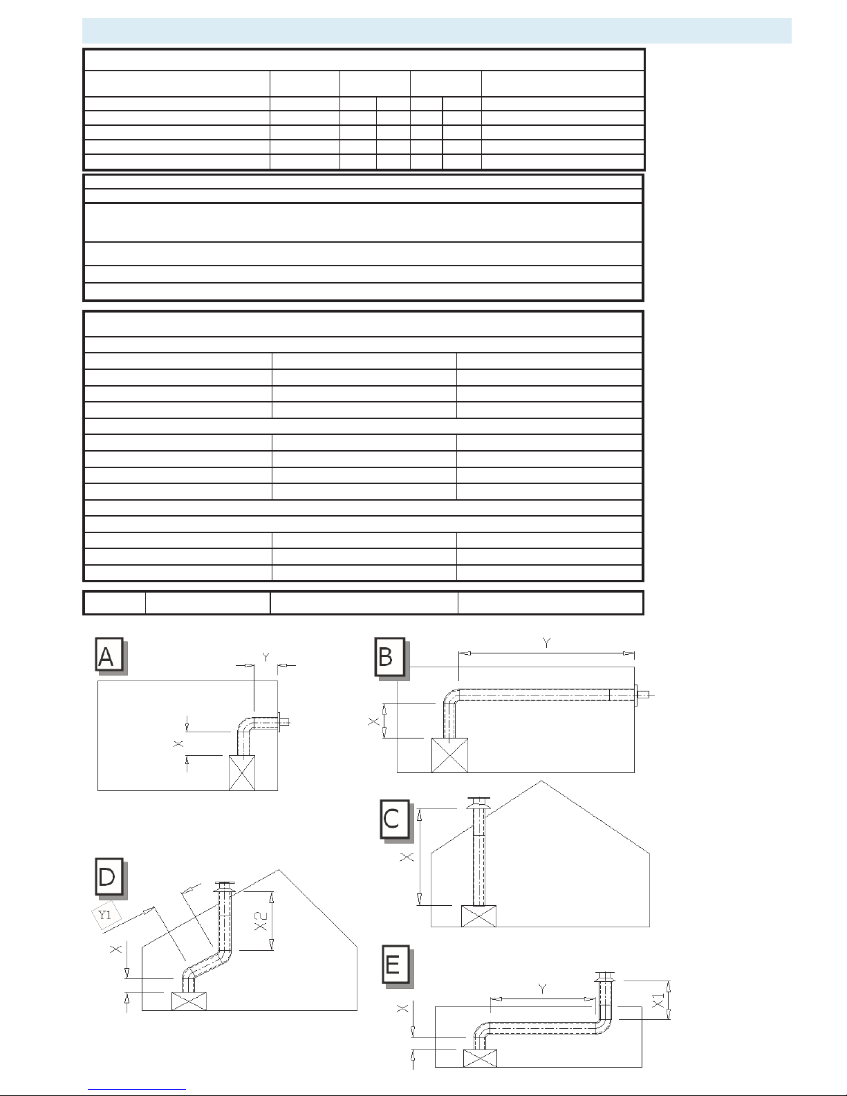
7. CONCENTRIC CHIMNEY LAY OUT
45° elbow: calculation length 1 meter
90° elbow: calculation length 2 meter
Reduction from the diameter of the two 130-200 100-150 can be performed, see C, D and E Examples below. These are
the basic recommended lengths & lay outs. When deviated lay out or lengths are occurring please ask your supplier for
more detailed advice
* recommended length excluding roof or wall terminals. Always starting length of 1 meter!
** Vertical: horizontal ratio X + X1 + X2 : Y ≥ 2 : 1
*** Vertical: horizontal ratio X + X1 : Y ≥ 2 : 1
Restriction conditions all gas types
vertical lay out
restriction Baffle plate
0-3 meter no yes
3-7 meter 30 mm yes
7-12 meter 50 mm yes
Vertical path with bends
45° : X total - Y = 3-6 meter 30 mm
yes
45° : X total - Y = 6-12 meter 50 mm
yes
90° : X total - Y = 4-6 meter 30 mm
yes
90° : X total - Y = 6-12 meter 50 mm
yes
Horizontal lay out
maximum 3 meter + wall outlet
restriction Baffle plate
1m 90° wall outlet no no
1-4m 90° 5.5m wall outlet no no
Table of concentric chimney lay out
Lay out
Illustration
X total in
meter
Y total in
meter
Restriction
min* max* min* max* Stanford/Harmony 25-35
Indirect exterior wall outlet A-B 1 5 0 3 none
Roof termination without elbows
C 2 12 from 3 meter
Roof termination with 45º elbows** D 3 12 0 4 from X totaal - Y > 3 meter
Roof termination with 90º elbows*** E 1 12 0 2 from X + X1- Y > 4 meter
SH35 LPG
1m 90° wall outlet
45 mm no
Page 13

Pag.13
The concentric flue system is composed of an inner- and an outer tube.
These tubes are concentrically arranged; through the inner tube, the combustion gases are evacuated and the fresh
combustion air is supplied between the inner and outer tube.
9.1 Components of the concentric flue system.
Different connections are possible using the concentric flue system. These are:
Through the roof face and through the exterior wall.
There are various options for mounting the lay outs for this system,
however, there are a few important requirements/conditions:
* The maximum recommended vertical flue length is 12 metres (the sum of the flue length and the
calculation lengths for the bends).
* 90° bends have a 2-metre horizontal calculation length.
* 45° bends have a 1-metre horizontal calculation length.
* The outlet can be installed at any point on the roof face or exterior wall (supply and discharge in
an identical pressure area), but must meet applicable regulations.
* Ducts may not be insulated.
8.2 Construction of concentric flue system
Indirect wall connection.
* The outlet may be installed in the wall, taking any hindrance to the surrounding area into consideration,
according to national, regional, local standards and regulations.
Ensure wind pressure on the flue terminal is not too extreme, such as a balcony, flat roof,
corners and in small alleys etc., as this may negatively influence the unit efficiency.
* Provide a recess in the exterior wall of around 155 mm for concentric 100-150, and 205 mm for
concentric 130-200. (in a flammable wall ensure there is 50 mm of extra space around the outer
pipe and use fireproof casing) and fix the exterior wall duct with the wall plate to the outer side of
the wall. The wall plate of the exterior wall duct must be sealed sufficiently against the wall on
the outside, to avoid moisture and/or flue gas leaks into the living space.
* The flue should be cased if necessary. Sufficient fireproof measures must also be taken when
the flue is being mounted along flammable materials.
* Determine the position of the unit and outlet and begin construction of the flue with the connection
on the unit, paying attention to the direction of installation and connecting the elements by means
of locking bands.
* An adjustable length can be used between the bends or when connecting to the unit.
If necessary, use wall brackets to support the flue.
Rooftermination.
* The flue terminal can be located at any random place on the roof face (supply and exhaust in
identical pressure areas) and must meet the applicable rules and regulations.
* A roof flashing for a flat roof or a lead flashing for sloping tiled roofs can be used for a
watertight connection. Use various elbows for making the proper connection, if required.
The recess in the roof decking should be 5 cm larger all around, to ensure sufficient fire resistance.
* One needs to take into account the regulation regarding fire resistance between rooms
(See national, regional, local standards and regulations). A casing made of fireproof material
(e.g. 12 mm Promatect fire resistant plate) must be used at 25mm from the outside duct.
* Determine the position of the unit and outlet and begin construction of the flue with the connection
on the unit (always 1 metre vertical first), paying attention to the direction of installation!
The flue must be installed dripless. Connect the elements by using locking bands.
Ensure the gas tightness of all connections is correct.
* An adjustable length can be used between the elbows or when making the connection to the unit and/or the
roof terminal. Use 2 wall brackets to support the flue on each floor.
8. CONCENTRIC FLUE SYSTEM
NOTICE
Ensure the restriction plate in the fire is mounted in the correct manner, as indicated in these instructions.
The correct restriction plate will provide the unit with the most optimal efficiency, flame image and combustion.
Mounting an incorrectly placed restriction plate may cause malfunction of the unit.
Page 14

Pag.14
8.3 Installation instructions regarding existing flues.
Instructions
The flue gas exhaust system falls within category C91 and must be built in accordance with national rules
and regulations and the instructions of the manufacturer, as specified in the documentation and installation
instructions. This means, among other things, that the existing chimney must not be smaller than 150 mm
round / square, but no larger than 200 mm, and not ventilated by grilles etc. In the case of larger chimney
size, a flexible hose of around 150 mm may possibly be used in combination with a flexible hose of around
100 mm, as described below. For other situations, you should consult your supplier / manufacturer.
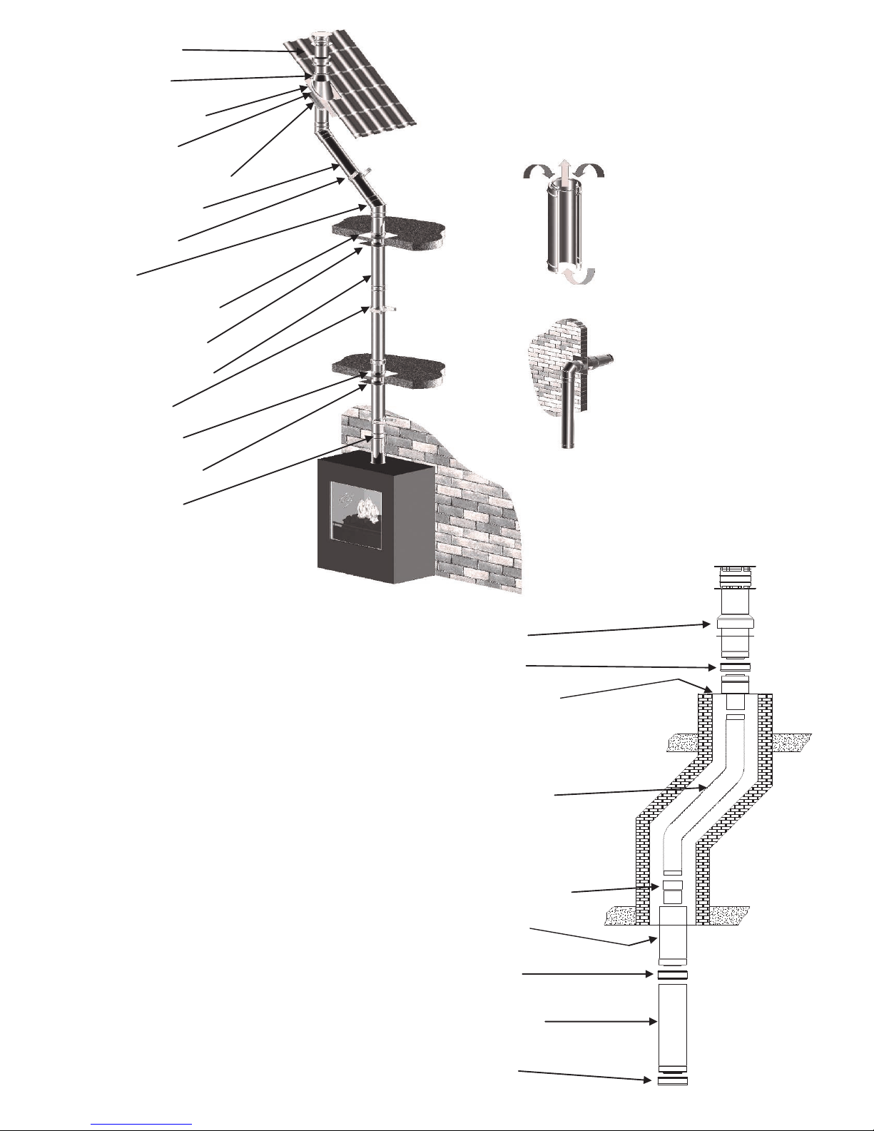
8.4 Components
Check all parts for damage before commencing the installation. You will require the following parts for
converting a brickwork duct to a balanced flue concentric duct :
1. Locking bands 7. Renovation kit mounting plate
2. CC chimney elements 8. Locking band
3. Renovation kit outer adjustable pipe dia 150mm 9. Roof terminal
4. Renovation kit inner ceiling plate
5. Renovation kit adjustable pipe dia 100mm
6. Flexible liner AISI 316 dia 100 /107mm
Note: The renovation kit consists of parts 4, 5 and 7.
8.5 Installation
* Guide the flexible hose (6) through the existing duct.
* Attach the adjustable pipe (5) to the bottom of the flexible hose and secure this in place using 2 parkers.
* Level the bottom side of the adjustable pipe (5) with the ceiling of existing chimney.
* Shorten the flexible hose to approximately 100 mm above the existing chimney top.
* Attach the mounting plate / connecting piece (7) to the flexible hose on the roof.
Clamp it with a hose band and secure it in place using a parker.
* Attach the mounting plate / connecting piece (7) to the chimney top, using silicone sealant to make it
watertight secure with stainless steel screws.
* Install the roof terminal (9) and secure it in place using the supplied locking band (8).
* The adjustable pipe (5) will stick about 100mm below ceiling/existing chimney. Mount the inner ceiling
plate (4) gastight to the ceiling/existing chimney with silicone kit and fixing screws.
* Position the unit in accordance with the instructions of the unit manufacturer.
* Always install a minimum of 1 metre of concentric duct type THC CC100-150 (2), or 130-200 mm with
reduction to 100-150 mm.
8.6 Cleaning and maintenance.
This appliance should be inspected and serviced once a year by a qualified, competent and registered person.
The inspection and maintenance must at least ensure that the appliance is working correctly and safely.
It is advisable to clean the appliance of any dust and debris before regularly during the heating season and
especially if the appliance has not been used for some time. This can be done with a soft brush and a vacuum
cleaner or a damp cloth and if required a non-abrasive cleaning agent. Do not use corrosive or abrasive
substances to clean the appliance.
Page 15
Pag.15
Roof terminal
Storm collar
Lead roof flashing
Roof support
Fire stop plate pitched
Adjustable length
Wall bracket
Elbow
Floor/ceiling support
Fire stop plate flat
Concentric element
Wall bracket
Floor support
Fire stop plate flat
Locking band
9. Roof terminal
8. Locking band
7. Chimney connection
set (Renovation kit)
6. Flexible hose 316L
5. Slider (Renovation kit)
4. Connection set
(Renovation kit)
3. Locking band
2. Adjustable length
1. Locking band
Page 16
Pag.16
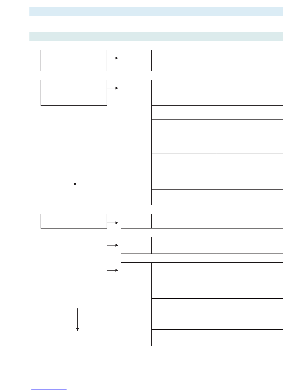
No ACTION Possible problem/cause Solution
1.
Option: wall switch START:
press ON button > wall switch
works.
NO
Bent pin on switch, or cable
not operating properly.
Straighten pin, replace wall
switch or cable.
1.
Manual transmitter START:
press both buttons to start
ignition sequence.
Beep will occur each second
NO
Manual transmitter battery
low.
Replace battery, 2x AAA 1.5V
quality alkaline!
Receiver batteries low. Replace batteries, 2x AA 1.5V
quality alkaline!
Optional mains adapter not
operating properly.
Check mains adapter.
Check coding of transmitter
and receiver.
Learn in new code, see
instructions and label on
receiver.
OK
Transmitter/receiver range
limited.
1. Move antenna cable,
see instructions.
2. Replace receiver.
Optional wall switch / cabling
not operating properly.
Replace wall switch / cabling.
Receiver fuse blown (in older
versions only).
Replace receiver.
2.
Magnet unit in gas valve is
energised (audible click)
NO
No beep Impulse magnet not
operating properly.
Replace gas valve.
NO
3 short
beeps
Receiver batteries low. Replace batteries, 4x 1.5V AA
quality alkaline!
NO
1 long beep ON/OFF switch on gas valve
in OFF position
Set switch to ON.
8-wire cable between receiver
and gas valve defective /
poor contact.
Check cable, especially in case
of plug connection.
OK
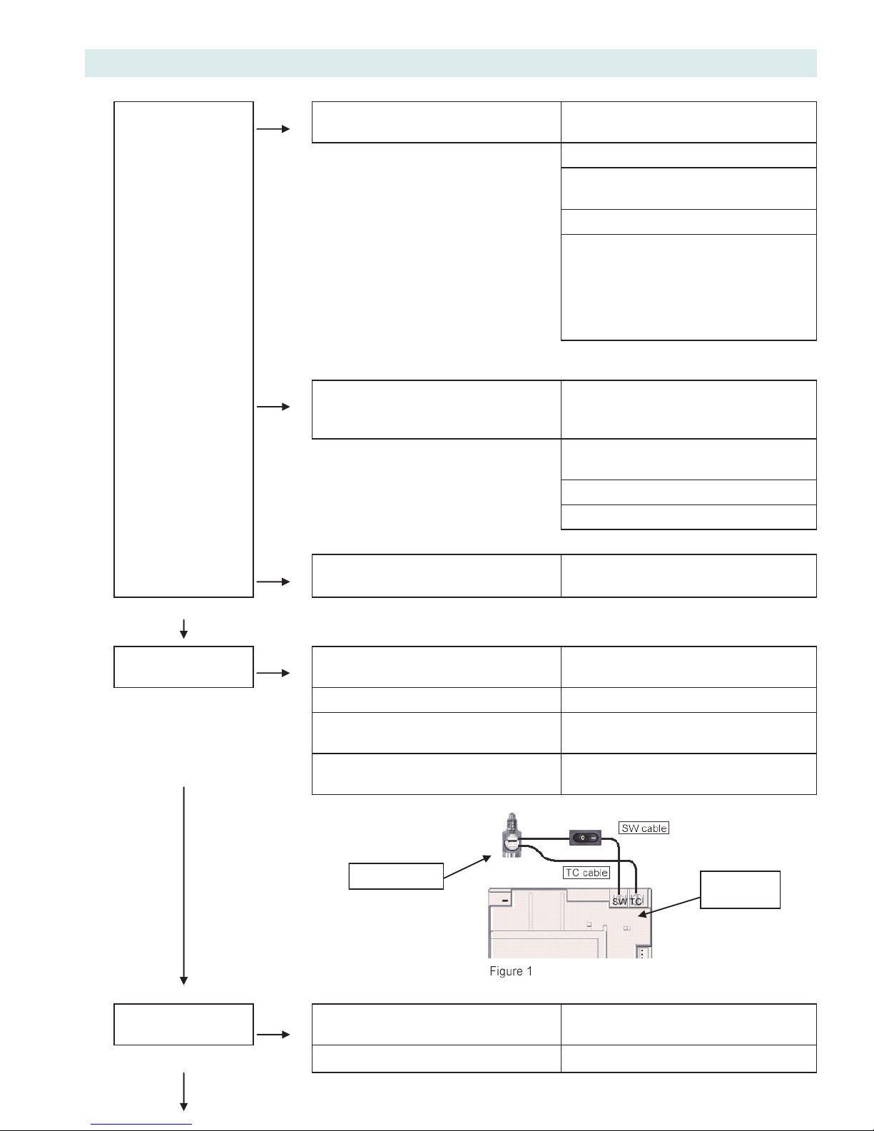
Switch cable disconnected. Check switch cable, see fig. 1
on page 18
Motor not operating properly. Replace gas valve.
Micro switch on gas valve not
operating properly.
Replace gas valve.
9. TROUBLESHOOTING LIST MERTIK GV60
Page 17
Pag.17
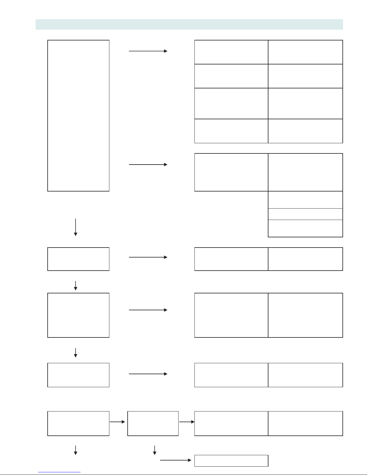
No ACTION Possible problem/cause Solution
3.
NO
Ignition components not operating
properly.
Check connection between cable & IGN
electrode.
Check IGN electrode spark gap.
Check IGN electrode for discharge to
ground (break in ceramic).
Check IGN cable for damage
Continuous spark
Increase distance between IGN cable and
all metal parts. Check that spark does
not discharge to ground at location of
spark plug connection. Shorten cable if
possible. If applicable, provide extra
insulation with silicon hose etc.
Spark will occur each
second.
NO
IGN sequence stops, no pilot flame.
No reaction to transmitter command
(receiver does not react).
Press RESET button, see instructions.
Add ground wire between pilot burner
and gas valve.
Do not coil the IGN cable.
Shorten IGN cable if possible.
NO
IGN sequence stops, no pilot flame.
Transmitter command is possible.
IGN sequence stops, no pilot flame.
Transmitter command is possible.
OK
4.
Pilot lit.
NO
TC and SW cable reversed. Check connection of cable to receiver
and interrupter, see fig. 1.
Impulse magnet not operating properly. Replace gas valve.
Short between interrupter and SW
cable.
Check connection to interrupter.
OK
No gas magnet unit drops after 30
second audible count).
Check gas supply to gas valve.
5.
Sparking stops after
pilot is lit
NO
Short between interrupter and TC cable. Check connection to interrupter,
see fig. 1
OK
Electronic measuring amplifier defective. Replace receiver.
Interrupter
Receiver
Page 18
Pag.18
No ACTION Possible problem/cause Solution
6.
NO
Resistance in thermo
current circuit too high.
Check cables and
connections in thermo
current circuit.
Magnet unit drops
(audible click)
Not enough heat on
thermocouple.
Check position of pilot to
thermocouple and intensity
of pilot flame.
Motor turns to main
gas and pilot stays lit.
Low voltage from
thermocouple.
Check connections and, if
necessary, replace
thermocouple. Do not over
tighten the connections!
Short because
thermocouple end is
damaged.
Replace thermocouple, do
not overtighten the
connections!
NO
IGN sequence stops. No
reaction to transmitter
command (receiver does
not react).
Press RESET button, see
instructions.
Add ground wire between
pilot burner and gas valve.
OK
Do not coil the IGN cable.
Shorten IGN cable if
possible.
7.
Main burner is lit.
NO
Gas valve manual knob in
“MAN” position.
Turn knob to “ON” position.
OK
8.
Main burner stays lit.
NO
Too much / too little air
flow / draft at pilot, blows
out or is smothered.
Check whether restriction
plate has been correctly
applied in unit, see
instructions. Poor flue
location, check correctness
of layout and connections.
OK
9.
Magnet unit drops
while motor turns.
3 beeps
NO
Receiver batteries low. Replace batteries, 1.5V AA
quality alkaline!
System can be
switched OFF via
remote control.
NO
System can be
switched OFF via
ON/OFF switch.
NO
Short between TC and SW
cable.
Check connection to
interrupter block.
YES
YES
OK OK
Replace gas valve.
Page 19
Pag.19
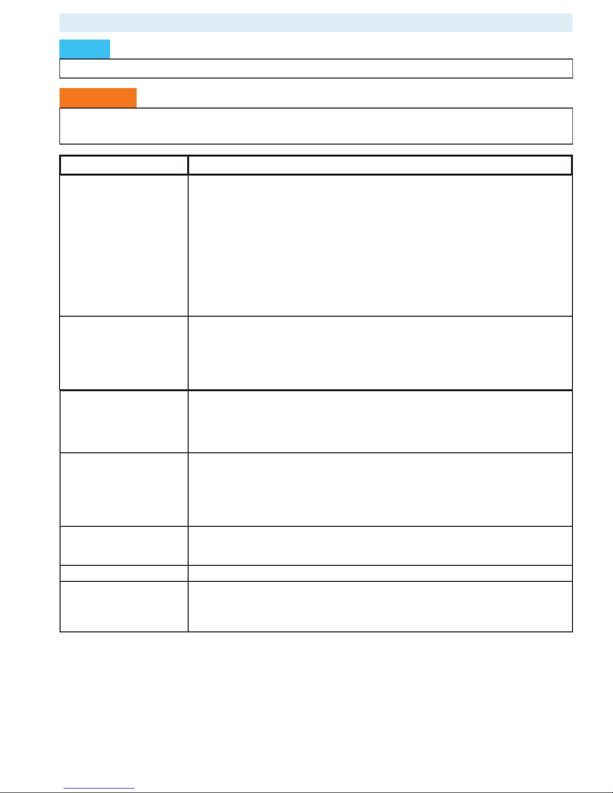
SYMPTOM ACTION TO BE TAKEN
The pilot flame will not light
after repeated ignition.
1. There is air in the pipes if you switch the unit on for the first time or after a service. It
will take a little while until all the air has flowed out of the pipes and gas flows through
that can be ignited. Take it away and try to switch the pilot flame on several times in
order to allow the air to escape.
2. See whether the gas pipe to the unit is open and if there is sufficient gas pressure to
the unit.
3. Check whether there are sparks between the spark electrode and the pilot. If there are
no sparks:
a) Check whether the connection between the electrode and the ignition is broken or
faulty.
b) Check whether the spark short circuits at another point or jumps.
c) Check whether the electrode is broken.
The pilot flame will not
remain alight after ignition.
1. Check whether the pilot flame is large enough to burn around the thermocouple.
If the flame is too small, you need to check the gas feed pressure. If the size of the
pilot flame cannot be adjusted, there may be an obstruction in the pilot.
2. Check whether the thermocouple interrupter is connected to the gas valve properly.
3. Check that the gas valve is not faulty.
4. Check whether the restriction plate has been placed according to instructions
The main burner goes out
when the unit is warm.
1. This can be a normal effect of the thermostat.
Check whether the pilot flame is able to heat the thermocouple adequately. If the pilot
flame is too small then the gas pipe or the pilot flame adjustment need to be checked.
2. Check whether the restriction plate has been placed according to instructions (see page
25).
Soot deposits on the glass. 1. Check whether the lava split is lying on the burner in the correct manner.
2. Check if the pilot burner is free from burner filling.
3. Check whether there is any blockage in the burner openings.
4. Check if the flue tube is functioning correctly and if the flue tube is not hindered or
blocked.
5. Check the pipe pressure.
Sharp blue flames that are
released by the burner or a
pilot that burns too wildly.
1. Check whether the restriction plate has been used.
Weak (stifling) pilot flame. 1. Check the pilot burner pressure or duct pathway.
Main burner will not burn
after the pilot burner is
functioning.
1. Check if the motor button turns and whether the batteries are empty.
2. Possible defect in the gas block.
3. Check whether the pilot flame ignites the burner well.
4. Check that the burner opening is not blocked.
10. PROBLEMS AND POSSIBLE SOLUTIONS
WARNING
Solving problems with your unit, whether gas related or electrical, must always be performed by
a qualified technician.
NOTICE
Please first check if all guidelines were followed before attempting to solve any problems with the unit.
Page 20
Pag.20
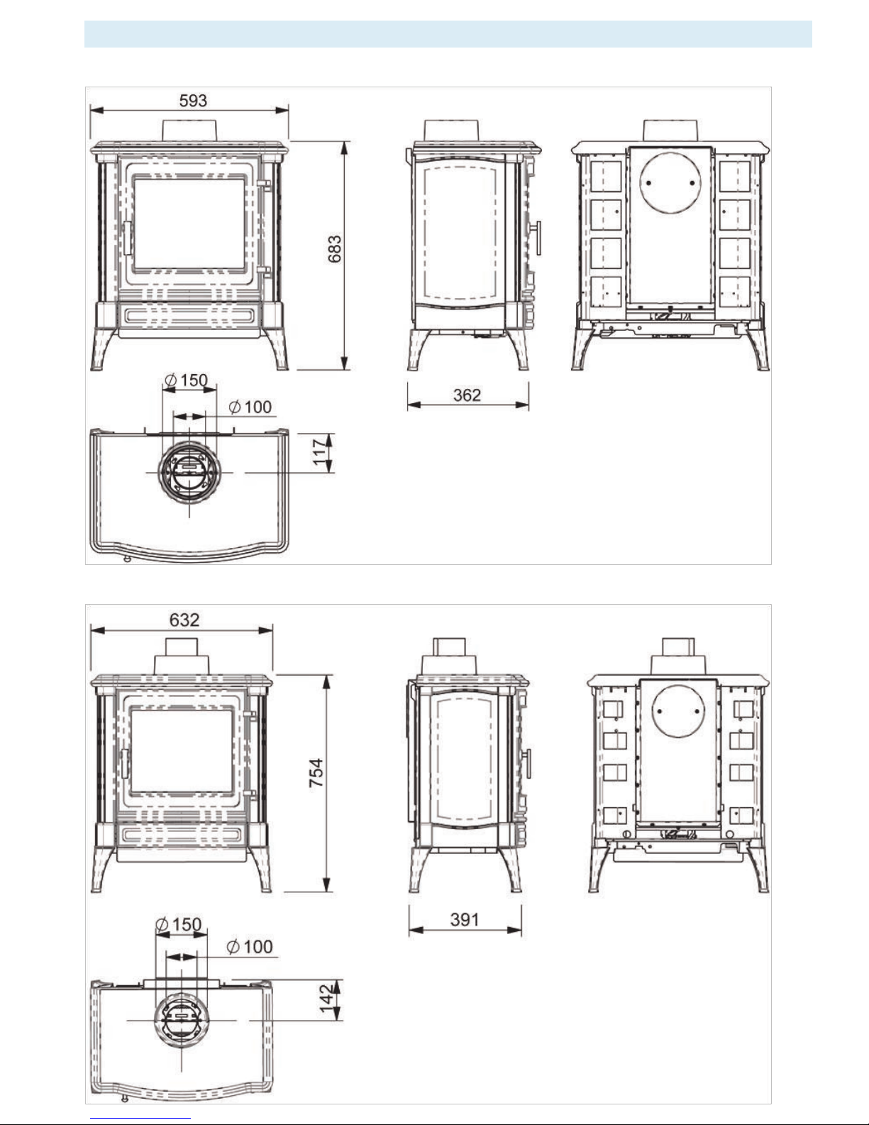
APPENDIX 1 DIMENSIONAL DRAWINGS
Stanford / Harmony 25 TOP CONNECTION
Stanford / Harmony 35 TOP CONNECTION
Page 21
Pag.21
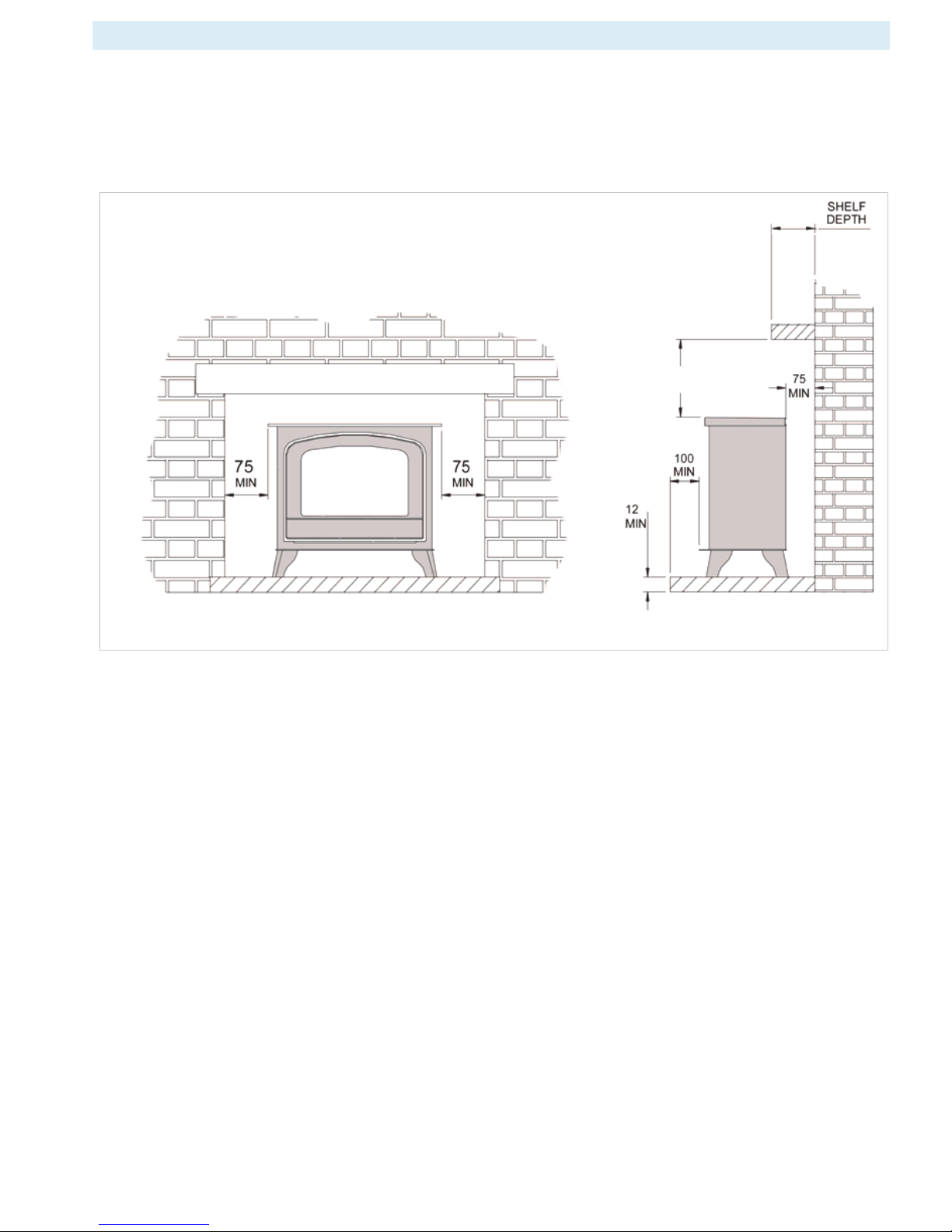
APPENDIX 2 INSTALLATION EXAMPLES
The stove must be located at least 280mm from any combustible materials.
A combustible shelf may be fitted over the appliance, if in the case of a 150mm or less deep shelf, there
is at least 280mm clearance above the top of the stove. The shelf depth may increase at the same rate as
the increase in clearance; i.e. a shelf depth of 200mm would require a clearance of 330mm.
280 MIN
150
Page 22
Pag.22
APPENDIX 3 FITTING LOG SET
Stanford / Harmony 25 (NG-LPG)
Page 23
Pag.23
Stanford / Harmony 35 (NG)
Page 24
Pag.24
Industrias Hergóm,
S.A. Soto de la Marina.
Cantabria. España
Stanford / Harmony 35 (LPG)
Place behind the horizontal log embers to break the high-pointed flame
Place embers under the open space
Horizontal log
 Loading...