

Page 1

Drivers for Windows
Detonator XP
User’s Guide
Driver Version 21.83
NVIDIA Corporation
October 11, 2001
Page 2

Published by
NVIDIA Corporation
2701 San Tomas Expressway
Santa Clara, CA 95050
Copyright © 2001 NVIDIA Corporation. All rights reserved.
This software may not, in whole or in part, be copied through any means, mechanical, electromechanical,
or otherwise, without the express permission of NVIDIA Corporation.
Information furnished is believed to be accurate and reliable. However, NVIDIA assumes no
responsibility for the consequences of use of such information nor for any infringement of patents or other
rights of third parties, which may result from its use. No License is granted by implication or otherwise
under any patent or patent rights of NVIDIA Corporation.
Specifications mentioned in the software are subject to change without notice.
NVIDIA Corporation products are not authorized for use as critical components in life suppor t devices or
systems without express written approval of NVIDIA Corporation.
NVIDIA, the NVIDIA logo, GeForce, GeForce2, GeForce2 Pro, GeForce2 Ultra, GeForce2 Go,
GeForce2 MX, GeForce2 GTS, GeForce 256, GeForce3, Quadro2, NVIDIA Quadro2, Quadro2 Pro,
Quadro2 MXR, Quadro, NVIDIA Quadro, Vanta, NVIDIA Vanta, TNT2, NVIDIA TNT2, TNT, NVIDIA
TNT, RIVA, NVIDIA RIVA, NVIDIA RIVA 128ZX, NVIDIA RIVA 128, XPress Link, nfiniteFX,
Detonator, and TwinView are trademarks or registered trademarks of NVIDIA Corporation in the United
States and/or other countries.
3D Studio Max is a registered trademark of Discreet.
Adobe, Photoshop, Premiere are registered trademarks of Adobe Systems Incorporated.
CDRS is a trademark and Pro/ENGINEER is a registered trademark of Parametric Technology
Corporation.
Intel and Pentium are registered trademarks of Intel.
Microsoft, Wi ndows, W indo ws NT, Windows XP, D irect3D, DirectDraw, DirectX, PowerPoint , and Xbox
are trademarks or registered trademarks of Microsoft Corporation.
OpenGL is a registered trademark of Silicon Graphics Inc.
SPECglperf and SPECviewperf are trademarks of the Standard Performance Evaluation Corporation.
Other company and product names may be trademarks or registered trademarks of the respective owners
with which they are associated.
Page 3

Detonator XP User’s Guide
Table of Contents
1. About the
Detonator XP Unified Driver
Overview of Features & Benefits. . . . . . . . . . 1
OpenGL 1.3 ICD with NVIDIA Extensions. . . 2
OpenGL Performance Optimizations. . . . . . 3
Optimized DirectX Pipeline with NVIDIA Pixel/
Vertex Shaders . . . . . . . . . . . . . . . . . 4
Detonator XPress Link. . . . . . . . . . . . . . 4
System Requirements. . . . . . . . . . . . . . . . 5
Operating Systems. . . . . . . . . . . . . . . . 5
NVIDIA Products (GPUs) . . . . . . . . . . . . 5
Notes & Conventions . . . . . . . . . . . . . . . . 6
NVIDIA Single-Display vs. Dual-Display
cards . . . . . . . . . . . . . . . . . . . . . . 6
NVIDIA Control Panels: Windows XP/2000/
NT 4.0 . . . . . . . . . . . . . . . . . . . . . 6
NVIDIA Co ntrol Panel Examples (GeForce2
MX & GeForce3) . . . . . . . . . . . . . . . 6
2. NVIDIA Driver Feature History
Summary of Recent Driver Enhancements . . . . 7
Summary of Earlier Driver Enhancements . . . . 8
TwinView . . . . . . . . . . . . . . . . . . . . . 8
Virtual Desktop . . . . . . . . . . . . . . . . 8
Video Mirror . . . . . . . . . . . . . . . . . . 8
Desktop Manager. . . . . . . . . . . . . . . 9
Digital Vibrance . . . . . . . . . . . . . . . . . . 9
OpenGL . . . . . . . . . . . . . . . . . . . . . . 9
OpenGL 1.2 Core Enhancements . . . . . 9
OpenGL Extensions . . . . . . . . . . . . . 1 0
OpenGL Performance Enhancements . . . 10
Direct3D . . . . . . . . . . . . . . . . . . . . . . 11
Cursor Trails Support . . . . . . . . . . . . . . 11
Control Panels . . . . . . . . . . . . . . . . . . 11
3. The GeForce3 Family of GPUs
Features and Benefits . . . . . . . . . . . . . . . .13
Accessing the GeForce3 Control Panel . . . . . .14
4. TwinView Applications
TwinView Display Device Options . . . . . . . . .17
TwinView Modes for Using Your Display Setup .18
TwinView Applications. . . . . . . . . . . . . . . . 19
5. TwinView Basics: Windows 9x
Accessing the T w in V ie w Panel . . . . . . . . . . 21
Accessing the Configuratio n Opt ion s. . . . . . . 25
Standard Mode . . . . . . . . . . . . . . . . . . . 25
Switching Display Device: Standard Mode. . 27
Primary Display . . . . . . . . . . . . . . . 27
Select Output Device . . . . . . . . . . . . 27
Clone Mode . . . . . . . . . . . . . . . . . . . . . 31
Switching Secondary Displays: Clone Mode. 33
Switching Secondary to Primary Display: Clone
Mode . . . . . . . . . . . . . . . . . . . . . . 35
Change Resolution: Clo ne Mo de (Virtual
Desktop) . . . . . . . . . . . . . . . . . . . . 37
Extended Desktop: Windows 98/Me . . . . . . . 39
Configuring Extended Desktop . . . . . . . . 42
Other Configuration Options. . . . . . . . . . . . 44
6. TwinView Basics:
Windows XP/2000/NT 4.0
Notes Before You Begin . . . . . . . . . . . . . . 45
Accessing the T w in V ie w Panel: Win dows XP . . 46
TwinView Enabled by Default (Windows XP
SingleView). . . . . . . . . . . . . . . . . . . 46
Windows XP DualView . . . . . . . . . . . . . 46
SingleView Mode . . . . . . . . . . . . . . 49
DualView Mode . . . . . . . . . . . . . . . 49
Enabling DualView . . . . . . . . . . . . . . . 49
Configuring DualView Settings. . . . . . . . . 51
NVIDIA Panels With DualView Enabled . . . 52
Accessing the T w in V iew Panel: Windows NT 4.0/
2000 . . . . . . . . . . . . . . . . . . . . . . . . 53
Accessing the Configuratio n Opt ion s. . . . . . . 55
Standard Mode . . . . . . . . . . . . . . . . . . . 56
Switching Display Device: Standard Mode. . 57
Clone Mode . . . . . . . . . . . . . . . . . . . . . 59
Switching Secondary Displays: Clone Mode. 63
Switching Secondary to Primary Display: Clone
Mode . . . . . . . . . . . . . . . . . . . . . . 66
Change Resolution: Clo ne Mo de (Virtual
Desktop) . . . . . . . . . . . . . . . . . . . . 68
Horizontal & Vertical Span Modes . . . . . . . . 69
Switching Display Device: Span Modes . . . 70
Other Configuration Options. . . . . . . . . . . . 77
7. Device Selection & Configuration
Accessing the Device Selection Control Panel . 79
NVIDIA Corporation
i
Page 4

Drivers for Windows Table of Contents
Switching Displays. . . . . . . . . . . . . . . . . . 83
Device Adjustments: Analog Monitor . . . . . . .85
Screen Adjustment. . . . . . . . . . . . . . . . 8 5
Display Timing . . . . . . . . . . . . . . . . . .86
Device Adjustments: Digital Flat Panel . . . . . .87
Flat Panel D isplay . . . . . . . . . . . . . . . . 87
Monitor Settings (Refresh Frequency):
Secondary Display . . . . . . . . . . . . . . . 89
TV Settings . . . . . . . . . . . . . . . . . . . . . .91
Accessing the TV Option in No n-TwinView Mode
91
Change Format: Regional Settings. . . . . . . 91
Video Outp ut Format. . . . . . . . . . . . . . .91
Device Adjustments: TV Output . . . . . . . .93
8. Video Mirror
Accessing Video Mirror . . . . . . . . . . . . . . .95
Overlay Controls . . . . . . . . . . . . . . . . .96
Overlay Settings . . . . . . . . . . . . . . . 97
Video Mirror Controls . . . . . . . . . . . . . . 99
TwinView Clone Mode . . . . . . . . . . . . 99
Windows 9x Extended Desktop Mode . . 100
Video Mirror Settings . . . . . . . . . . . . . . . 101
9. Desktop Manager
Notes Before You Begin. . . . . . . . . . . . . . 105
Features Overview. . . . . . . . . . . . . . . . . 106
Windows 2000/NT 4.0 vs. Windows 9x . . . 106
Enabling Desktop Manager. . . . . . . . . . . . 107
Tips on Using Desktop Manager . . . . . . . 109
Application Management . . . . . . . . . . . . . 109
Adding an Application to Desktop Manager. 109
Hot Keys . . . . . . . . . . . . . . . . . . . . . . 114
Task Switcher . . . . . . . . . . . . . . . . . . 11 6
Global Settings. . . . . . . . . . . . . . . . . . . 11 7
Pop-up Settings . . . . . . . . . . . . . . . . . . 120
Zoom Settings . . . . . . . . . . . . . . . . . . . 121
Using Zoom . . . . . . . . . . . . . . . . . . . 123
Custom OpenGL Application Settings. . .135
Direct3D Settings . . . . . . . . . . . . . . . . . .135
Descript ion of Direct3D Settings. . . . . . . .135
Description of More Direct3D Settings . . . .137
3D Antialiasing Settings . . . . . . . . . . . . . .138
Description of 3D Antialiasing Settings . . . .139
Additional Quincunx Antialiasing Setting:
GeForce3 only . . . . . . . . . . . . . . . . .139
Overlay Controls Panel. . . . . . . . . . . . . . .140
Description of Overlay Settings . . . . . . . .143
A. NVIDIA Dual-Card Configuration
Setting Up the Dual NVIDIA Cards . . . . . . . .145
Enabling the First Card: GeForce3 . . . . . . . .146
Enabling the Second Card: GeForce2 MX. . . .150
Accessing Dual Cards & Configurations With
QuickTweak . . . . . . . . . . . . . . . . . . . . 1 54
10. Additional Features and
Enhancements
Desktop Utilities . . . . . . . . . . . . . . . . . . 125
Enabling the NVIDIA QuickTweak Icon . . . 126
Color Correction Panel . . . . . . . . . . . . . . 128
Color Correction Settings . . . . . . . . . . . 129
OpenGL Settings. . . . . . . . . . . . . . . . . . 130
Description of OpenGL Settings . . . . . . . 132
Performance and Compatibility Options . 132
Custom OpenGL Settings . . . . . . . . . 135
ii
NVIDIA Corporation
Page 5

Detonator XP User’s Guide
List of Tables
Table 1.1 Operating System Requirements. . . . . . . . . . . . . . . . . . . . . . . . . . . . . . . . . . . . 5
Table 1.2 Supported NVIDIA GPUs . . . . . . . . . . . . . . . . . . . . . . . . . . . . . . . . . . . . . . . . 5
Table 2.1 OpenGL Extensions Modified. . . . . . . . . . . . . . . . . . . . . . . . . . . . . . . . . . . . . 10
Table 8.1 Video Mirror Settings . . . . . . . . . . . . . . . . . . . . . . . . . . . . . . . . . . . . . . . . .101
NVIDIA Corporation
iii
Page 6

Detonator XP User’s Guide
List of Figures
Figure 3.1 GeForce3 Control Panel . . . . . . . . . . . . . . . . . . . . . . . . . . . . . . . . . . . . . . . . . 15
Figure 3.2 3D Antialiasing Control Panel . . . . . . . . . . . . . . . . . . . . . . . . . . . . . . . . . . . . . 16
Figure 5.1 Display Properties Settings: Windows 98. . . . . . . . . . . . . . . . . . . . . . . . . . . . . . . . 23
Figure 5.2 Disabling Extended Desktop: Windows 98 . . . . . . . . . . . . . . . . . . . . . . . . . . . . . . . 23
Figure 5.3 GeForce2 MX/MX 400 Properties Panels: Wi nd ows 98 . . . . . . . . . . . . . . . . . . . . . . . . 24
Figure 5.4 GeForce2 MX Control Pane l: Windows 98 . . . . . . . . . . . . . . . . . . . . . . . . . . . . . . . 24
Figure 5.5 TwinView Std (dual-display) with Context Menu: Windows 98 . . . . . . . . . . . . . . . . . . . . 26
Figure 5.6 TwinView Std. Mode (single-display) Context Menu: Windows 98 . . . . . . . . . . . . . . . . . . 26
Figure 5.7 TwinView Device Selection (Analog Monitor): Windows 98. . . . . . . . . . . . . . . . . . . . . . 27
Figure 5.8 TwinView Device Selection (Digital Flat Panel): Windows 98 . . . . . . . . . . . . . . . . . . . . . 28
Figure 5.9 TwinView Device Selection (TV): Windows 98 . . . . . . . . . . . . . . . . . . . . . . . . . . . . 28
Figure 5.10 Switching Output Device Message: Windows 98 . . . . . . . . . . . . . . . . . . . . . . . . . . . 29
Figure 5.11 Switching Output Device Message: Windows 98 . . . . . . . . . . . . . . . . . . . . . . . . . . . 29
Figure 5.12 DFP Option Enabled on Digital Flat Panel Display: Windows 98. . . . . . . . . . . . . . . . . . . 29
Figure 5.13 TV Option Enabled on T V Display: Windows 98 . . . . . . . . . . . . . . . . . . . . . . . . . . . 30
Figure 5.14 TwinView Std. Mode (Display 1 = DFP): Windows 98 . . . . . . . . . . . . . . . . . . . . . . . . 30
Figure 5.15 TwinView Std. Mode (Display 1 = TV): Windows 98. . . . . . . . . . . . . . . . . . . . . . . . . 31
Figure 5.16 TwinView Clone Mode Menu (Display 1 = CRT): Windows 98 . . . . . . . . . . . . . . . . . . . 32
Figure 5.17 TwinView Clone Mode Men u (Display 2 = DFP): Windows 98 . . . . . . . . . . . . . . . . . . . 33
Figure 5.18 TwinView Clone Device Selection TV Option: Windows 98 . . . . . . . . . . . . . . . . . . . . . 34
Figure 5.19 TwinView Clone Device Selection Panel on TV: Windows 98 . . . . . . . . . . . . . . . . . . . . 34
Figure 5.20 TwinView Clone Mode (Dis play 2 = TV): Windows 98. . . . . . . . . . . . . . . . . . . . . . . . 35
Figure 5.21 TwinView Clone Mode (Display 1 = DFP): Windows 98 . . . . . . . . . . . . . . . . . . . . . . . 36
Figure 5.22 TwinView Clone Mode (Dis play 1 = TV): Windows 98. . . . . . . . . . . . . . . . . . . . . . . . 36
Figure 5.23 TwinView Clone Mode (Dis play 2 = CRT): Windows 98 . . . . . . . . . . . . . . . . . . . . . . . 37
Figure 5.24 TwinView Clone Mode Device Configuration: Windows 98 . . . . . . . . . . . . . . . . . . . . . 38
Figure 5.25 Display Settings: Win dow s 98 . . . . . . . . . . . . . . . . . . . . . . . . . . . . . . . . . . . . . 40
Figure 5.26 Enabling Extended Desktop (1): Windows 98 . . . . . . . . . . . . . . . . . . . . . . . . . . . . . 40
Figure 5.27 Enabling Extended Desktop (2): Windows 98 . . . . . . . . . . . . . . . . . . . . . . . . . . . . . 41
Figure 5.28 TwinView Tab Disabled: Windows 98 . . . . . . . . . . . . . . . . . . . . . . . . . . . . . . . . . 41
Figure 5.29 Display Settings (Horizontal): Windows 98 . . . . . . . . . . . . . . . . . . . . . . . . . . . . . . 42
Figure 5.30 Display Settings (Vertical): Windows 98 . . . . . . . . . . . . . . . . . . . . . . . . . . . . . . . 43
Figure 5.31 Display Settings (Diagonal): Windows 98. . . . . . . . . . . . . . . . . . . . . . . . . . . . . . . 43
Figure 6.1 Display Properties Settings: Windows XP . . . . . . . . . . . . . . . . . . . . . . . . . . . . . . . 47
Figure 6.2 Advanced Options: W indows XP . . . . . . . . . . . . . . . . . . . . . . . . . . . . . . . . . . . . 47
Figure 6.3 GeForce2 MX Control Panel: Window s XP . . . . . . . . . . . . . . . . . . . . . . . . . . . . . . 48
NVIDIA Corporation
iv
Page 7

Drivers for Windows List of Figures
Figure 6.4 TwinView Panel: Windows XP . . . . . . . . . . . . . . . . . . . . . . . . . . . . . . . . . . . . . 48
Figure 6.5 Display Settings: Enabling DualView in Windows XP (1) . . . . . . . . . . . . . . . . . . . . . . . 50
Figure 6.6 Display Settings: Enabling DualView in Windows XP (2) . . . . . . . . . . . . . . . . . . . . . . . 50
Figure 6.7 Non-TwinView NVIDIA Panels: Windows XP . . . . . . . . . . . . . . . . . . . . . . . . . . . . . 52
Figure 6.8 Display Properties Settings: Windows 2000 . . . . . . . . . . . . . . . . . . . . . . . . . . . . . . 53
Figure 6.9 Advanced Options: W indows 2000 . . . . . . . . . . . . . . . . . . . . . . . . . . . . . . . . . . . 54
Figure 6.10 GeForce2 MX Control Panel: Windows 2000 . . . . . . . . . . . . . . . . . . . . . . . . . . . . . 54
Figure 6.11 TwinView: Std. Mode (single-d isplay) with Context Menu: Windows 2000 . . . . . . . . . . . . . 55
Figure 6.12 TwinView: Std. Mode (single-display) with Context Menu: Windows 2000 . . . . . . . . . . . . . 56
Figure 6.13 TwinView: Std. Mode (dual-display) with Context Menu . . . . . . . . . . . . . . . . . . . . . . . 57
Figure 6.14 TwinView Std. Mode (Displ ay =TV): Windows 2000. . . . . . . . . . . . . . . . . . . . . . . . . 58
Figure 6.15 TwinView Std. Mode (Display =DFP): Windows 2000 . . . . . . . . . . . . . . . . . . . . . . . . 58
Figure 6.16 TwinView Clone Mode (Di s play 1=Analog Monitor): Windows 2000 . . . . . . . . . . . . . . . . 60
Figure 6.17 TwinView Device Selection (Display 1=Analog Monitor): Windows 2000. . . . . . . . . . . . . . 60
Figure 6.18 TwinView Clone Mode Menu (Display 2=TV): Windows 2000 . . . . . . . . . . . . . . . . . . . 61
Figure 6.19 TwinView Clone Mode Menu (Display 2=DFP): Windows 2000 . . . . . . . . . . . . . . . . . . . 61
Figure 6.20 TwinView Output Device (D isplay 2=TV): Windows 2000. . . . . . . . . . . . . . . . . . . . . . 62
Figure 6.21 TwinView Device Selection Panel on DFP display: Windows 2000. . . . . . . . . . . . . . . . . . 62
Figure 6.22 TwinView Clone Mode Menu (Display 2=TV): Windows 2000 . . . . . . . . . . . . . . . . . . . 63
Figure 6.23 TwinView Output Device (D isplay 2=TV): Windows 2000. . . . . . . . . . . . . . . . . . . . . . 64
Figure 6.24 TwinView Output Device (Display 2=DFP): Windows 2000 . . . . . . . . . . . . . . . . . . . . . 64
Figure 6.25 TwinView Settings Change Message: Windows 2000. . . . . . . . . . . . . . . . . . . . . . . . . 65
Figure 6.26 TwinView Confirm Display Settings Message: Windows 2000 . . . . . . . . . . . . . . . . . . . . 65
Figure 6.27 TwinView Device Selection panel on DFP display: Windows 2000. . . . . . . . . . . . . . . . . . 65
Figure 6.28 TwinView Clone Mode Menu (Display 2=DFP): Windows 2000 . . . . . . . . . . . . . . . . . . . 66
Figure 6.29 TwinView Clone Mode (Switching DFP to Primary): Windows 2000 . . . . . . . . . . . . . . . . 67
Figure 6.30 TwinView Clone Mode (Di s play 2 = Analog Monitor): Windows 2000 . . . . . . . . . . . . . . . 67
Figure 6.31 TwinView Clone Mode (Display 1 = TV): Windows 2000 . . . . . . . . . . . . . . . . . . . . . . 68
Figure 6.32 TwinView Clone Mode Device Configuration: Windows 98 . . . . . . . . . . . . . . . . . . . . . 69
Figure 6.33 TwinView Horizontal Span (Display 1= CRT): Windows 2000 . . . . . . . . . . . . . . . . . . . . 72
Figure 6.34 TwinView Horiz. Span (Display 1= CRT) Conte xt Menu: Window s 2000 . . . . . . . . . . . . . . 72
Figure 6.35 TwinView Horizontal Span Menu (Display 2 = DFP): Windows 2000 . . . . . . . . . . . . . . . . 73
Figure 6.36 TwinView Horizontal Span Menu (Display 2 = CRT): Windows 2000 . . . . . . . . . . . . . . . . 73
Figure 6.37 TwinView Horizontal Span (Display 1= DFP): Windows 2000 . . . . . . . . . . . . . . . . . . . . 74
Figure 6.38 TwinView Horizontal Span (D isplay 2= TV): Windows 2000. . . . . . . . . . . . . . . . . . . . . 74
Figure 6.39 TwinView Horizontal Span (D isplay 1= TV): Windows 2000. . . . . . . . . . . . . . . . . . . . . 75
Figure 6.40 TwinView Vertical Span Menu (Display 1 = CRT): Windows 2000. . . . . . . . . . . . . . . . . . 75
Figure 6.41 Tw in View Vertical Span Men u (D ispla y 1 = TV): Windows 2000 . . . . . . . . . . . . . . . . . . 76
Figure 6.42 TwinView Vertical Span Menu (Display 1 = DFP) : Windows 2000. . . . . . . . . . . . . . . . . . 76
NVIDIA Corporation
v
Page 8

Detonator XP User’s Guide
Figure 6.43 TwinView Vertical Span Menu (Display 2 = CRT): Windows 2000. . . . . . . . . . . . . . . . . . 77
Figure 7.1 Display Properties Settings . . . . . . . . . . . . . . . . . . . . . . . . . . . . . . . . . . . . . . . 80
Figure 7.2 Device Selection (Single Display). . . . . . . . . . . . . . . . . . . . . . . . . . . . . . . . . . . . 80
Figure 7.3 Device Selection CRT (TwinView) . . . . . . . . . . . . . . . . . . . . . . . . . . . . . . . . . . . 81
Figure 7.4 Device Selection DFP (TwinView) . . . . . . . . . . . . . . . . . . . . . . . . . . . . . . . . . . . 81
Figure 7.5 Device Selection TV (TwinView) . . . . . . . . . . . . . . . . . . . . . . . . . . . . . . . . . . . 82
Figure 7.6 Device Selection: Windows XP DualView Enabled . . . . . . . . . . . . . . . . . . . . . . . . . . 82
Figure 7.7 Device Selection with DFP Selected . . . . . . . . . . . . . . . . . . . . . . . . . . . . . . . . . . 84
Figure 7.8 Display Settings Message: Windows 2000 . . . . . . . . . . . . . . . . . . . . . . . . . . . . . . . 84
Figure 7.9 Confirm Display Settings Message: Windows 2000 . . . . . . . . . . . . . . . . . . . . . . . . . . 84
Figure 7.10 Device Selection with DFP Enabled . . . . . . . . . . . . . . . . . . . . . . . . . . . . . . . . . . 85
Figure 7.11 Screen Adjustments (Analog Monitor): Windows 2000 . . . . . . . . . . . . . . . . . . . . . . . . 86
Figure 7.12 Display Timing (Analog Monitor): Windows 2000 . . . . . . . . . . . . . . . . . . . . . . . . . . 87
Figure 7.13 Digital Flat Panel Display as Display 1: Windows 2000 . . . . . . . . . . . . . . . . . . . . . . . 88
Figure 7.14 Digital Flat Panel Display as Display 2: Windows 2000 . . . . . . . . . . . . . . . . . . . . . . . 88
Figure 7.15 Digital Flat Panel Display - Centered Output: Windows 2000 . . . . . . . . . . . . . . . . . . . . 89
Figure 7.16 Monitor Setting for DFP as Display 2: Windows 2000 . . . . . . . . . . . . . . . . . . . . . . . . 90
Figure 7.17 Device Selection with TV Enabled . . . . . . . . . . . . . . . . . . . . . . . . . . . . . . . . . . 92
Figure 7.18 TV Regional Settings . . . . . . . . . . . . . . . . . . . . . . . . . . . . . . . . . . . . . . . . . 92
Figure 7.19 Device Selection: TV Video Output Format . . . . . . . . . . . . . . . . . . . . . . . . . . . . . . 93
Figure 7.20 TV Output Control Panel. . . . . . . . . . . . . . . . . . . . . . . . . . . . . . . . . . . . . . . . 94
Figure 8.1 Overlay Controls for GeF orce3: Windows 2000 . . . . . . . . . . . . . . . . . . . . . . . . . . . . 97
Figure 8.2 Overlay Controls for GeForce2 MX Single Display: Windows 2000. . . . . . . . . . . . . . . . . . 98
Figure 8.3 Overlay Controls for GeForce2 MX Dual-Displays: Windows 2000. . . . . . . . . . . . . . . . . . 98
Figure 8.4 Overlay Controls Settings: Windows 98 . . . . . . . . . . . . . . . . . . . . . . . . . . . . . . . . 99
Figure 8.5 Full Screen Video Mirror Sett ings: Clone Mode (Windows 2000) . . . . . . . . . . . . . . . . . . .100
Figure 8.6 Full Screen Video Mirror Settings: Extended Desktop (Windows 98) . . . . . . . . . . . . . . . . .101
Figure 9.1 Displaying the Quic kTweak Icon . . . . . . . . . . . . . . . . . . . . . . . . . . . . . . . . . . . .108
Figure 9.2 Starting Desktop Manager From the QuickTweak Icon. . . . . . . . . . . . . . . . . . . . . . . . .108
Figure 9.3 Desktop Manager: Application Management (Windows 2000). . . . . . . . . . . . . . . . . . . . .110
Figure 9.4 Desktop Manager: Application Management (Windows 98) . . . . . . . . . . . . . . . . . . . . . .110
Figure 9.5 Desktop Manager: Adding the 1st Application (Windows 2000) . . . . . . . . . . . . . . . . . . . .111
Figure 9.6 Desktop Manager: Adding the 1st Application (Windows 98) . . . . . . . . . . . . . . . . . . . . .111
Figure 9.7 Desktop Manager : Configuring the 1st Application (Windows 20 00) . . . . . . . . . . . . . . . . .112
Figure 9.8 Desktop Manager : Configuring the 1st Application (Windows 98 ). . . . . . . . . . . . . . . . . . .112
Figure 9.9 Desktop Manager: Adding Another Application (Windows 2000) . . . . . . . . . . . . . . . . . . . 113
Figure 9.10 Desktop Manager: Configuring Another Application (Windows 2000) . . . . . . . . . . . . . . . .114
Figure 9.11 Desktop Manager: Hot Keys (Windows 2000). . . . . . . . . . . . . . . . . . . . . . . . . . . . .115
Figure 9.12 Desktop Manager: Hot Keys (Windows 98) . . . . . . . . . . . . . . . . . . . . . . . . . . . . . .115
vi
NVIDIA Corporation
Page 9

Drivers for Windows List of Figures
Figure 9.13 Desktop Manager: Custo mized Hot Keys (Windows 2000) . . . . . . . . . . . . . . . . . . . . . . 116
Figure 9.14 Desktop Manager: Task Switcher Menu . . . . . . . . . . . . . . . . . . . . . . . . . . . . . . . .116
Figure 9.15 Desktop Manager: Global Settings (Windows 2000) . . . . . . . . . . . . . . . . . . . . . . . . .117
Figure 9.16 Desktop Manager: Global Settings (Windows 98). . . . . . . . . . . . . . . . . . . . . . . . . . .118
Figure 9.17 Desktop Manager: Application Manager System Menu (Windows 2000). . . . . . . . . . . . . . .119
Figure 9.18 Desktop Manager: Application Manager System Menu (Windows 98) . . . . . . . . . . . . . . . .119
Figure 9.19 Desktop Manager: Pop- Up Settings: Windows 2000 . . . . . . . . . . . . . . . . . . . . . . . . .120
Figure 9.20 Desktop Manager: Zoom Settings (Windows 2000). . . . . . . . . . . . . . . . . . . . . . . . . .121
Figure 9.21 Desktop Manager: Zoom Settings (Windows 98) . . . . . . . . . . . . . . . . . . . . . . . . . . .122
Figure 9.22 Desktop Manager: Modified Zoom Hot Keys (Windows 2000). . . . . . . . . . . . . . . . . . . .123
Figure 9.23 Desktop Manager: Zoo med Image (Windows 2000) . . . . . . . . . . . . . . . . . . . . . . . . .124
Figure 10.1 NVIDIA Desktop Utilities for GeForce2 MX: Windows 2000 . . . . . . . . . . . . . . . . . . . .127
Figure 10.2 NVIDIA Desktop Utilities for GeForce3: Windows 2000. . . . . . . . . . . . . . . . . . . . . . .127
Figure 10.3 NVIDIA QuickTweak Icon Menu: GeForce2 MX on Windows 2000. . . . . . . . . . . . . . . . . 1 28
Figure 10.4 NVIDIA QuickTweak Icon Menu: GeForce3 on Windows 2000 . . . . . . . . . . . . . . . . . . .128
Figure 10.5 Color Correc tion Control Panel . . . . . . . . . . . . . . . . . . . . . . . . . . . . . . . . . . . .129
Figure 10.6 OpenGL Settings: GeForce3 . . . . . . . . . . . . . . . . . . . . . . . . . . . . . . . . . . . . . 1 31
Figure 10.7 OpenGL Settings (GeForce2 MX) . . . . . . . . . . . . . . . . . . . . . . . . . . . . . . . . . . .131
Figure 10.8 OpenGL Settings (Quadro2 MXR/EX) . . . . . . . . . . . . . . . . . . . . . . . . . . . . . . . .132
Figure 10.9 Direct3D Settings . . . . . . . . . . . . . . . . . . . . . . . . . . . . . . . . . . . . . . . . . . .136
Figure 10.10 Direct3D Antialiasing Settings . . . . . . . . . . . . . . . . . . . . . . . . . . . . . . . . . . . .138
Figure 10.11 GeForce2 MX/MX 400: 3D Antialiasing Settings . . . . . . . . . . . . . . . . . . . . . . . . . .139
Figure 10.12 : GeForce3: 3D Antialiasing Settings. . . . . . . . . . . . . . . . . . . . . . . . . . . . . . . . .140
Figure 10.13 Overlay Controls : GeForce3 (Windows 2000) . . . . . . . . . . . . . . . . . . . . . . . . . . . .141
Figure 10.14 Overlay Controls: Single Display (Windows 2000) . . . . . . . . . . . . . . . . . . . . . . . . .141
Figure 10.15 Overlay Control s : Dual Display (Windows 2000) . . . . . . . . . . . . . . . . . . . . . . . . . .142
Figure 10.16 Overlay Controls: GeForce2 MX (Windows 98) . . . . . . . . . . . . . . . . . . . . . . . . . . .142
Figure A.1 Settings Pane l for Dual-Cards: Windows 2000. . . . . . . . . . . . . . . . . . . . . . . . . . . . .146
Figure A.2 Dual-Cards Sett in gs: GeForce3 on Windows 2000 (1). . . . . . . . . . . . . . . . . . . . . . . . .1 47
Figure A.3 Dual-Cards Sett in gs: GeForce3 on Windows 2000 (2). . . . . . . . . . . . . . . . . . . . . . . . .1 48
Figure A.4 GeForce3 & Other NVIDIA Control Panels: Windows 2000 . . . . . . . . . . . . . . . . . . . . .148
Figure A.5 GeForce3 Control Panel: Windows 2000. . . . . . . . . . . . . . . . . . . . . . . . . . . . . . . .149
Figure A.6 GeForce3 3D Antialiasing Settings: Windows 2000 . . . . . . . . . . . . . . . . . . . . . . . . . .150
Figure A.7 Settings Pane l for Dual-Cards: Windows 2000. . . . . . . . . . . . . . . . . . . . . . . . . . . . .151
Figure A.8 Settings for Dual-Cards: GeForce2 MX on Windows 2000 (1) . . . . . . . . . . . . . . . . . . . .151
Figure A.9 Settings for Dual-Cards GeForce2 MX on Windows 2000 (2) . . . . . . . . . . . . . . . . . . . . .152
Figure A.10 GeForce2 MX & Other NVIDIA Control Panels: Windows 2000 . . . . . . . . . . . . . . . . . .152
Figure A.11 GeForce2 MX Control Panel: Windows 2000. . . . . . . . . . . . . . . . . . . . . . . . . . . . .153
Figure A.12 GeForce2 MX/MX 400 3D Antialiasing Settings. . . . . . . . . . . . . . . . . . . . . . . . . . .154
NVIDIA Corporation
vii
Page 10

Detonator XP User’s Guide
Figure A.13 NVIDIA QuickTweak Icon Menu: Dual-Cards on Windows 2000 . . . . . . . . . . . . . . . . . .155
Figure A.14 NVIDIA QuickTweak Icon Menu: GeForce3 on Windows 2000 . . . . . . . . . . . . . . . . . . .155
Figure A.15 NVIDIA QuickTweak Icon Menu: GeForce2 MX on Windows 2000 . . . . . . . . . . . . . . . .155
viii
NVIDIA Corporation
Page 11

Detonator XP User’s Guide
C HAPTER
1
A
BOUT THE
D
ETONATOR
This document explains how to use the features and functions of the NVIDIA
Detonator XP driver for Windows.
This chapter contains the following sections:
• “Overview of Features & Benefits” on page 1
• “System Requirements” on page 5
• “Notes & Conventions” on page 6
Note: The document titled NVIDIA Drivers: Release Notes enables add-in-
card (AIC) producers and original equipment manufacturers (OEMs) to
monitor performance improvements and bug fixes in the driver.
Overview of Features & Benefits
Note: For further technical details on the Detonator XP driver features and
benefits, refer to the NVIDIA web page: www.nvidia.com.
The NVIDIA Detonator XP driver contains the following enhancements and
features:
• Performance increases of up to 50% in both DirectX and OpenGL
Application Programming Interfaces (APIs)
XP U
NIFIED
D
RIVER
• Hardware acceleration enabling new features including 3D textures and
shadow buffers
NVIDIA Corporation
1
Page 12

Chapter 1 About the Detonator XP Unified Driver
• Highly optimized OpenGL and DirectX pipelines with NVIDIA Pixel and
Vertex Shaders
• New OpenGL 1.3 ICD with NVIDIA extensions
• Full hardware acceleration of Windows XP, including:
• Fastest Windows XP 2D and 3D performance
•
NVIDIA XPress Link
• Full hardware acceleration for the new Windows XP graphical user
interface
• NVIDIA patented Unified Driver Architecture (UDA) – all products
supported in single driver binary
OpenGL 1.3 ICD with NVIDIA Extens ions
Several new features and functions have been brought into the core
functionality of OpenGL 1.3, including:
• Cube map texturing
• Higher quality environment mapping and lighting support
•Multisampling
• Order-independent antialiasing rendering of points, lines and polygons
• New Texture Modes
• More powerful ways of applying textures to rendered objects, such as:
• Texture Add Environment Mode
• Texture Combine Environment Mode
• Texture Dot3 Environment Mode
• Texture border filtering mode
• Compressed texture framework - allows for higher quality textures in less
memory regardless of file format
The Detonator XP software OpenGL 1.3 ICD also supports the following
NVIDIA Extensions under OpenGL:
• NV_Blend _square
• NV_evaluators
• NV_fence
• NV_fog_distance
2
NVIDIA Corporation
Page 13

Detonator XP User’s Guide
• NV_light_max_exponent
• NV_multisample_filter_hint
• NV_packed_depth_stencil
• NV_register_combiners2
• NV_texgen_emboss
• NV_texgen_reflection
• NV_texture_compression_vtc
• NV_texture_env_combine4
• NV_texture_rectangle
• NV_texture_shader
• NV_texture_shader2
• NV_vertex_array_range
• NV_vertex_array_range2
• NV_vertex_program
With these advanced NVIDIA Extensions and OpenGL 1.3, developers can
create real-time cinematic effects that were previously only possible on very
high-end workstation computers.
OpenGL Performance Optimizations
Detonator XP software d el ive rs the highest performing OpenGL driver beca use
it is more efficient at helping the NVIDIA GPU (graphics processing unit)
and CPU handle memory in parallel. This allows each processor to cache data
before it is transferred between system and graphics memory, increasing
performance in high-resolution antialiasing modes.
In addition, optimizations for Vertex Programs were added to the OpenGL 1.3
ICD, which yields gains in performance across multiple applications and in
heavily vertex-processing-bound applications. Examples of applications that
utilize these features are SPECViewperf, Pro/E and the NVIDIA Chameleon
demo.
Detonator X P Software also optimizes the setup time needed to prepare vertex
arrays for processing by NVIDIA hardware. A variety of applications benefit
from the GPU’s abili ty t o proce ss vert ices more ef fici ently. Oth er opt imizat ions
in Detonator XP software reduce bus transfers effectively decreasing the peak
saturation of the bus, which gives the GPU a larger pipeline to transfer texture
and geometry information to and from the GPU. The result of these
performance optimization s is higher performance for high-resolution ant ialiased
NVIDIA Corporation
3
Page 14

Chapter 1 About the Detonator XP Unified Driver
modes. This in turn al lows de velope rs to util ize mor e OpenGL 1.3 feat ures wi th
NVIDIA Extensions to deliver real-time, cinematic-quality graphics for the
personal computer.
Optimized DirectX Pipeline with NVIDIA Pixel/Vertex Shaders
Detonator XP software features a highly-tuned DirectX pipeline specially
designed to fully accelerate Windows XP and all other Windows-based
operating systems. New optimizations were added to the pipeline to deliver
increased performance in high-resolution antialiased modes.In order to achieve
better performance, Detonator XP software optimizes the movement of data
read/writes and decreases the memory requirements when transferring texture
data. Detonator XP software reduces bus transfers, effectively decreasing the
peak saturation of the bus. Thi s re duct i on pr ovi des t he GPU more bandwidth to
transfer texture and geometry information. As the reference platform for
developers creating new content using DirectX 8 Pixel and Vertex Shaders on
both the PC and Microsoft Xbox game console, GeForce3 GPU family’s
performance must be extre mely fast in o rder to deli ver fluid, re al-time cin ematic
effects for the consumer. All of these new optimizations will enable Detonator
XP software to deliver the fastest NVIDIA Pixel and Vertex Shader
performance, enabling high performance, real-time cinematic effects with the
GeForce3 family of GPUs, regardless of platform.
Detonator XPre ss Link
The NVIDIA Detonator XP unified driver contains a proprietary Detonator
XPress Link technology written specifically for Windows XP. Utilizing the
patented Direct Memory Access (DMA) found on all NVIDIA hardware, the
Detonator XPress Link provides a direct connection from the hardware to the
operating system. As a result, the Detonator XPress Link assists in accelerating
the new optimizations made in the I/O subsystem and memory management
portions of the Windows XP core, thus delivering the fastest 3D graphics
performance on all Windows XP platforms.
Windows XP contains new low-level enhancements designed to improve
overall system, gra phics, and multimedia perfor ma nce . Whi le current Windows
drivers will work with Windows XP on NVIDIA-based platforms, it is
necessary to re-write drivers in order to take advantage of the new
improvements as new routines have been added to the Windows XP core.
4
NVIDIA Corporation
Page 15

Detonator XP User’s Guide
System Requirements
Operating System s
This release of the NVIDIA Detonator XP driver is
• designed for the Microsoft
• requires 2 MB of disk space.
operating systems listed in Table 1.1 and
Table 1.1
Operating System Requirements
OS Minimum Requirements
Windows XP Home and Professional Editions
Windows 2000
Windows NT 4.0 Service Pack 4
Windows Me
Windows 98 Microsoft DirectX 5
Windows 95 OSR2 (OEM Service Release 2) with USB supplement for full AGP
support
Microsoft
Microsoft DirectX 5
OPENGL32.DLL
NVIDIA Products (GPUs)
The Table 1.2 lis ts the NVIDI A GPUs supported by the NVIDIA Detonator XP
driver.
Table 1.2
NVIDIA Desktop GPUs NVIDIA Workstation GPUs
GeForce3 Ti 500
GeForce3 Ti 200
Geforce3
GeForce2 Ti
GeForce2 Ultra
GeForce2 Pro
GeForce2 GTS
GeForce2 MX
GeForce2 MX 400
GeForce2 MX 200
GeForce2 MX 100
GeForce2 Go
GeForce 256 Quadro
Supported NVIDIA GPUs
1
2
3
4
5
Quadro DCC
Quadro2 Pro
Quadro2 MXR
Quadro2 EX
6
NVIDIA Corporation
5
Page 16

Chapter 1 About the Detonator XP Unified Driver
Table 1.2
NVIDIA Desktop GPUs NVIDIA Workstation GPUs
RIVA TNT2 family
RIVA TNT2 Ultra
RIVA TNT2 Pro
RIVA TNT2
RIVA TNT2 M64
NVIDIA Vanta
NVIDIA Vanta LT
RIVA TNT
1. through 6: These produc ts, in th eir dual-head versions, support the TwinView feat ure.
Supported NVIDIA GPUs (continued)
Notes & Conventions
NVIDIA Single-Display vs. Dual-Display cards
To access TwinView and TwinView-based features using the NVIDIA
Detonator XP driver, you need
• a dual-display graphics card based on an NVIDIA GeForce2 MX family,
GeForce2 Go, or Quadro2 MXR GPU (see “NVIDIA Products (GPUs)” on
page 5) and
• two display devices connected to the card.
---
---
Other non-TwinView features are supported by either single-display or dualdisplay cards; i.e., you can connect only one display device, such as a CRT
(analog monitor) and access these features, provided the card supports these
features.
NVIDIA Control Panels: Window s XP /2000/NT 4.0
The Windows 2000 NVIDIA control panel scree ns shown in this doc ument also
apply to Windows NT 4.0 and Windows XP; exceptions are noted, where
applicable.
NVIDIA Control Panel Examples (GeForce2 MX & GeForce3)
For example purposes , t he NVIDIA screen images generally sh ow t he NVID IA
GeForce2 MX (for dual-display TwinView functionality) and the GeForce3
GPU-based cards; you may be usin g a diff erent NVIDIA GPU-bas ed card, such
as a GeForce2 Go (on a laptop), a Quadro2 MXR, or similar product. You may
also be using a single-display NVIDIA GPU-based card for non-TwinView
features and functionality.
6
NVIDIA Corporation
Page 17

Detonator XP User’s Guide
C HAPTER
2
NVIDIA D
This chapter provides historic feature information on NVIDIA drivers for
Windows and contains these sections:
• “Summary of Recent Driver Enhancements” on page 7
• “Summary of Earlier Driver Enhancements” on page 8
Summary of Recent Driver Enhancements
Recent NVIDIA Drivers for Windows features include:
• Support for Microsoft DirectX 8
• Support for Microsoft DirectX VA 1.0
• NVIDIA 3D Stereo (requi res install ation of the option al Stereoscopi c driver).
The driver provides stereoscopic viewing capabilities for games and still
images.
• Special support for capabilities of the GeForce3 family of GPUs:
• Pixel and Vertex Shader support for DirectX 8 and OpenGL
• Quincunx antialiasing option for enhanced image quality and performance
RIVER
F
EATURE
H
ISTORY
• AMD Athlon Processor and Intel Pentium 4 Processor optimizations
• Improved TwinView interface
NVIDIA Corporation
7
Page 18

Chapter 2 NVIDIA Driver Feature History
Summary of Earlier Driver Enhancements
• “TwinView” on page 8
• “Digital Vibrance” on page 9
• “OpenGL” on page 9
• “Direct3D” on page 11
• “Cursor Trails Support” on page 11
• “Control Panels” on page 11
TwinView
The TwinView feature is supported under dual display devices using a single
dual-display graphics card based on the GeForce2, GeForce2 Go, or the
Quadro2 MX GPU. TwinView includes major functi onali ty, such as the Virtual
Desktop, Video Mirror, and Desktop Manage.
TwinView supports a variety of display options, such as digital flat panels, redgreen-blue (RGB) monit ors, TVs , and a nalog f lat panels .TwinV iew fe atures the
following display modes: Standard, Extended Desktop (Span), and Clone.
Virtual Desktop
Virtual Desktop is a TwinView feature that is useful for panels and monitors
with limited resolution. Virtu al Desktop is used to se t a larger than viewable
area on the second display, which supports full pan-and-scan of the entire
desktop area. Currently, Virtual Desktop functionality is available under
• Windows XP/2000/NT 4.0 in TwinView Standard or Clone mode
• Windows 9x in TwinView Clone mode
Video Mirror
Video Mirror is a TwinView feature that allows a video or DVD application to
mirror its playback in full-screen mode on any one of the connected display
devices. In other words, Video Mirror allows video data that’s displayed on a
hardware overlay to be displayed at full-screen on a secondary display.
Currently, Video Mirror functionality is available under these Windows
operating systems:
• Windows XP/2000 in TwinView Clone mode; Video Mirror is not available
under Windows NT 4.0.
• Windows 9x in TwinView Clone or Span mode
• Windows 95 in TwinView Clone mode
8
NVIDIA Corporation
Page 19

Detonator XP User’s Guide
Desktop Manager
Desktop Manager allows t he user to ru n an a pplic ation on one or both moni tors.
This configuration may be useful for entertainment applications, such as DVD
playback and digital video editing.
Desktop Manager functions under the TwinView Extended Desktop (Span)
mode and, in addition to being supported by the GeForce2 GPU family or the
Quadro2 MX GPU, it is also supported by any two NVIDIA GPU-based
graphics cards running in multi-monitor mode.
Note: Desktop Manager is currently not supported under Windows XP.
Digital V ibranc e
Digital Vibrance, a mechanism for controlling color separation and intensity,
boosts the color sat uration of images so tha t all image s
—
video
appear brighter and crisper, even on flat panels.
—
including 2D, 3D, and
Note: Digital Vibrance is supported by the GeForce3 family, GeForce2 MX
family, GeForce2 Go, and the Quadro2 MXR GPUs.
OpenGL
The NVIDIA OpenGL Settings control panel contains the following updates:
• Improved full-scene antialiasing methods
• Additional options for Windows 2000 and Windows NT 4.0
• Force 16-bit Depth Buffer
• Enable Advanced Multiple Monitors
OpenGL 1.2 Core Enhancements
The OpenGL 1.2 Core enhancements include:
• BGRA pixel formats
• Packed pixel formats (plus R5_G6_B5 formats and reversed formats)
• Rescaling vertex normals
• Specular highlights after texturing
• Level-of-detail (LOD) control for mipmapped textures (supported in
software on TNT2)
• Texture coordinate edge clamping
• 3-D textures (performed in softwar e on all platforms)
NVIDIA Corporation
9
Page 20

Chapter 2 NVIDIA Driver Feature History
• Vertex array subranges for optimizing vertex array processing
(
glDrawRangeElements()
retains the performance of
glDrawElements()
)
OpenGL Extensions
Table 2.1 lists earlier OpenGL Extensions that were modified.
Table 2.1
OpenGL Extensions Modified
Extension Status Comment
ARB_texture_cube_map
ARB_texture_env_add
ARB_transpose_matrix
GL_ARB_texture_compression
NV_blend_square
S3_s3tc
EXT_clip_volume_hint
EXT_cull_vertex
GL_NV_light_max_exponent
New Same as
New Same as
New
New (5.16) To replace
New
New Deprecated
Removed
Removed
Renamed Was
EXT_texture_cube_map
EXT_texture_env_add
GL_EXT_light_max_exponent
S3_s3tc
OpenGL Performance En han cem ents
• For RIVA TNT and TNT2, polygon offset is faster.
• For GeForce 256 and Quadro, a number of improvements have been made:
•
glDrawPixels()
• display lists use AGP memory for better performance
• large texture sets are handled more efficiently by the texture manager
• vertex arrays with two-sided lighting are faster
and
glReadPixels()
have been made faster
10
• compiled vertex arrays are faster for primitives that use multitextured
TexCoord2f+Color4ub+Vertex3f
• vertex array range extension is fully functional
• Control Panel enables accelerate d full-scene antialia sing (GeForce, Quadro,
GeForce2)
• Multi-monitor hardware is accelerated on Windows 2000
GL_WGL_swap_interval
•
extension can change Vsync behavior
• Vsync is on by default (default behavior is selectable with the Control Panel)
• Default anisotropic filtering can be triggered by checking the anisotropic
filtering box on the Control Panel
NVIDIA Corporation
Page 21

Detonator XP User’s Guide
• Enabling
GL_POLYGON_SMOOTH
no longer forces software renderi ng, resul ting in
much better performance at some cost in visual quality
Direct3D
The NVIDIA Direct3D Settings control panel contains the following updates:
• Improved full-scene anti-aliasing methods not previously available
• Removal of certain obsolete options and Clone.
• Accelerat ed f ull - sce ne anti-aliasing is enabled ( G eFor ce , Qua dro, GeForce2)
• Limited three-stage setup is now possible
•
D3DVTXPCAPS_MATERIALSOURCE7
driver with DirectX 6 material source capabilities)
The following Registry keys are useful for applications that do not blit
correctly:
FLUSHAFTERBLITENABLE
•
condition when the
(Default is
DISABLED
is a new Registry key that controls the wait-after-blit
DDBLT_WAIT
—do not wait.)
Note: This Registry key was formerly named
•
FORCEBLITWAITFLAGENABLE
flag to be set for all blits, which prevents applications that do not check the
return value from unexpectedly losing blits.
capability bit is now disabled (leaving the
flag is set.
WAITAFTERBLITENABLE.
is a new Registry key that forces the
DDBLT_WAIT
(Default is
LIMITMAXQUEUEDFBBLITSENABLE
•
number of queued blits to the front buffer to a value set by the
PRERENDERLIMIT
(Default is
Cursor T r ails Support
Added support for cursor trails in Windows 9x.
Control Panels
Control panels are available for all Windows operating systems.
TwinView, Digital Vibrance Control, OpenGL, and Direct3D features have
associated NVIDIA-specific windows (control panels) from which these
NVIDIA Corporation
DISABLED
.)
is a new Registry key that limits the maximum
Registry key, which is 3 by default.
DISABLED
.)
11
Page 22

Chapter 2 NVIDIA Driver Feature History
features can be configured. These control panels are normally accessed by
following one of these procedures from the Windows active desktop:
•Click Start > Settings > Control Panel > Display > Settings > Advanced
or
• Click the right mouse button and select Properties > Settings > Advanced.
12
NVIDIA Corporation
Page 23

Detonator XP User’s Guide
C HAPTER
3
T
HE
Features and Benefits
Note: For detailed technical information on the GeForce3 family of GPUS, see
the NVIDIA web site: www.nvidia.com.
GeForce3 is often called the “infinite effects” GPU. By utilizing technology
such as the nfiniteFX
resolution antialiasing (HRAA), GeForce3 produces spectacular graphics in
real time.
GEF
engine, Lightspeed Memory Architec ture , and high-
ORCE
3 F
AMILY OF
GPU
S
nfiniteFX engine is the NVIDIA programmable Vertex and Pixel Shaders,
collectively. The nfiniteFX engine allows developers the freedom to program a
virtually infinite number of custom special effects in order to create life-like
characters and environments.
Vertex Shaders are used to breathe life and personality into characters and
environments. For example, through vertex shading, software developers can
create true-to-life dimples or wrinkles that appear when a character smiles.
Pixel Shaders alter lighting and surface effects that replace artificial and
computerized appearances of images with materials and surfaces that mimic
reality.
Lightspeed Memory Architecture
optimizations designed to make complex scenes render much faster. These
optimizations make full-scene antialiasing (FSAA) practical and enable users
to enjoy high-resolution antialiasing.
High-Resolution Antiali asi ng (HRAA) delivers fluid frame r at es of 60 frames
per second or more at high resolutions (e.g., 1024x768x32 or higher) with fullscene antialiasing (FSAA) turned on.
NVIDIA Corporation
is the NVIDIA memory bandwidth
13
Page 24

Chapter 3 The GeForce3 Family of GPUs
Featuring the Quincunx Antialiasing (AA) mode (see “Additional Quincunx
Antialiasing Setting : GeForce3 o nly” on page 139), HRAA delivers a high level
of detail and performance for all applications.
DDR Memory Interface: 7.36GB per sec ond me mory subsystem ensures peak
performance and the smoothest frame rates.
High-Definition Video Processor (HDVP) can turn your PC into a fully
functional DVD player, and a n HDTV player with th e purcha se of a n addit ional
third-party decoder.
AGP 4X/2X and AGP Texturing Support take advantage of new methods of
transferring information mo re efficiently and allow content develo pers to use
high-quality, 32-bit color textures and high-polygon-count scenes.
Microsoft DirectX 8.0 and OpenGL Optimizations (“OpenGL Settings” on
page 130) and Support deliver the best performance and guarantees
compatibility with all current and future applications and games. The GeForce3
family of GPUs supports DirectX 8.0 features and special effects for the
ultimate 3D experience.
Unified Driver Architecture (UDA) ensures forward and backward
compatibility with software drivers. This simplifies upgrading to a new
NVIDIA product because all NVIDIA products work with the same driver
software.
TV-Out (“TV Settings” on page 91) and Video Modules gives end users the
option of big-screen gaming, digital timeshifting VCR, and video-editing
applications.
Accessing the GeForce3 Control Panel
The examples in this chapter make use of a GeForce3 GPU-based card with
three connectors:
• CRT (analog monitor)
• DFP (digital flat pa nel) and
• TV
This means that the user of such a graphics card can choose to connect three
different devices and switch among them or simply connect one of the devices
and use that device. Your GeForce3 GPU-based card may have anywhere
between one and three connectors. So, you’ll need to follow the example based
on the number and type of connectors your card contains.
To access the GeForce3 control panel and its related panels of features, follow
these steps:
14
NVIDIA Corporation
Page 25
Detonator XP User’s Guide
1 Right-click on your Windows desktop to open the Windows context menu.
2 Click Properties and then the Settings tab to display the Windows Settings
panel.
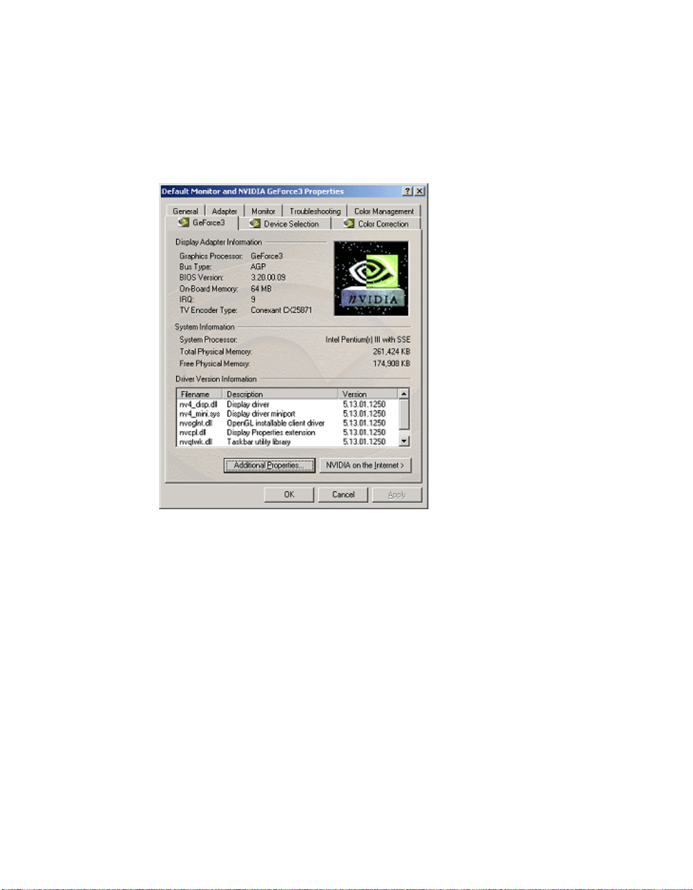
3 Click the Advanced button and then the GeForce3 tab to display the
GeForce3 control panel (Figure 3.1).
Figure 3.1
GeForce3 Control Panel
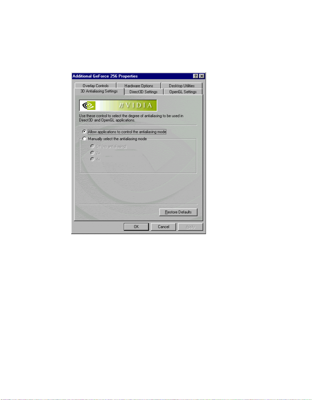
4
Click the Additional Properties button to display the 3D Antialiasing
control panel (Figure 3.2).
• For details on the 3D Antialiasing control panel, see “3D Antialiasing
• For details on the Direct3D Settings, click the Direct3D Settings tab and
• For details on OpenGL Settings, click the OpenGL Settings tab and see
• For details on the Overlay Contr ols panel, click the Overlay Controls ta b
• For details on the Desktop Utilities panel, click the Desktop Utilities tab
5 Click OK to return to the GeForce3 control panel.
NVIDIA Corporation
Settings” on page 138.
see “Direct3D Settings” on page135.
“OpenGL Settings” on page 130.
and see “Overlay Controls Panel” on page 140.
and see “Desktop Utilities” on page 125.
15
Page 26
Chapter 3 The GeForce3 Family of GPUs
• To access the Device Selection Panel, click the Device Selection tab and
see “Device Selection & Configuration” on page 79.
• To access the Color Correction panel, click Color Correction and see
“Color Correction Panel” on page 128.
Figure 3.2
3D Antialiasing Control Panel
16
NVIDIA Corporation
Page 27

Detonator XP User’s Guide
C HAPTER
4
T
WINVIEW
The NVIDIA TwinView architecture supports multiple displays on a
single dual-display graphics card based on the
(for laptops) or the Quadro2 MXR family of GPUs.
This chapter contains the following sections:
• “TwinView Display Device Options” on page 17
A
PPLICATIONS
GeForce2 MX, GeForce2 Go
• “TwinView Modes for Using Your Display Setup” on page 18
• “TwinView Applications” on page 19
TwinView Display Device Options
TwinView offers tremendous flexibility in how dual monitors are used. The
following sample display combinations:
• Two RGB monitors with second RAMDAC (
• Two analog flat panels
• Two digital flat panels (DFPs)
• One digital flat panel and one analog flat panel
• One digital flat panel and one RGB monitor
• One RGB monitor and one TV
• One RGB monitor and one analog flat panel (with second RAMDAC)
• One analog flat panel and one TV
Note: Actual combinations supported on a given card will vary.
digital-to-analog converter)
NVIDIA Corporation
17
Page 28

HAPTER
C
4 TwinView Applications
Setting up a dual-display graphics card involves installing the card on a PC,
attaching the two displ ay device s to th e PC, and i nstal ling t he cur rent v ers ion of
the NVIDIA Detonator XP driver. After rebooting the PC, the multiple display
modes of the graphics cards installed are fully functional.
For detailed information on using and configuring the TwinView options, see
the following chapters:
• “TwinView Basics: Windows 9x” on page 21
• “TwinView Basics: Windows XP/2000/NT 4.0” on page 45
TwinView Modes for Using Your Display Setup
The NVIDIA Unified Driver Architecture offers several modes for using
your display setup.
• Windows Multimonitor Support: In this mode, the desktop area is sprea d
across both displays. The refresh rate, color depth, and resolution may be
independently set for each display. You can set this mode for multiple
categories of displays, although display limitations may override the
capabilities of the TwinView-enabled graphics card. For example, if the
second display is a NTSC TV monitor, you won’t be able t o set t he resolu tion
above 800 x 600, nor set t he ref resh rate abo ve 60Hz due to the limit ations of
the monitor itself. However, the PC monitor in such a configuration may
have its refresh rate and resolution set much higher. The desktop may be
“stretched” horizontally or “stacked” vertically, depending on the user’s
needs. See “Extended Desktop: Windows 98/Me” on page 39 for Windows
9x or “Horizontal & Vertical Span Modes” on page 69 for Windows XP/
2000/NT 4.0.
18
• Application exclusive: The user may choose to dedicate an application to
one of the two monitors or run the application across both. Examples of this
include entertainment applications, digital video editing, and DVD playback.
• Clone mode: Two monitors may show exactly the same output, useful for
presentations. The pr esenter may have a small moni tor on the po dium while a
projector or presentation quality display shows the larger image to the
audience. (See “Clone Mode” on page 31 for Windows 9x or “Clone Mode”
on page 59 for Windows XP/2000/NT 4.0.)
• Application zoom mode: In this mode, part of the image from the primary
monitor is shown on the second ary di splay, b ut zoomed in . This mode can be
used for image editing, close-up work in modeling or CAD applications, or
image processing and mapping applications.
See “Desktop Manager” on page 105.
NVIDIA Corporation
Page 29

Detonator XP User’s Guide
• Virtual deskto p: Full support fo r vir tual d esktops is ava ilabl e for panels and
monitors with limited resolution. Virtual desktops, with full pan-and-scan
mode, can be configured for one or both displays.
See “Change Resolution: Clone Mode (Virtual Desktop)” on page 37 for
Windows 9x or “Change Resolution: Clone Mode (Virtual Desktop)” on
page 68 for Windows XP/2000/NT 4.0.
TwinView Applications
• Engineering or mechanical CAD applications can use multiple displays
for different directional views of an object or a building, such as a front or
side view or even a wiref ra me model on one screen and a textured version of
the same model on another. Many professional applications offer extensive
graphical user interfaces, which can be left fully enabled and visible on one
display, while the secon d display remai ns unobstruc ted for viewing t he actual
work.
• Training and Presentation: TwinView Clone mode, where two monitors
display identical images, is useful for presentations. A presenter may use the
smaller monitor on the podium , w hile a projector mo nitor reflects the
presentation to the audience. In training applications, the instructor can see
what the student is doin g under TwinVi ew Clone mode. The ability to see the
presentation while it's being projected can be especially useful in mobile
PCs.Virtual Desktop, a sub-feature of TwinView Clone Mode, is useful for
flat panels and monitors with limited resolution and is used to set a larger
than viewable area on the second display, which supports full pan-and-scan
of the entire desktop area.
• Digital content creation applications can use one display for toolbars and
palettes and the other for rendered output. Additionally, many real-time or
game development environments allow the authoring tools or game engine
code to be visible on one display, while showing the art or game engine in a
full screen, game play-like mode on the second display.
• Graphics Artists can have common applications such as Adobe Photoshop
or 3D Studio Max
other monitor dedicated to workspace. Writers can use one monitor for
research and the other for writing.
• Financial applications, such as stock trading applications, can use a pair of
large digital flat pan els . This would allow you to watch show real-time stoc k
data on one screen and use the other for trading activity. You can also use
two TwinView-enabled boards (on e AGP, one PCI) to hook up four displays.
• Video editing applications would use one large PC display and one NTSC
monitor. Since TwinView technology allows decoupling of refresh rates, the
NVIDIA Corporation
open with the palettes and menus on one monitor and the
19
Page 30

HAPTER
C
4 TwinView Applications
PC (editing) display coul d be a high-resolution RGB monitor for ru nni ng t he
application (Adobe Premiere, for example), while the second monitor can be
an NTSC or S-Video display for checking the video output for proper color
balance and quality.
• Entertainment applications can use multiple display support in several
ways. Game titles, such as Microsoft’s Flight Simulator 2000, support
multiple displays out of the box. With TwinView Clone mode, game play
can be sent to a big screen TV or even to a VCR.
• Home theater systems can take advantage of the DVD capabilities of your
PC. Simply hook up a large sc reen tel evision as you r seco nd monitor an d you
can watch DVDs -- without buying a dedicated DVD player. See Video
Mirror.
• Television and Mo vie s: Usi ng the TwinView Video Mirror feature, you can
watch TV and any other video while you work.
20
NVIDIA Corporation
Page 31

Detonator XP User’s Guide
C HAPTER
5
T
WINVIEW
To use the TwinView features you need a dual-display graphics card based on
one of the following NVIDIA GPUs:
• GeForce2 MX family
• GeForce2 Go (for laptops)
• Quadro2 MXR
B
ASICS
: W
INDOWS
9
X
TwinView offers the following display modes:
• “Standard Mode” on page 25
• “Clone Mode” on page 31
Note: Your NVIDIA GPU-based dual-display graphics card supports the
Windows Extended Desktop feature. To use this feature, see “Extended
Desktop: Windows 98/Me” on page 39.
This chapter assumes you have an analog monitor (CRT) and either a digital
flat panel (DFP) and/or a TV attached to your NVIDIA dual-display graphics
card. Follow the appropriate examples based on the display device(s) attached
to your computer.
Accessing the TwinView Panel
If you have only one displ ay d evi ce connected, the TwinView panel will only
have Standard (single-display) mode enabled and Clone mode disabled. In
single-display mode, you will not have TwinView Clone mode (Virtual
Desktop) and Video Mirror functionality and will have limited Desktop
Manager functionality. However, you can access the features available through
the Additional Properties button (see “Additional Features and
NVIDIA Corporation
21
Page 32

HAPTER
C
5 TwinView Basics: Windows 9x
Enhancements” on page 125) button on the NVIDIA GPU panel prov ided these
features are not depende nt on TwinView.
To access the TwinView panel when you have one display device attached,
you can follow the basic steps below, noting any exceptions, where
documented.
To access the TwinView control panel and both the Standard and Clone mode
features, follow these steps:
1
For dual-display functionality, be sure you have at least two display
devices, such as an analog monitor and a digital flat panel (DFP) or TV,
connected to your NVIDIA dual-display card.
2 Make sure the cable connections for your devices are well secured from the
device to the graphics card installed on your computer.
If you are connecting a TV, be sure you have the proper cables and
connectors that apply to your TV.
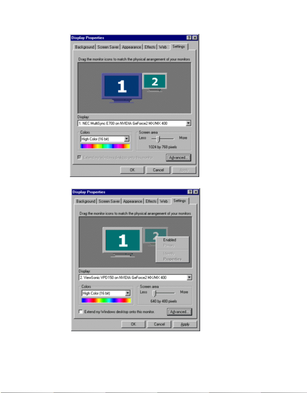
3 Right-click on your Windows desktop and then click Properties > Settings
tab to display the Settings panel (Figure 5.1). If you have only one display
device connected, go directly to step 7.
4 Be sure that the option “Extend my Windows desktop onto this monitor.” is
not checked.If the option is checked, follow these steps:
22
a Right-click monitor icon 2 to display the context menu.
b Click the checked Enable option to uncheck it (Figure 5.2).
5 Click Apply and then OK to leave the Settings panel.
6 Right-click on your Windows desktop, click Properties > Settings tab to
display the Settings panel again.
7 Click the Advanced button to display NVIDIA Properties panels (Figure
5.3).
8 Click the GeForce2 MX/MX 400 tab to display the GeForce2 MX.MX 400
control panel (Figure 5.4). This NVIDIA product panel provides basic
information about your di sp lay adapter, system, and the NVIDIA driver f il es
and versions you installed.
9 Click the TwinView tab to display the TwinView control panel (Figure 5.5).
NVIDIA Corporation
Page 33
Detonator XP User’s Guide
Figure 5.1
Figure 5.2
Display Properties Settings: Windows 98
Disabling Extended Desktop: Windows 98
NVIDIA Corporation
23
Page 34

HAPTER
C
5 TwinView Basics: Windows 9x
Figure 5.3
Figure 5.4
GeForce2 MX/MX 400 Properties Panels: Windows 98
GeForce2 MX Control Panel: Windows 98
24
NVIDIA Corporation
Page 35

Detonator XP User’s Guide
Accessing the Configuration Options
On the TwinView panel, the monitor icon numbered 1 represents the primary
display device. In Standard mode, there is only one monitor icon. In Clone
mode, the monitor icon numbered 1 represents the primary display device and
the monitor icon numbe red 2 represents the seconda ry displ ay device. To access
the configuration pa nels for Twi n View mod es, use any one of these procedure s:
• Click the moni tor i con (1 or 2) to display a context men u of opt ions a nd cli ck
the option you want; or
• Click the down arrow in the Display field to select the display device (i.e.,
TwinView Display 1 or TwinView Display 2 if you have multiple display
devices) you want to configu re. Then left -cli ck the Devic e Settings bu tt on to
display a context menu of options and select the option you want.
Standard Mode
The Standard mode option in the TwinView control panel disables the TwinView feature allowing viewing in only one display.
To access TwinView Standard mode,
1 Click the Standard option on the TwinView control panel
2 Click Apply.
Figure 5.5 shows analog monitor (CRT) as the primary display device (Display
1). If you have a DFP and/or a TV connected to your NVIDIA GPU-based
graphics card, you can choose to display on the DFP or TV instead of the CRT.
The next section explains how to switch between these devices.
Figure 5.6 shows a TwinView panel when only one display device, such as an
analog monitor (CRT), is attach ed. Not e tha t t he Clone mode option is disabled
in this case.
Note: Force detection of a monitor on the secondary connector is a check
box on the TwinView control panel and is normally disabled (graye d out)
as shown in Figure 5.5. Check this box if you have a monitor connected
to the secondary display connector that is not being detected. This is
useful for older monitors or monitors connected with BNC connectors.
NVIDIA Corporation
25
Page 36

HAPTER
C
5 TwinView Basics: Windows 9x
Figure 5.5
Figure 5.6
TwinView Std (dual-display) with Context Menu: Windows 98
TwinView S t d. Mode (single-disp lay) Context Menu: Windows 98
26
NVIDIA Corporation
Page 37

Detonator XP User’s Guide
Switching Display Device: Standard Mode
Primary Display
Figure 5.5 on the previous page shows TwinView Standard Mode with analog
monitor as the primary display; Primary Display is checked in the context
menu.
Select Output Device
Note: This secti on doe s not apply if you have only one display devi ce att ac hed.
Follow these steps to switch output devices in Standard mode:
1 Right-click the monitor icon to display the context menu (Figure 5.5) and
click Select Output Device to display the Device Selection panel. The
Device Selection pane l correct ly shows anal og monitor a s the selec ted output
device for this example.
Figure 5.7
TwinView Device Selection (Analog Monitor): Windows 98
Click the Digital Flat Panel option (Figure 5.8) or the TV option (Figure
2
5.9) and click Apply.
An NVIDIA display settings message appears, as shown in Figure 5.10
Figure 5.11.
NVIDIA Corporation
27
Page 38

HAPTER
C
5 TwinView Basics: Windows 9x
Figure 5.8
Figure 5.9
TwinView Device Selection (Digital Flat Panel): Windows 98
TwinView Device Selection (TV): Windows 98
28
NVIDIA Corporation
Page 39

Detonator XP User’s Guide
Figure 5.10
Click OK before the message times out.Your analog monitor screen will be
3
Switching Output Device Message: Windows 98
blank for a few seconds followed by a Confirm Desktop Settings message in
Figure 5.11, which shifts to your secondary display device (DFP or TV).
Figure 5.11
Click Yes to remove the message before it times out. The Device Selection
4
Switching Output Device Message: Windows 98
panel and your entire Windows desktop appears on the secondary display
device ( TV or DFP).
For DFP, the Digital Flat Panel option is enabled in the Device Selection
panel (Figure 5.12).
Figure 5.12
DFP Option Enabled on Digital Flat Panel Display: Windows 98
For TV, the TV option is enabled in the Device Selection panel (Figure
5.13).
NVIDIA Corporation
29
Page 40

HAPTER
C
5 TwinView Basics: Windows 9x
Figure 5.13
5
Click OK on the Device Selection panel to view the main TwinView panel
TV Option Enabled on TV Display: Windows 98
showing your DFP (Figure 5.14) or TV (Figure 5.15) as the Primary display.
Figure 5.14
TwinView Std. Mode (Display 1 = DFP): Windows 98
30
NVIDIA Corporation
Page 41

Detonator XP User’s Guide
Figure 5.15
To switch back to the CRT or DFP, you can follow the procedures in this
6
TwinView Std. Mode (Display 1 = TV): Windows 98
section, substituting either the Analog Monitor or the Digital Flat Panel
option on the Device Selection panel, as applicable.
Clone Mode
Note: This secti on doe s not apply if you have only one display devi ce att ac hed.
In Clone mode, two monitors display identical images, which is useful for
presentations. A presenter may use the smaller monitor on the podium, while a
projector monitor reflects the presentation to the audience.
Note: Under Clone mode, when you switch to full-screen Microsoft DOS
window or boot to a DOS prompt, the display is limited to the
primary display device.
The example in this secti on sta rts with th e anal og monit or (CRT) as th e prima ry
display.
1
To access TwinView Clone mode, click the Clone mode option on the
TwinView control panel and click Apply.
Your DFP display becomes enabled and you can see your current screen
duplicated on the clone (DFP) display.
NVIDIA Corporation
31
Page 42

HAPTER
C
5 TwinView Basics: Windows 9x
Figure 5.16 shows the TwinView Clone mode panel with the context menu
on the primary display (analog monitor). Figure 5.17 shows the TwinVie w
Clone mode panel with the context menu on the secondary display (DFP).
The Disable auto -panning on the Clone device (v ie wport lock) is added to
the control panel.(For details on using this option, see “Change Resolution:
Clone Mode (Virtual Desktop )” on page 37. To use the configuration options
in the context menu, proceed to the sections that follow
Figure 5.16
TwinView Clone Mode Menu (Display 1 = CRT): Windows 98
32
NVIDIA Corporation
Page 43

Detonator XP User’s Guide
Figure 5.17
2
To use the configuration option s in th e context menu, procee d to the sect ions
TwinView Clone Mode Menu (Display 2 = DFP): Windows 98
that follow.
Switching Secondary Displays : Clone Mode
Note: This example assumes the primary display is the analog monitor (CRT),
the DFP is the secondary display, and you are switching from DFP to TV. You
can use a similar procedure to switch from TV to DFP as the secondary display.
1 Right-click monitor icon 1 to view the context menu (Figure 5.16). Notice
that the Primary Display option is checked on the context menu and the
Display field indicates that the analog monitor is the primary display.
2 Right-click monitor icon 2 to view the context menu (Figure 5.17). Notice
that Primary Display is not checked on the context menu and the Display
field indicates that the digital flat panel is the secondary display.
3 If you have a TV connected and want to switch to TV as the secondary
display, right-click monitor icon 2 to access the context menu and choose
Select Output Device to display the Device Selection panel.
4 Select the TV option as shown in Figure 5.18 and click Apply. A message
appears indicating that Windows will switch your desktop to the selected
settings.
NVIDIA Corporation
33
Page 44

HAPTER
C
5 TwinView Basics: Windows 9x
5 Click OK to remove the message. Your analog monitor becomes blank for a
few seconds followed by a message titled Confirm Desktop Settings, which
Figure 5.18
TwinView Clone Device Selection TV Option: Windows 98
now switches to your secondary display device, the TV.
6 Click Yes to remove the message box. The Device Selection panel appears
on your TV display as shown in Figure 5.19.
Figure 5.19
TwinView Clone Device Selection Panel on TV: Windows 98
34
NVIDIA Corporation
Page 45

Detonator XP User’s Guide
7 Click OK to view the main TwinView panel showing your TV as the
secondary display (Figure 5.20).
Figure 5.20
TwinView Clone Mode (Display 2 = TV): Windows 98
Switching Secondary to Prim ary D isplay : Clone M ode
Note: The example in this section changes DFP or TV from a secondary to a
primary di splay.
1 Right-click monitor icon 2 (secondary display) to view the context menu.
2 Click Primary to check the option. The context menu is removed.
3 Click Apply. The NVIDIA Control Panel Exit Requirement message
appears.
4 Click OK to remove the message. The screen becomes blank for a few
seconds and the Settings panel appears.
5 Click the Advanced button and then the TwinView tab.
6 To verify that the DFP or TV is now the primary di spl ay, r ig ht- cl ick monitor
icon 1 to view the context menu.
Primary D i splay is checked on the context menu and the Display field
shows TwinView Display 1: Digit al Fl at Panel (Figure 5.21) or TwinView
Display 1: TV (Figure 5.22).
NVIDIA Corporation
35
Page 46

HAPTER
C
5 TwinView Basics: Windows 9x
Figure 5.21
Figure 5.22
TwinView Clone Mode (Display 1 = DFP): Windows 98
TwinView Clone Mode (Display 1 = TV): Windows 98
36
To verify that the analog monitor is now the secondary display, right-click
7
monitor icon 2 to view the context menu. The Primary option is not checked
NVIDIA Corporation
Page 47

Detonator XP User’s Guide
on the context menu and the Display field shows TwinView Display 2:
Analog Monitor (Figure 5.23).
Figure 5.23
TwinView Clone Mode (Display 2 = CRT): Windows 98
Change Resolution: Clone Mode (V irtual Des ktop)
You can use the Change Resolution option to modify Resolution and Refresh
Frequency for the secondary display, which allows you to enable Virtual
Desktop, a useful feature for panels and monitors with limited resolution. This
feature lets you pan-and-scan the entire desktop area on the secondary display,
when its resolution is set to less than the value set on the primary display.
Note: If the maximum resolution of the secondary display is less than the
current resolution of the primary display, once you enable Clone mode
from the TwinView panel, Virtual Desktop will already be enabled.
However, you still may want to adjust the resolutions of the primary and/
or secondary device by using the Device Configuration dialog box
(Figure 5.24) for the secondary display or the Windows Settings control
panel of your primary display.
Follow these steps to enable Virtual Desktop:
1 From the TwinView panel, right-click monitor icon 2 (secondary display) to
display the context menu and select Change Resolution to display the
Device Configuration dialog box (Figure 5.24).
NVIDIA Corporation
37
Page 48

HAPTER
C
5 TwinView Basics: Windows 9x
Note: If you do not see the Change Resolution option on the display 2
context menu, adjust (increase) the resolution of the primary display
until the Change Resoluti on option becomes availab le from t he displ ay
2 context menu.
Figure 5.24
Use the slider (Figure 5.24) to set the screen resolution to a value that is not
2
TwinView Clone Mode Device Configuration: Windows 98
equal to the screen re sol ut ion on t h e Wind ows Set ti ngs control panel of your
primary display.
Note: If you set the same screen resolution value for both primary and
secondary displays, you cannot use your secondary device for the
Virtual Desktop, i.e., to pan/scan the desktop; both displays will
remain static.
38
3 Optional: If you want, select a Refresh rate from the list box.
4 Click Apply and OK. Notice that the resolution of your secondary display
changes and you can use your mouse to pan and scan the desktop on this
secondary display.
5 If you want to lock the display position of the secondary display, check the
Disable auto-panning on the clone device (viewport lock) check box on
the TwinView panel (Figure 5.23).
NVIDIA Corporation
Page 49

Detonator XP User’s Guide
Extended Desktop: Windows 98/Me
The Windows Extended Desktop feature is supported by any dual-display
NVIDIA graphics card in the GeForce2 MX or Quadro2 MXR family of
products or any two NVIDIA graphics cards.
Note:
• Extended Desktop mode is not supported under Windows 95.
• Under Windows Extended Desktop mode, when you switch to a full-
screen Microsoft DOS window or boot to a DOS prompt, the display is
limited to the primary display device.
• Under Extended Desktop mode, OpenGL-b ased app licat ions wi ll onl y run
using Microsoft’s software rendering implementation of OpenGL. This is
due to a design limitation within Windows.
Follow these steps to enable Windows Extended Desktop mode:
1 Make sure you have two display devices attached to your dual-display card.
2 Right-click on your Windows desktop and click Properties > Settings tab.
You will see the Settings panel with two monitor icons, as shown in Figure
5.25.
Note: If you are using an NVIDIA dual-display card but have only one
display device connected (such as a CRT), you will see two monitor
icons on the Settings panel even though only one display device is
connected; you cannot enable the second display until you physically
connect a second display device to the graphics card.
3 Right click monitor icon 2 (Figure 5.26) a nd click Enable to check the option
(Figure 5.27).
Note: If you get a Compatibility Warning message, read the message
carefully. Then click OK
Notice that the “Extend my Windows desktop onto this monitor” check
box becomes checked (Figure 5.27).
4 Click Apply.
For details on configuring Extended Desktop, see “Configuring Extende d
Desktop” on page 42.
5 Click the Advanced button.
Notice that the TwinView tab is not available when Extended Desktop is
enabled (Figure 5.28).
NVIDIA Corporation
39
Page 50

HAPTER
C
5 TwinView Basics: Windows 9x
Figure 5.25
Figure 5.26
Display Settings: Windows 98
Enabling Extended Desktop (1): Windows 98
40
NVIDIA Corporation
Page 51

Detonator XP User’s Guide
Figure 5.27
Figure 5.28
Enabling Extended Desktop (2): Windows 98
TwinView Tab Disabled: Windows 98
NVIDIA Corporation
41
Page 52
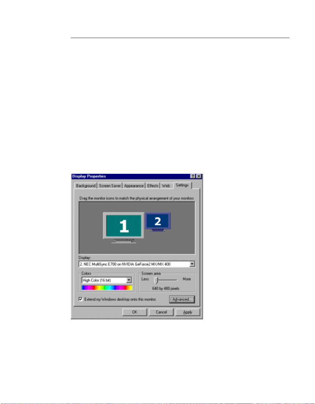
HAPTER
C
5 TwinView Basics: Windows 9x
Configuring Extended Desktop
In Windows Extended Desktop mode, the desktop area is spread across two
displays. This mode can be set for multiple categories of displays, although
display limitations may override the capabilities of your NVIDIA dual-display
graphics card. For example, if the second display is an NTSC TV monitor,
depending on the TV encoder on the graphics ca rd, the resolu tion may not be set
above 800 x 600 and the refresh rate cannot be set above 60 Hz. However, the
PC monitor in such a configuration may have its refresh rate and resolution set
much higher. The deskto p ca n be extended horizontally, verti cal l y, as wel l as a t
other angles by reposition ing the deskt op display ic ons in the Windows Sett ings
control panel.
You can drag the icons to the positions that represent how you want to move
items between monitors.
• For example, if you’re usi ng two monitor s and you want to move ite ms from
one monitor to the other by dragging left and right, position the icons
side-by-side (Figure 5.29).
Figure 5.29
Display Settings (Horizontal): Windows 98
42
• To move items between monitors by dragging up and down, position the
icons one above the other (Figure 5.30).
• To move items between monitors by dragging at an angle, position the
icons diagonally (Figure 5.31). The icon positions don’t have to correspond
NVIDIA Corporation
Page 53

Detonator XP User’s Guide
to the physical position s of your monitors . That is, you ca n position t he icons
one above the other even though your monitors are side-by-side.
Figure 5.30
Display Settings (Vertical): Windows 98
Figure 5.31
NVIDIA Corporation
Display Settings (Diagonal): Windows 98
43
Page 54

HAPTER
C
5 TwinView Basics: Windows 9x
Other Configuration Options
For details on configuring display devices and additional features and
enhancements of the Detonator XP driver, see the following chapters:
• “Device Selection & Configuration” on page 79.
• “Additional Features and Enhancements” on page 125.
44
NVIDIA Corporation
Page 55

Detonator XP User’s Guide
C HAPTER
6
T
WINVIEW
B
ASICS
:
To use the TwinView features you need a dual-display graphics card based on
one of the following NVIDIA GPUs:
• GeForce2 MX family
• GeForce2 Go (for laptops)
• Quadro2 MXR
TwinView offers the following display modes under Windows XP/2000/NT
4.0:
• “Standard Mode” on page 56
• “Clone Mode” on page 59
• “Horizontal & Vertical Span Modes” on page 69
Notes Before Y ou Begin
• This chapter assumes you have a CRT (analog monitor) and either a digital
flat panel (DFP) and/or a TV attached to your dual-display graphics card
that’s installed in your computer. Follow the appropriate examples,
depending on the display device(s) attached to your computer. (See “TV
Settings” on page 91 for information on configuring your TV display.)
INDOWS
W
XP/2000/NT 4.0
• Windows 2000 control panel screens also apply to Windows NT 4.0 and
XP; exceptions are noted where applicable.
NVIDIA Corporation
45
Page 56

HAPTER
C
6 TwinView Basics: Windows XP/2000/NT 4.0
Accessing the TwinView Panel: Windows XP
If you have only one displ ay d evi ce connected, the TwinView panel will only
have Standard (single-display) mode enabled and Clone mode disabled. In
single-display mode, you will not have TwinView Clone mode (Virtual
Desktop) and Video Mirror functionality and will have limited Desktop
Manager functionality. However, you can access the features available through
the Additional Properties button (see “Additional Features and
Enhancements” on page 125) on the NVIDIA GPU pane (Figure 6.3), provided
these features are not TwinView-dependent.
TwinView Enabled by Default (W indows XP SingleV iew)
1 Start up your Windows XP system installed with a TwinView capable dual-
display card connected to at least two display devices.
2 Right click on the desktop, click Properties and the Settings tab.The
Settings page appears with the dual monitor icons (Figure 6.1).
When you first enter Windows XP after installing and configuring your
system for TwinView, the Windows XP SingleView setting (second monitor
icon is greyed) is in effect, which allows you to access the TwinView panel.
Note: Windows XP DualView is disabled in this setting since it is not
compatible with TwinView Clone and Span mode. If you need to
enable DualView, see “Enabling DualView” on page 49.
3 Click the Advanced button to display the panel in Figure 6.2
4 Click the GeForce2 MX/MX 400 tab to display the GeForce2 MX panel,
which provides basic information on your display adapter, system, and the
NVIDIA driver files you installed (Figure 6.3).
5 Click the TwinView tab to display the TwinView control panel (Figure 6.4).
Windows XP DualView
Many modern display adapters are able to drive two or more different display
devices simultaneously. DualView in Windows XP provides system-level
support for features similar to those of Multimonitor but requires only a single
display adapter.
Note: The graphics device interfaces (GDIs) and what you view as the end-
user are identical for both DualView and Multimonitor.
46
NVIDIA Corporation
Page 57

Detonator XP User’s Guide
Figure 6.1
Figure 6.2
Display Properti es Settings: Windows XP
Advanced Options: Windows XP
NVIDIA Corporation
47
Page 58

HAPTER
C
6 TwinView Basics: Windows XP/2000/NT 4.0
Figure 6.3
Figure 6.4
GeForce2 MX Control Panel: Windows XP
TwinView Panel: Windows XP
48
NVIDIA Corporation
Page 59

Detonator XP User’s Guide
SingleView Mode
In SingleView mode, a display adapter dri ves a single display dev ice, regardles s
of the number of monitors. This is the usual mode for most of the display
adapters that Windows 2000 and later operating system versions currently
support.
DualView Mode
A computer in DualView mode can use a single display adapter (with multiple
video ports) to drive multiple images on different monitors, with each display
device portraying a different part of the desktop. The primary image displays
the primary view; other images display secondary views.
On a laptop computer, the primary display is always the LCD display screen.
On a desktop computer, the primar y displ ay does not have th is res tric tion. Once
you attach the second monitor and turn on your computer, use the Windows
Display Properties settings to configure your settings.
Enabling DualView
Follow these steps to enable Windows XP DualView:
Note: Currently, enabling dualview automatically disables the TwinView
feature.
1 Go to the Display Settings panel. (If you’re currently on the TwinView
panel, click OK to return to the Settings panel.)
2 Right click on the secondary monitor icon (numbered 2) Figure 6.5 and c li ck
the Attached option in the context menu that appears.
Notice that the Extend my Windows desktop. . checkbox becomes
checked.Figure 6.6.
3 Set the Color Quality to Highest (32 bit).
4 Click Apply.
NVIDIA Corporation
49
Page 60

HAPTER
C
6 TwinView Basics: Windows XP/2000/NT 4.0
Figure 6.5
Figure 6.6
Display Settings: Enabling DualView in Windows XP (1)
Display Settings: Enabling DualView in Windows XP (2)
50
NVIDIA Corporation
Page 61

Detonator XP User’s Guide
Configuring DualView Settings
The settings in the DualView Settings panel (Figure 6.6) are explained in this
section.
Note: Refer to the Windows XP online Help and documentation for further
information on using these settings.
•The monitor icons area displ ays a monitor icon for each mon itor atta che d to
your computer. If you are using just one monitor, that monitor shows the
relative size of items on your desktop, based on your current screen
resolution.
If you have more than one monitor installed, right-click a monitor icon, and
click Identify to see a number appear on the monitor corresponding to the
icon you clicked. The sett ings for that moni tor appear in Display, Color s, and
Screen Area.
If more than one icon is displayed, drag them to the positions that represent
how you want to move items between monitors. For example, if you are
using two monitors and you want to move items from one monitor to the
other by dragging left and right, position the icons side by side. To move
items between monitors by dragging up and down, position the icons one
above the other. The icon positions don’t have to correspond to the physical
positions of your monitors. You can position the icons one above the other
even though your monitors are side by side.
•The Display window displays all installed video adapters. If you are using
more than one monitor, the adapter for your primary monitor is in position 1.
• Screen resolution displays the current screen resolution settings for the
monitor whose video adapt er app ear s in the Display window. Drag the slider
to specify the screen resolution you want. As you increase the number of
pixels, you display more information on your screen, but the information
decreases in size.
• Color quality displays the current color settings for the monitor attached to
the video adapter t hat appear s in the Display window.To use a different color
settings, click the arrow, and then click a setting.
• Use this device as the primary monitor, when checked, specifies that the
monitor corresponding to the icon you se lected abov e is the primar y monitor.
The primary monitor will display the logon dialog box when you start your
computer. In addition, most programs will display windows on the primary
monitor when you initially open them.
Note: On a laptop computer, the primary display is always the LCD display
screen.
NVIDIA Corporation
51
Page 62

HAPTER
C
6 TwinView Basics: Windows XP/2000/NT 4.0
• Extend my Windows desktop onto this monitor, when checked, specifies
that your desktop will be extended onto the monitor corresponding to the
monitor icon you selected. This check box is unavailable for your primary
monitor because additional monitors are all extensions of the primary
monitor.
NVIDIA Panels With DualView Enabled
Click the Advanced button (Figure 6.6) to display the General page with
several NVIDIA tabs but without the TwinView tab, as shown in Figure 6.7.
For details on using the Device Selection panel, see “Accessing the Device
Selection Control Panel” on page 79.
For details on using the Color Correction panel, see “Color Correction Contro l
Panel” on page 129.
Figure 6.7
Non-TwinView NVIDIA Panels: Windows XP
52
NVIDIA Corporation
Page 63

Detonator XP User’s Guide
Accessing the TwinView Panel: Windows NT 4.0/2000
If you have only one displ ay d evi ce connected, the TwinView panel will only
have Standard (single-display) mode enabled and Clone mode disabled. In
single-display mode, you will not have TwinView Clone mode (Virtual
Desktop) and Video Mirror functionality and will have limited Desktop
Manager functionality. However, you can access the features available through
the Additional Properties button (see “Additional Features and
Enhancements” on page 125) on the NVIDIA GPU pane (Figure 6.10),
provided these features are not TwinView-dependent.
To access the TwinView control panel and all its modes, i.e, Standard, Clone,
and Span, follow these steps:
1
For dual-display functionality, be sure you have at least two display
devices, such as an analog monitor (CRT) and a digital flat panel (DFP) or
TV, connected to your NVIDIA dual-display card.
2 Make sure the cable connections for your devices are well secured from the
device to the graphics card installed on your computer.If you are connecting
a TV, be sure you have the proper cables and connectors that apply to your
TV.
3 Right-click from your Windows desktop and click Properties and the
Settings tab to display the Settings panel (Figure 6.8).
Figure 6.8
Display Properties Settings: Windows 2000
Click the Advanced button to display the panel in Figure 6.9 Click the
4
GeForce2 MX/MX 400 tab to display the GeForce2 MX panel, which
NVIDIA Corporation
53
Page 64

HAPTER
C
6 TwinView Basics: Windows XP/2000/NT 4.0
provides basic information about your display adapter, system, and the
NVIDIA driver files you installed (Figure 6.10).
Figure 6.9
Advanced Options: Windows 2000
54
Figure 6.10
GeForce2 MX Control Panel: Windows 2000
NVIDIA Corporation
Page 65

Detonator XP User’s Guide
5 Click the TwinView tab to display the TwinView control panel.
Figure 6.11
TwinView: Std. Mode (singl e-dis pl ay) wit h C ont ex t Menu: Windows 2000
Accessing the Configuration Options
On the TwinView panel, the monitor icon numbered 1 represents the primary
display device. In Standard mode, there is only one monitor icon. In Clone
mode, the monitor icon numbered 1 represents the primary display device and
the monitor icon numbered 2 represents the secondary display device.
To access the configuration panels for Twin View modes, use any one of these
procedures:
• Right-cl ick the m onitor i con (1 or 2) to displ ay a contex t menu of op tions and
click the option you want; or
• Click the down arrow in the Display field to select the display device (i.e.,
TwinView Display 1 or TwinView Display 2) you want to configure. Then
click the Device Settings button to display a context menu of options and
click the option you want.
NVIDIA Corporation
55
Page 66

HAPTER
C
6 TwinView Basics: Windows XP/2000/NT 4.0
Standard Mode
Note: The Windows 2000 NVIDIA control pa nel screens shown in this
document also apply to Windows NT 4.0 and XP; exceptions are noted,
where applicable.
The Standard mode option in the TwinView control panel disables the TwinView feature allowing viewing in only one display. Figure 6.12 shows a
TwinView panel when only one display device (e.g, Analog Monitor) is
connected to your computer. Notice that the Clone mode option is disabled.
Figure 6.12
TwinView: Std. Mode (singl e-dis pl ay) wit h C ont ex t Menu: Windows 2000
56
Figure 6.13 shows the TwinView control panel in Standard mode with Analog
Monitor (CRT) as the Primary display device (Display 1). If you have a DFP
and/or a TV connected to your dual-display graphics card, you can choose to
display on the DFP or TV instead of the CRT.
NVIDIA Corporation
Page 67

Detonator XP User’s Guide
Figure 6.13
TwinView: Std. Mode (dual-display) with Context Menu
Switching Display Device: Standard Mode
To switch devices from Analog Monit or ( CRT) to either a DFP or a TV display
device, or variations on this combination, see “Switching Displays” on page 83
in the chapter “Device Selection & Configuration” on page 79.
The figures in this section show the TwinView panel in Standard mode with
either a DFP or TV as the display device.
NVIDIA Corporation
57
Page 68

HAPTER
C
6 TwinView Basics: Windows XP/2000/NT 4.0
Figure 6.14
Figure 6.15
TwinView Std. Mode (Display =TV): Windows 2000
TwinView Std. Mode (Display =DFP): Windows 2000
58
NVIDIA Corporation
Page 69

Detonator XP User’s Guide
Clone Mode
Note: Clone Mode does not wor k if yo u have on ly one display device attached.
Note: The Windows 2000 NVIDIA control panel screens shown in this
document also apply to Windows NT 4.0 and Windows XP; exceptions
are noted, where applicable.
In Clone mode, two monitors display identical images, which is useful for
presentations. A presenter may use the smaller monitor on the podium, while a
projector monitor reflects the presentation to the audience.
The example in this section starts with the Analog Monitor (CRT) as the
primary display and TV or DFP as the secondary display. Make sure your
display devices are powered on before you access the TwinView panel. If you
power on the devices after you have opened the TwinView panel, click Detect
Displays to enable the devices.
To access TwinView Clone mode, follow these steps:
1 Be sure your display devices are powered on before you access the
TwinView panel.
2 Click the Clone mode option on the TwinView control panel and click
Apply.
3 Click OK and Yes when the status messages appear. Your current screen is
duplicated on the clone display.
4 If necessary, click Detect Displays to enable devices. Figure 6.16 shows a
TwinView Clone mode control panel.
5 Right-click monitor icon 1 to view the context menu for the primary display,
which is CRT (analog monitor) in this example (Figure 6.16).
6 From the context menu, click Select Output Device to selec t the Device
Selection panel. Figure 6.17 correctly shows Analog Monitor as the selected
output device for display 1.
7 Click OK to return to the TwinView control panel.
8 Click monitor icon 2 to view the secondary display. Fi gure 6.18 shows TV as
the secondary display. Figure 6.19 shows DFP as the secondary display.
9 Clic k the Select Output Device button to display the Device Selection
control panel.
Figure 6.20 shows T V as the sel ected output devi ce f or t he se cond ary d ispla y
(display 2). For information on configuring your TV display, see “TV
Settings” on page 91.
NVIDIA Corporation
59
Page 70

HAPTER
C
6 TwinView Basics: Windows XP/2000/NT 4.0
Figure 6.21 shows Digital Flat Panel as the selected output device for the
secondary display (display 2).
Figure 6.16
TwinView Clone Mode (Display 1=Analog Monitor): Windows 2000
60
Figure 6.17
TwinView Device Selection (Display 1=Analog Monitor): Windows 2000
NVIDIA Corporation
Page 71

Detonator XP User’s Guide
Figure 6.18
Figure 6.19
TwinView Clone Mode Menu (Display 2=TV): Windows 2000
TwinView Clone Mode Menu (Display 2=DFP): Windows 2000
NVIDIA Corporation
61
Page 72

HAPTER
C
6 TwinView Basics: Windows XP/2000/NT 4.0
Figure 6.20
Figure 6.21
TwinView Output Device (Display 2=TV): Windows 2000
TwinView Device Selection Panel on DFP display: Windows 2000
62
NVIDIA Corporation
Page 73

Detonator XP User’s Guide
Switching Secondary Displays : Clone Mode
Note: The example in this section uses TV as the secondary display device and
describes how to switch from TV to Digital Flat Panel. You can use a
similar procedure to switch from DFP to TV.
1 Right-click monitor icon 2 to view the context menu for the secondary
display, which is TV in this example (Figure 6.22).
Figure 6.22
TwinView Clone Mode Menu (Display 2=TV): Windows 2000
2
From the context menu, cl ick Device Selectio n to selec t the De vice Sele ction
panel. Figure 6.23 correctly shows TV as the selected output device for
display 2 (secondary display).
For details on configuring TV settings, see “TV Settings” on page 91.
3 Click Digital Flat Panel, as shown in Figure 6.24.
4 Click Apply. The NVIDIA Display Settings message panel appears (Figure
6.25).
5 Click OK before the message times out. The Confirm Display Settings
message (Figur e 6.26) and the rest of your Windows desktop a ppears on y our
DFP display.
NVIDIA Corporation
63
Page 74

HAPTER
C
6 TwinView Basics: Windows XP/2000/NT 4.0
Figure 6.23
Figure 6.24
TwinView Output Device (Display 2=TV): Windows 2000
TwinView Output Device (Display 2=DFP): Windows 2000
64
NVIDIA Corporation
Page 75

Detonator XP User’s Guide
Figure 6.25
Figure 6.26
6
Click Yes before the message times out. The Device Selection panel appe ar s
TwinView Settings Change Message: Windows 2000
TwinView Confirm Display Settings Message: Windows 2000
with Digital Flat Panel selected, as shown in Figure 6.27.
7 Click OK to display the TwinView Clone mode panel showing Digital Flat
Panel as the secondary display. Figure 6.28 shows TwinView Clone mode
panel with the context menu for the Digital Flat Panel display.
Figure 6.27
TwinView Device Selection panel on DFP display: Windows 2000
NVIDIA Corporation
65
Page 76

HAPTER
C
6 TwinView Basics: Windows XP/2000/NT 4.0
Figure 6.28
TwinView Clone Mode Menu (Display 2=DFP): Windows 2000
Switching Secondary to Prim ary D isplay : Clone M ode
66
Note: The example in this section changes DFP from a secondary to a primary
display.You can use a similar procedure to change TV from a secondary
to a primary display.
1 Make sure you have the TwinView panel open in Clone mode and DFP
selected as display 2.
2 Right-click monitor icon 2 to display the context menu.
3 Select Primary Display. The “Make this the primary display” box becomes
checked.
4 Click Apply. The NVIDIA Display Settings message appears.
5 Click OK before the message times out.
The Confirm Display Settings message and the rest of your Windows
desktop appears on your DFP display.
6 Click Yes before the message times out.
When the TwinView panel appears, Digital Flat Panel is enabled as the
primary display device (Figure 6.29).
NVIDIA Corporation
Page 77

Detonator XP User’s Guide
Figure 6.29
Right-click monitor icon 2 to confirm that the CRT (analog monitor) is now
7
TwinView Clone Mode (Switching DFP to Primary): Windows 2000
the secondary device (Figu re 6.30).
Figure 6.30
TwinView Clone Mode (Display 2 = Analog Monitor): Windows 2000
NVIDIA Corporation
67
Page 78

HAPTER
C
6 TwinView Basics: Windows XP/2000/NT 4.0
8 You can use similar steps as described in this section to switch to TV as the
primary display (Figure 6.31).
Figure 6.31
TwinView Clone Mode (Display 1 = TV): Windows 2000
68
Change Resolution: Clone Mode (V irtual Des ktop)
You can use the Change Resolution option to modify Resolution and Refresh
Frequency for the secondary display, which allows you to enable Virtual
Desktop, a useful feature for panels and monitors with limited resolution. This
feature lets you pan-and-scan the entire desktop area on the secondary display
when its resolution is set to less than the value set on the primary display.
Note: If the maximum resolution of the secondary display is less than the
current resolution of the primary display, once you enable Clone mode
from the TwinView panel, Virtual Desktop will already be enabled.
However, you still may want to adjust the resolutions of the primary and/
or secondary device by using the Device Configuration dialog box
(Figure 6.32) for the secondary display or the Windows Settings control
panel of your primary display.
Follow these steps to enable Vir tual Desktop:
NVIDIA Corporation
Page 79

Detonator XP User’s Guide
1 From the TwinView panel, right-click monitor icon 2 (secondary display) to
display the context menu and select Change Resolution to display the
Device Configuration dialog box (Figure 6.32).
Note: If you do not see the Change Resolution option on the display 2
context menu, adjust (increase) the resolution on the primary display
until the Change Resoluti on option becomes availab le from t he displ ay
2 context menu.
Figure 6.32
2
Use the slider (Figure 6.32) to set the screen resolution at a value that is not
TwinView Clone Mode Device Configuration: Windows 98
equal to the screen re sol ut ion on t h e Wind ows Set ti ngs control panel of your
primary display.
Note: If you set the same screen resolution value for both primary and
secondary displays, you cannot pan/scan the desktop area on the
secondary display; both displays will remain static.
3 Optional: If you want, you can select a Refresh rate from the list box
4 Click Apply and OK. Notice that the resolution of your secondary display
changes and you can use your mouse to pan and scan the desktop on this
secondary display.
Horizontal & V ertical Span Modes
Note: Span modes do not work if you have only one display device attached.
Note: The Windows 2000 NVIDIA control panel screens shown in this
document also apply to Windows NT 4.0 and Windows XP; exceptions
are noted, where applicable.
In Span mode, the Windows deskt op a re a i s spread across both display de vic es.
This mode can be set for multiple categories of displays, although display
limitations may overri de the capabi liti es of y our NVID IA dual -disp lay gra phics
card. For example, if th e se cond display is an NTSC TV monitor, depending on
the TV encoder on the graphics card, the resolution may not be set above 800 x
NVIDIA Corporation
69
Page 80

HAPTER
C
6 TwinView Basics: Windows XP/2000/NT 4.0
600 and the refresh rate cannot be set a bove 60 Hz. Howe ver, the PC moni tor in
such a configuration may have its refresh rate and resolution set much higher.
The desktop may be “stretched” horizont ally or “s tack ed” vert ical ly, dependi ng
on user needs.
Due to operating system differences between Windows 9x and Windows NT
4.0/Windows 2000, the latter does not currently offer true multi-monitor
support for Span mode using one NVIDIA dual-display graphics card
1
. As a
result, the size of the actual desktop is limited to twic e the smaller size of th e
two displays.
Note: The desktop can be extended either horizontally (Figure 6.33 through
Figure 6.37) or vertically (Figure 6.40 and Figure 6.43).
To access the TwinView Span modes, follow these steps:
1 Click the Horizontal or Vertical Span mode option on the TwinView
control panel and click Apply.
2 Click OK and Yes when the messages appear.
• If you just switched from Standa rd to one of the Sp an modes, you r DFP or
TV display will be activated. If needed, click Detect Displays to enable
the display devices.
• If you just switched from Clone to one of the Span modes, the Windows
display on the Clone device will be removed.
70
3 Depending on whether you have Horizontal or Vertical Span mode enabled,
you can drag your active windo ws, images, or icons hor izontall y or vertical ly
to move them to the secondary display.
Switching Display Device: Span Modes
The basic procedure for switching devices in Span modes is the same as that
used in Clone mode. The figures in this section include configurations where
Analog Monitor, Digital Flat Panel, or TV is set as either the primary or
secondary display. You can use the following basic steps below to switch to a
different primary or secondary device.
1 Make sure your TwinView panel is set to Horizontal Span or Vertical Span
mode.
2
To switch a display device from secondary to primary, follo w these step s:
a Right-click monitor icon 2.
b Click Primary Display to check the option. The “Make this the primary
display” checkbox displays a check mark to reflect the primary display.
1. If two graphics cards are installed, the Windows 2000 operating system does detect two devices
NVIDIA Corporation
Page 81

Detonator XP User’s Guide
c Click the Apply button.
d When the NVIDIA Display Settings message appears, click OK. The
TwinView control panel now appears on the secondary device. The
TwinView Display field shows “TwinView Display 1: Digital Fl at Panel”,
which correctly indicates that the Digital Flat Panel is now the primary
display.
e To switch back to CRT as the primary display, follow similar steps.
3
To switch from TV to DFP, or vice versa, follow these steps:
a Right-click monitor icon 2 or 1, depending on whe ther the TV/DFP is your
primary or secondary device.
b From the context menu, click Select Output Device to select the Device
Selection panel.
c Click Digital Flat Panel or TV, depending on the device to which you
want to switch.
d Click Apply. The NVIDIA Display Settings message appears.
e Click OK before the message times out. The Confirm Display Settings
message and the rest of your Windows desktop appears on your newly
selected display (TV or DFP).
4 Click Yes before the message times out . The Devic e Sel ect ion panel appears
with Digital Flat Panel selected.
5 Click OK to display the TwinView Horizontal Span or Vertical Span mode
panel showing DFP or TV a s the seco ndar y or prima ry di splay, depen ding o n
the display you were working with.
6 Right-click the monitor icon (1 or 2) to confirm correct results.
NVIDIA Corporation
71
Page 82

HAPTER
C
6 TwinView Basics: Windows XP/2000/NT 4.0
Figure 6.33
Figure 6.34
TwinView Horizontal Span (Display 1= CRT): Windows 2000
TwinView Horiz. Span (Display 1= CRT) Context Menu: Windows 2000
72
NVIDIA Corporation
Page 83

Detonator XP User’s Guide
Figure 6.35
Figure 6.36
TwinView Horizontal Span Menu (Display 2 = DFP): Windows 2000
TwinView Horizontal Span Menu (Display 2 = CRT): Windows 2000
NVIDIA Corporation
73
Page 84

HAPTER
C
6 TwinView Basics: Windows XP/2000/NT 4.0
Figure 6.37
Figure 6.38
TwinView Horizontal Span (Display 1= DFP): Windows 2000
TwinView Horizontal Span (Display 2= TV): Windows 2000
74
NVIDIA Corporation
Page 85

Detonator XP User’s Guide
Figure 6.39
Figure 6.40
TwinView Horizontal Span (Display 1= TV): Windows 2000
TwinView Vertical Span Menu (Display 1 = CRT): Windows 2000
NVIDIA Corporation
75
Page 86

HAPTER
C
6 TwinView Basics: Windows XP/2000/NT 4.0
Figure 6.41
Figure 6.42
TwinView Vertical Span Menu (Display 1 = TV): Windows 2000
TwinView Vertical Span Menu (Display 1 = DFP): Windows 2000
76
NVIDIA Corporation
Page 87

Detonator XP User’s Guide
Figure 6.43
TwinView Vertical Span Menu (Display 2 = CRT): Windows 2000
Other Configuration Options
For details on configuring disp la y d evices, such as a TV, see “Device Selection
& Configuration” on page 79.
For details on configuring additional features, see “Additional Features and
Enhancements” on page 125.
NVIDIA Corporation
77
Page 88

HAPTER
C
6 TwinView Basics: Windows XP/2000/NT 4.0
78
NVIDIA Corporation
Page 89

Detonator XP User’s Guide
C HAPTER
7
D
EVICE
This chapter contains the following sections:
• “Accessing the Device Selection Control Panel” on page 79
• “Switching Displays” on page 83
• “Device Adjustments: Analog Monitor” on page 85
S
ELECTION
& C
ONFIGURATION
• “Device Adjustments: Digital Flat Panel” on page 87
• “TV Settin gs” on page 91
Note: Windows 2 000 cont rol pan el scree ns also apply t o Windows NT 4.0 and
XP; exceptions are noted where applicable.
Accessing the Device Selection Control Panel
Note: This ch apt er as sumes t hat you have at least a dual-display NVIDIA GPU-
based card and you have at least two display devices connected to your
card. You can use the basic procedure described here to switch between
any devices that are connected.
1 Right-click from your Windows desktop and click Properties and the
Settings tab to display the Settings panel (Figure 7.1).
2 Click the Advanced button.
3 Click the Device Selection tab to display the Device Selection panel. This
example uses the GeForce3 GPU-based card (Figure 7.2) with Analog
Monitor (CRT) enabled.
4 Click Detect Displays if you want to detect all display devices connected to
the output device (Analog Monitor, Digital Flat Panel, or TV) that is enabled
NVIDIA Corporation
79
Page 90

HAPTER
C
7 Device Selection & Configuration
on the Device Selection panel. Use this feature if you have plugged in any
displays after this Device Selection control panel was opened.
Figure 7.1
Display Properties Settings
Figure 7.2
Device Selection (Single Display)
80
NVIDIA Corporation
Page 91

Detonator XP User’s Guide
Figure 7.3
Figure 7.4
Device Selection CRT (TwinView)
Device Selection DFP (TwinView)
NVIDIA Corporation
81
Page 92

HAPTER
C
7 Device Selection & Configuration
Figure 7.5
Figure 7.6
Device Selection TV (TwinView)
Device Selection: Windows XP DualView Enabled
82
NVIDIA Corporation
Page 93

Detonator XP User’s Guide
Switching Displays
This section explains the procedure for switching the display from your CRT
(analog monitor) to a DFP using the example of a GeForce3 GPU-based
graphics card with three connectors:
• CRT (analog monitor)
• DFP (digital flat panel) and
• TV
This means that the user of such a graphics card can choose to connect three
different devices and switch among them or simply connect one of the devices
and use that device. Your GeForce3 GPU-based graphics card or any other
multi-connector NVIDIA GPU-based card may have anywhere between one
and three connectors. So, you’ll need to follow the example based on the
number and type of connectors your card contains.
Note: You can use the procedure in this section to switch between any
combination of devices, such as CRT to TV, TV to CRT, DFP to CRT,
TV to DFP, and so on. You can also use other NVIDIA GPU-based cards,
such as the GeForce2 MX, Quadro2 MXR, and so on. In this case, you’ll
notice that the NVIDIA product tab names of GeForce3, Device
Selection, and Color Correc tion do not exi st if , for exa mple, you have the
TwinView feature enabled.
1 Make sure you are in the Device Selection panel. (See the previous section
“Accessing the Device Selection Control Panel” on page 79, if needed.)
2 If you are using an NVIDIA GPU from the GeForce2 MX/Quadro2 MXR
family and have TwinView enabled, on the TwinView control panel, rightclick the monitor icon to display the context menu and click Select Output
Device to display the Device Selection control panel.
3 Click the Digital Flat Panel Option as shown in Figure 7.7 and click Apply.
The message in Figure 7.8 appears.
4 Click OK before the message times out. The Confirm Display Settings
message in Figure 7.9 appears on your DFP display.
5 Click Yes before the message times out. Your TwinView and entire
Windows display now shifts to the or DFP (Figure 7.10).
NVIDIA Corporation
83
Page 94

HAPTER
C
7 Device Selection & Configuration
Figure 7.7
Figure 7.8
Device Selection with DFP Selected
Display Settings Message: Windows 2000
84
Figure 7.9
Confirm Display Settings Message: Windows 2000
NVIDIA Corporation
Page 95

Detonator XP User’s Guide
Figure 7.10
Device Selection with DFP Enabled
Device Adjustments: Analog Monitor
Screen Adjustment
If your NVIDIA graphics car d is connected to a CRT (Analog Monitor), follow
these steps to access the Screen Adjustment panel:
Note: If you are in the TwinView control pan el, right-click the Analog Mon it or
icon to display the context menu and select Screen Adjustment to
display the Screen Adjustment panel. Then go directly to step. 4 below.
1 Make sure you are in the Device Selection panel. (See the earlier section
“Accessing the Device Selection Control Panel” on page 79, if needed.)
2 Confirm that the Analog Monitor option is s ele ct ed on t he Device Selection
panel.
3 Click the Device Adjustments but ton to a ccess t he Scre en Adjus tment pa nel
(Figure 7.11).
4 To adjust the screen position, move the mouse ov er the monitor ic on and drag
the desktop to the desired position while holding down the primary mouse
button. Use the arrow positioning buttons for fine adjustments.
NVIDIA Corporation
85
Page 96

HAPTER
C
7 Device Selection & Configuration
Figure 7.11
Screen Adjustments (Analog Monitor): Windows 2000
Display Timi ng
86
If your NVIDIA graphics car d is connected to a CRT (Analog Monitor), follow
these steps to access the Display Timing panel:
Note: If you are in the TwinView control pan el, right-click the Analog Mon it or
icon to display the context menu and select Screen Adjustment to
display the Screen Adjustment panel. Then click the Display Timing tab
to open the Display Timing panel and go directly to step. 4 below.
1 Make sure you are in the Device Selection panel. (See the earlier section
“Accessing the Device Selection Control Panel” on page 79, if needed.)
2 Confirm that the Analog Monitor option is s ele ct ed on t he Device Selection
panel.
3 Click the Device Adjustments button then click the Display Timing tab to
open the Display Timing panel.
NVIDIA Corporation
Page 97

Detonator XP User’s Guide
Figure 7.12
Select the proper timing mode for your display:
4
•
Display Timing (Analog Monitor): Windows 2000
Auto-Detect (default setting) allows Windows to receive the proper
timing information directly from the monitor itself. Note that some older
monitors may not support this feature.
•
General Timing Formula (GTF) is a standard used by most newer
hardware.
•
Discrete Monitor Timings (DMT) is an older standard still in use on
some hardware. Enable this option if your hardware requires DMT.
Device Adjustments: Digital Flat Panel
Flat Panel Display
If your NVIDIA graphics card is conne cte d to a DFP (di gi ta l fl at panel ), f oll ow
these steps to access the Flat Panel Display control panel.
Note: If you are in the TwinView control panel, right-click the Digital Flat
Panel icon and select Screen Adjustment to display the Flat Panel
Display control panel. Then go directly to step. 4 below.
1 Make sure you are in the Device Selection panel. (See the previous section
“Accessing the Device Selection Control Panel” on page 79, if needed.)
NVIDIA Corporation
87
Page 98
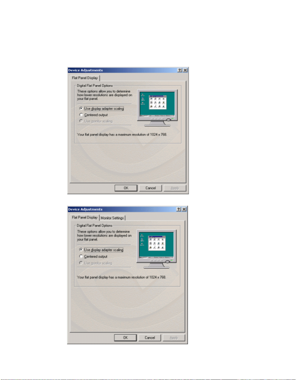
HAPTER
C
7 Device Selection & Configuration
2 Confirm that the Digital Flat Panel option is selected on the Device
Selection panel.
3 Click the Device Adjustments button to access the Flat Panel Display
control panel (Figure 7.13)
Figure 7.13
Digital Flat Panel Display as Display 1: Windows 2000
88
Figure 7.14
Digital
Flat Panel Display as Display 2: Windows 2000
NVIDIA Corporation
Page 99

Detonator XP User’s Guide
4 You can use the options Use display adapt er scaling and Centered Output
to determine the placement of the image on your flat panel display when
running at resolutions lower than the maximum supported resolution.
Figure 7.15
Digital Flat Panel Display - Centered Output: Windows 2000
Note: The Use monitor scaling option is available for flat panels that support
Monitor Settings (Refr esh Fr equency ): Sec ondary Display
Note: The Monitor Settings option only appears for the secondary display
Follow these steps to modify the Refresh Frequency of your secondary display
device:
Note: If you are in the TwinView control panel, right-click the Digital Flat
1 Make sure you are in the Device Selection panel. (See the earlier section
“Accessing the Device Selection Control Panel” on page 79, if needed.)
NVIDIA Corporation
multiple native resolutions.
device (Display 2), if the secondary device is a DFP or CRT (analog
monitor). In this example, the secondary display device is a DFP.
Panel icon and select Screen Adjustment to display the Flat Panel
Display control panel, click Monitor Settings to open the Monitor
Settings panel, then go directly to step. 4 below.
89
Page 100

HAPTER
C
7 Device Selection & Configuration
2 Confirm that the Digital Flat Panel option is selected on the Device
Selection panel.
3 Click the Device Adjustments button to access the Flat Panel Display
control panel.
4 Click Monitor Settings to open the Monitor Settings panel (Figure 7.16).
Figure 7.16
Monitor Setting for DFP as Display 2: Windows 2000
90
Note: The Monitor Settings panel in Figure 7.16 resemble s the Monitor pa nel
for your primary display (Properties > Settings tab > Advanced
button > Monitor tab) but actually represents your secondary display.
The Refresh Frequency list box lists the refresh rates available for this
monitor. You may select a different refresh rate than the one that appears in
the list box. A higher refresh frequency reduces flicker on your screen.
Note: It is recommend that you keep the Hide modes that this monitor
cannot display option c hec ked. Un che cki ng t he o p ti on wil l a ll ow you
to set your dis pl ay to modes that this monitor c ann ot display correctly,
which may lead to an unusable displ ay an/or damaged ha rdware . Also,
unchecking this option will prevent enabling TwinView Span modes.
NVIDIA Corporation
 Loading...