

Page 1
Model
HC101B
Owner’s Manual &
Safety Instructions
Battery and Charger Sold Separately
20V/120V Dual Power LED Work Light
WARNING: To prevent serious injury, User must read and
understand Owner’s Manual. SAVE THIS MANUAL.
When unpacking, make sure that the product is intact and
undamaged. If any parts are missing or broken, please call
1-888-866-5797 as soon as possible. Reference
57147.
Page 2

IMPORTANT SAFETY INFORMATION
GENERAL POWER TOOL SAFETY WARNINGS
Read all safety warnings and all instructions.
Failure to follow the warnings and instructions may
result in electric shock, fire and/or serious injury. Save
all warnings and instructions for future reference.
The term ″power tool″ in the warnings refers to your
battery-operated (cordless) mains-operated (corded)
power tool.
Work Area Safety
1. Keep work area clean and well lit.
Cluttered or dark areas invite accidents.
2. Do not operate power tools in explosive
atmospheres, such as in the presence of
flammable liquids, gases or dust. Power tools
create sparks which may ignite the dust or fumes.
3. Keep children and bystanders
away while operating a power tool.
Distractions can cause you to lose control.
Electrical Safety
1. Power tool plugs must match the outlet.
Never modify the plug in any way.
Do not use any adapter plugs with earthed
(grounded) power tools. Unmodified plugs and
matching outlets will reduce risk of electric shock.
2. Avoid body contact with earthed or grounded
surfaces such as pipes, radiators, ranges and
refrigerators. There is an increased risk of electric
shock if your body is earthed or grounded.
3. Do not expose power tools to rain or wet
conditions. Water entering a power tool
will increase the risk of electric shock.
4. Do not abuse the cord. Never use the cord for
carrying, pulling or unplugging the power tool.
Keep cord away from heat, oil, sharp edges
or moving parts. Damaged or entangled
cords increase the risk of electric shock.
5. When operating a power tool outdoors,
use an extension cord suitable for
outdoor use. Use of a cord suitable for outdoor
use reduces the risk of electric shock.
6. If operating a power tool in a damp location
is unavoidable, use a Ground Fault Circuit
Interrupter (GFCI) protected supply.
Use of a GFCI reduces the risk of electric shock.
Personal Safety
1. Stay alert, watch what you are doing and use
common sense when operating a power tool.
Do not use a power tool while you are tired
or under the influence of drugs, alcohol or
medication. A moment of inattention while operating
power tools may result in serious personal injury.
2. Use personal protective equipment. Always wear
eye protection. Protective equipment such
as dust mask, non-skid safety shoes, hard hat,
or hearing protection used for appropriate
conditions will reduce personal injuries.
3. Prevent unintentional starting. Ensure the Switch
is in the off-position before connecting to
power source, picking up or carrying the tool.
Carrying power tools with your finger on
the Switch or energizing power tools that
have the Switch on invites accidents.
4. Do not overreach. Keep proper footing and
balance at all times. This enables better control
of the power tool in unexpected situations.
5. Dress properly. Do not wear loose clothing or
jewelry. Keep your hair, clothing and gloves
away from moving parts. Loose clothes, jewelry
or long hair can be caught in moving parts.
6. If devices are provided for the connection of
dust extraction and collection facilities, ensure
these are connected and properly used. Use of
dust collection can reduce dust-related hazards.
7. Only use safety equipment that has been
approved by an appropriate standards agency.
Unapproved safety equipment may not provide
adequate protection. Eye protection must be
ANSI-approved and breathing protection
must be NIOSH-approved for the
specific hazards in the work area.
Power Tool Use and Care
1. Do not force the power tool. Use the
correct power tool for your application.
The correct power tool will do the job better and
safer at the rate for which it was designed.
2. Do not use the power tool if the Switch
does not turn it on and off. Any power tool
that cannot be controlled with the Switch
is dangerous and must be repaired.
Page 2 For technical questions, please call 1-888-866-5797. Item 57147
Page 3

3. Disconnect the plug from the power source
and/or remove the battery pack, if detachable,
from the power tool battery pack from the
power tool before making any adjustments,
changing accessories, or storing power
tools. Such preventive safety measures reduce
the risk of starting the power tool accidentally.
4. Store idle power tools out of the reach of
children and do not allow persons unfamiliar
with the power tool or these instructions
to operate the power tool. Power tools are
dangerous in the hands of untrained users.
5. Maintain power tools and accessories. Check
for misalignment or binding of moving
parts, breakage of parts and any other
condition that may affect the power tool’s
operation. If damaged, have the power tool
repaired before use. Many accidents are
caused by poorly maintained power tools.
6. Keep cutting tools sharp and clean. Properly
maintained cutting tools with sharp cutting edges
are less likely to bind and are easier to control.
7. Use the power tool, accessories and tool bits
etc. in accordance with these instructions,
taking into account the working conditions
and the work to be performed. Use of the
power tool for operations different from those
intended could result in a hazardous situation.
Battery tool use and care
1. Recharge only with the charger specified by
the manufacturer. A charger that is suitable
for one type of battery pack may create a risk
of fire when used with another battery pack.
2. Use power tools only with specifically
designated battery packs. Use of any other
battery packs may create a risk of injury and fire.
3. When battery pack is not in use, keep it away
from other metal objects, like paper clips,
coins, keys, nails, screws or other small metal
objects, that can make a connection from
one terminal to another. Shorting the battery
terminals together may cause burns or a fire.
4. Under abusive conditions, liquid may be
ejected from the battery; avoid contact.
If contact accidentally occurs, flush with water.
If liquid contacts eyes, additionally seek
medical help. Liquid ejected from the
battery may cause irritation or burns.
Service
1. Have your power tool serviced by a qualified
repair person using only identical replacement
parts.
This will ensure that the safety of
the power tool is maintained.
Flashlight Safety Warnings
WARNING - When using flashlights or
lanterns, additional precautions should always
be followed, including the following:
1. To reduce the risk of injury, close supervision is
necessary when a product is used near children.
2. Do not use in the rain.
3. To reduce the risk of electrical shock, do not put Light
in water or other liquid. Do not place or store product
where it can fall or be pulled into a tub or sink.
4. To reduce the risk of injury, do not stare at
operating lamp. Serious eye injury could occur.
5. Maintain labels and nameplates on the tool.
These carry important safety information.
If unreadable or missing, contact
Harbor Freight Tools for a replacement.
6. Avoid unintentional starting.
Prepare to begin work before turning on the tool.
7. Do not leave the tool unattended when it is
plugged into an electrical outlet the Battery
Pack is connected. Turn off the tool, and
unplug it from its electrical outlet remove
the Battery Pack before leaving.
8. The battery Charger gets hot during use.
The Charger’s heat can build up to
unsafe levels and create a fire hazard
if it does not receive adequate ventilation,
due to an electrical fault, or if it is used in a
hot environment.
Do not place the Charger on a flammable surface.
Do not obstruct any vents on the Charger.
Especially avoid placing the Charger on carpets
and rugs; they are not only flammable, but they
also obstruct vents under the Charger.
Place the Charger on a stable, solid, nonflammable
surface (such as a stable metal workbench or
concrete floor) at least 1 foot away from all
flammable objects, such as drapes or walls. Keep a
fire extinguisher and a smoke detector in the area.
Frequently monitor the Charger and
Battery Pack while charging.
9. The warnings, precautions, and instructions
discussed in this instruction manual cannot cover all
possible conditions and situations that may occur.
It must be understood by the operator that
common sense and caution are factors
which cannot be built into this product,
but must be supplied by the operator.
Page 3For technical questions, please call 1-888-866-5797.Item 57147
Page 4
Lithium Battery Safety Warnings
LITHIUM BATTERIES
STORE A LARGE AMOUNT
OF ENERGY AND WILL
VENT FIRE OR EXPLODE IF MISTREATED:
1. Keep Battery Pack dry.
2. DO NOT DO ANY OF THE FOLLOWING
TO THE BATTERY PACK:
• Open,
• Drop,
• Short-circuit,
• Puncture,
• Incinerate, or
• Expose to temperatures greater than 140°F.
3. Charge Battery Pack only according to instructions.
4. Inspect Battery Pack before every use;
do not use or charge if damaged.
SAVE THESE
INSTRUCTIONS.
GROUNDING
TO PREVENT ELECTRIC SHOCK AND
DEATH FROM
INCORRECT GROUNDING:
Check with a qualified electrician if you
are in doubt as to whether the outlet is properly
grounded. Do not modify the power cord plug
provided with the tool. Never remove the grounding
prong from the plug. Do not use the tool if the
power cord or plug is damaged. If damaged, have it
repaired by a service facility before use. If the plug
will not fit the outlet, have a proper outlet installed
by a qualified electrician.
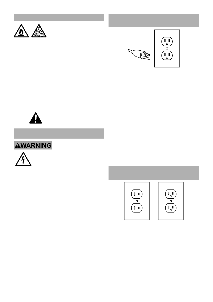
Grounded Tools: Tools with
Three Prong Plugs
3-Prong Plug and Outlet
1. Tools marked with “Grounding Required” have
a three wire cord and three prong grounding
plug. The plug must be connected to a properly
grounded outlet. If the tool should electrically
malfunction or break down, grounding provides
a low resistance path to carry electricity away
from the user, reducing the risk of electric
shock. (See 3-Prong Plug and Outlet.)
2. The grounding prong in the plug is connected
through the green wire inside the cord to the
grounding system in the tool. The green wire
in the cord must be the only wire connected
to the tool’s grounding system and must
never be attached to an electrically “live”
terminal. (See 3-Prong Plug and Outlet.)
3. The tool must be plugged into an appropriate outlet,
properly installed and grounded in accordance
with all codes and ordinances. The plug and outlet
should look like those in the preceding illustration.
(See 3-Prong Plug and Outlet.)
Double Insulated Tools: Tools
with Two Prong Plugs
Outlets for 2-Prong Plug
1. Tools marked “Double Insulated” do not
require grounding. They have a special
double insulation system which satisfies OSHA
requirements and complies with the applicable
standards of Underwriters Laboratories, Inc.,
the Canadian Standard Association,
and the National Electrical Code.
2. Double insulated tools may be used in either of the
120 volt outlets shown in the preceding illustration.
(See Outlets for 2-Prong Plug.)
Page 4 For technical questions, please call 1-888-866-5797. Item 57147
Page 5

Extension Cords
Note: Extension cords must not be
used with this item’s Charger.
1. Grounded tools require a three wire extension cord.
Double Insulated tools can use either
a two or three wire extension cord.
2. As the distance from the supply outlet increases,
you must use a heavier gauge extension cord.
Using extension cords with inadequately sized wire
causes a serious drop in voltage, resulting in loss of
power and possible tool damage. (See Table A.)
3. The smaller the gauge number of the wire, the
greater the capacity of the cord. For example,
a 14 gauge cord can carry a higher current
than a 16 gauge cord. (See Table A.)
4. When using more than one extension cord to make
up the total length, make sure each cord contains at
least the minimum wire size required. (See Table A.)
5. If you are using one extension cord for more
than one tool, add the nameplate amperes
and use the sum to determine the required
minimum cord size. (See Table A.)
6. If you are using an extension cord outdoors, make
sure it is marked with the suffix “W-A” (“W” in
Canada) to indicate it is acceptable for outdoor use.
7. Make sure the extension cord is properly wired
and in good electrical condition. Always replace
a damaged extension cord or have it repaired
by a qualified electrician before using it.
8. Protect the extension cords from sharp objects,
excessive heat, and damp or wet areas.
TABLE A: RECOMMENDED MINIMUM WIRE
GAUGE FOR EXTENSION CORDS* (120/240 VOLT)
NAMEPLATE
AMPERES
(at full load)
0 – 2.0 18 18 18 18 16
2.1 – 3.4 18 18 18 16 14
3.5 – 5.0 18 18 16 14 12
5.1 – 7.0 18 16 14 12 12
7.1 – 12.0 18 14 12 10 -
12.1 – 16.0 14 12 10 - -
16.1 – 20.0 12 10 - - -
* Based on limiting the line voltage drop to five volts at
150% of the rated amperes.
EXTENSION CORD
LENGTH
25´ 50´ 75´ 100´ 150´
Warning Symbols and Definitions
This is the safety alert symbol. It is used to
alert you to potential personal injury hazards.
Obey all safety messages that follow this symbol to
avoid possible injury or death.
Indicates a hazardous
avoided, will result in death or serious injury.
avoided, could result in death or serious injury.
avoided, could result in minor or moderate injury.
situation which, if not
Indicates a hazardous
situation which, if not
Indicates a hazardous
situation which, if not
Addresses practices not
related to personal injury.
Symbology
Double Insulated
V
~
A
Volts
Alternating Current
Direct Current
Amperes
WARNING marking concerning Risk
of Eye Injury. Wear ANSI-approved
safety goggles with side shields.
Read the manual before
set-up and/or use.
WARNING marking
concerning Risk of Fire.
Do not cover Charger
ventilation ducts.
Keep flammable objects away.
Charge on fireproof surface only.
WARNING marking concerning
Risk of Explosion.
Do not puncture, short, or open
battery packs and do not charge
damaged battery packs.
WARNING marking concerning
Risk of Electric Shock.
Properly connect power cord
to appropriate outlet.
Properly connect Charger’s power
cord to appropriate outlet.
Page 5For technical questions, please call 1-888-866-5797.Item 57147
Page 6
Specifications
Battery Rating
Electrical Rating 120VAC / 60Hz / .2A
Hercules 20 V Li-ion
(sold separately)
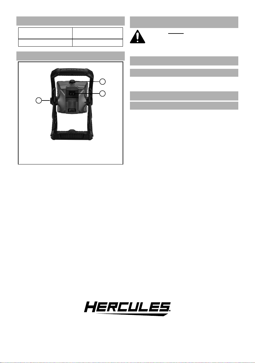
Functional Description
1
3
2
1. Power Button/Light Knob
2. Adjustment Knob
3. 120VAC Input Plug
OPERATION
Read the ENTIRE IMPORTANT
SAFETY INFORMATION section at the
beginning of this manual including
all text under subheadings therein
before set up or use of this product.
Tool Set Up
Battery Charging
Charge battery before using this tool. Follow instructions
included with battery charger (sold separately).
General Operation
Choose Power Supply
1. Battery Pack: Insert fully charged Battery
Pack into back of Work Light, making
sure it clicks into place securely.
2. 120VAC Extension Cord:
a. Remove Battery Pack from Work Light.
b. Connect the extension cord to the
120VAC Input on back of Work Light.
c. Plug the other end of the extension cord
into a grounded 120VAC outlet.
Page 6 For technical questions, please call 1-888-866-5797. Item 57147
Page 7
Work Light Placement
CAUTION! Keep Work Light and cord out of walkways.
1. Freestanding: Place Work Light on a flat surface.
3. Wall Mount:
WARNING! Verify that installation surface has no
hidden utility lines before drilling or driving screws.
WARNING! Do not install the
Work Light directly into drywall.
a. Select a suitable location for
hanging the Work Light.
b. Choose two adjacent studs. If drywall is
present, use a stud finder (sold separately)
and mark locations of studs.
c. Install a 2x4 across the studs.
d. Measure the distance between the
keyholes on the Work Light and mark
mounting locations on the 2x4.
e. Drill holes into the mounting locations,
then drive screws into holes, leaving
1/4″ of threads exposed.
f. Place large openings on keyholes over
screws. Pull down gently to lock screws
into upper parts of keyholes.
Note: For other types of walls, use appropriate
hardware.
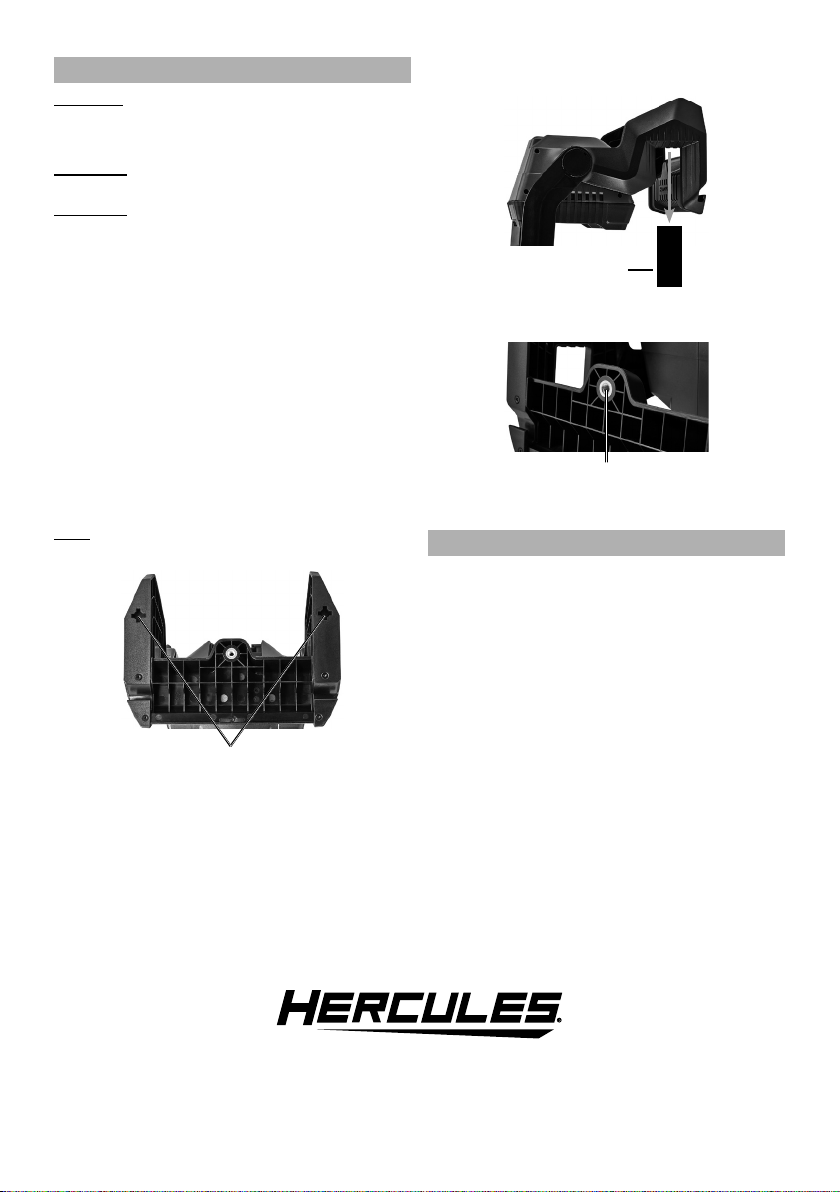
4. Rafter: Place Work Light over rafter, making
sure it is fully seated and secure.
Rafter
5. Tripod: Mount Work Light to a tripod (sold
separately) using Tripod Connector.
Tripod Connector
6. Loosen Adjustment Knob, rotate Work Light to
desired position, then tighten Adjustment Knob.
Operation
1. Press Power Button to turn on Work Light.
Rotate Light Knob to adjust brightness of the
light. Press Power Button again to turn off.
2. After use, remove Work Light from wood studs, rafter,
or Tripod. Unplug or remove Battery Pack. Clean,
then store the tool indoors out of children’s reach.
Keyholes
Page 7For technical questions, please call 1-888-866-5797.Item 57147
Page 8

MAINTENANCE AND SERVICING
Cleaning, Maintenance,
and Lubrication
Procedures not specifically explained
in this manual must be performed
only by a qualified technician.
TO PREVENT SERIOUS INJURY FROM
ACCIDENTAL OPERATION:
Make sure that the Power Button is in the off
position and unplug the tool from its electrical
outlet or remove its Battery Pack before
performing any procedure in this section.
1. BEFORE EACH USE, inspect the general
condition of the tool. Check for:
• leaking, swollen, or cracked battery pack,
• loose hardware,
• misalignment or binding of moving parts,
• damaged cord/electrical wiring,
• cracked or broken parts, and
• any other condition that may
affect its safe operation.
2. AFTER USE, wipe external surfaces
of the tool with clean cloth.
3. Li-Ion BATTERY MUST BE RECYCLED OR
DISPOSED OF PROPERLY.
Do not short, incinerate or open battery.
4. Disconnect battery pack and store battery pack,
charger, and tool in dry, indoor area out of
reach of children and away from metal objects
(i.e., paperclips, coins) to prevent shorting.
Troubleshooting
Problem Possible Causes Likely Solutions
Work Light will
not turn on.
Follow all safety precautions whenever diagnosing or servicing
the tool. Disconnect power supply before service.
1. Cord not connected.
2. No power at outlet.
3. Battery Pack not properly connected.
4. Battery Pack not properly charged.
5. Battery Pack burnt-out.
1. Check that cord is plugged in.
2. Check power at outlet. If outlet is unpowered,
turn off tool and check circuit breaker.
If breaker is tripped, make sure circuit is right
capacity for tool and circuit has no other loads.
3. Remove Battery Pack, make sure there
are no obstructions, reinsert the Battery
Pack according to its shape (it should
only fit one way), and press firmly until
the Battery Pack locks in place.
4. Make sure Charger is connected and
operating properly. Give enough time
for Battery Pack to recharge properly.
5. Dispose of old Battery Pack
properly or recycle. Replace Battery Pack.
Page 8 For technical questions, please call 1-888-866-5797. Item 57147
Page 9

PLEASE READ THE FOLLOWING CAREFULLY
THE MANUFACTURER AND/OR DISTRIBUTOR HAS PROVIDED THE PARTS LIST AND ASSEMBLY DIAGRAM
IN THIS MANUAL AS A REFERENCE TOOL ONLY. NEITHER THE MANUFACTURER OR DISTRIBUTOR
MAKES ANY REPRESENTATION OR WARRANTY OF ANY KIND TO THE BUYER THAT HE OR SHE IS
QUALIFIED TO MAKE ANY REPAIRS TO THE PRODUCT, OR THAT HE OR SHE IS QUALIFIED TO REPLACE
ANY PARTS OF THE PRODUCT. IN FACT, THE MANUFACTURER AND/OR DISTRIBUTOR EXPRESSLY
STATES THAT ALL REPAIRS AND PARTS REPLACEMENTS SHOULD BE UNDERTAKEN BY CERTIFIED AND
LICENSED TECHNICIANS, AND NOT BY THE BUYER. THE BUYER ASSUMES ALL RISK AND LIABILITY
ARISING OUT OF HIS OR HER REPAIRS TO THE ORIGINAL PRODUCT OR REPLACEMENT PARTS
THERETO, OR ARISING OUT OF HIS OR HER INSTALLATION OF REPLACEMENT PARTS THERETO.
Record Product’s Serial Number Here:
Note: If product has no serial number, record month and year of purchase instead.
Note: Some parts are listed and shown for illustration purposes only, and are not available
individually as replacement parts. Specify UPC 792363571470 when ordering parts.
Page 9For technical questions, please call 1-888-866-5797.Item 57147
Page 10

PARTS LIST AND DIAGRAM
Part Description Qty
1 Front Housing 1
2 Lens 1
3 Reflector 1
4 Nut 8
5 Screw 8
6 Screw 2
7 High Power COB LED 1
8 Heatsink 1
9 Ul AC/DC Adapter 1
10 PCBA 1
11 Tripod Connector 1
12 Base 2
13 Contact Plate Holder 1
14 Right Housing 1
15 O-Ring 2
16 Right Leg 1
Part Description Qty
17 Screw 4
18 Bolt M5 1
19 Adjustment Knob 1
20 Rotate Shaft (R) 1
22 O-Ring 2
23 Front Handle 1
24 Plate 1
25 Back Handle 1
26 Screw 12
27 Power Button/Light Knob 1
28 Left Housing 1
29 Left Leg 1
30 Rotate Shaft (L) 1
31 Screw 1
32 Left Cover 1
Page 10 For technical questions, please call 1-888-866-5797. Item 57147
Page 11

LIMITED 90 DAY WARRANTY
Harbor Freight Tools Co. makes every effort to assure that its products meet high quality and durability standards,
and warrants to the original purchaser that this product is free from defects in materials and workmanship for the
period of 90 days from the date of purchase. This warranty does not apply to damage due directly or indirectly,
to misuse, abuse, negligence or accidents, repairs or alterations outside our facilities, criminal activity, improper
installation, normal wear and tear, or to lack of maintenance. We shall in no event be liable for death, injuries
to persons or property, or for incidental, contingent, special or consequential damages arising from the use of
our product. Some states do not allow the exclusion or limitation of incidental or consequential damages, so the
above limitation of exclusion may not apply to you. THIS WARRANTY IS EXPRESSLY IN LIEU OF ALL OTHER
WARRANTIES, EXPRESS OR IMPLIED, INCLUDING THE WARRANTIES OF MERCHANTABILITY AND FITNESS.
To take advantage of this warranty, the product or part must be returned to us with transportation charges
prepaid. Proof of purchase date and an explanation of the complaint must accompany the merchandise.
If our inspection verifies the defect, we will either repair or replace the product at our election or we may
elect to refund the purchase price if we cannot readily and quickly provide you with a replacement. We will
return repaired products at our expense, but if we determine there is no defect, or that the defect resulted
from causes not within the scope of our warranty, then you must bear the cost of returning the product.
This warranty gives you specific legal rights and you may also have other rights which vary from state to state.
Page 11For technical questions, please call 1-888-866-5797.Item 57147
Page 12

Email our technical support at: productsupport@harborfreight.com
Visit our website at: http://www.harborfreight.com
For technical questions, please call 1-888-866-5797
Copyright© 2020 by Harbor Freight Tools®. All rights reserved. No portion of this manual or
any artwork contained herein may be reproduced in any shape or form without the express
written consent of Harbor Freight Tools. Diagrams within this manual may not be drawn
proportionally. Due to continuing improvements, actual product may differ slightly from the
product described herein. Tools required for assembly and service may not be included.
26541 Agoura Road • Calabasas, CA 91302 • 1-888-866-5797
 Loading...