

Page 1
ZEKOO
www.zekoohardware.com
Barn Door Hardware
Installation Manual
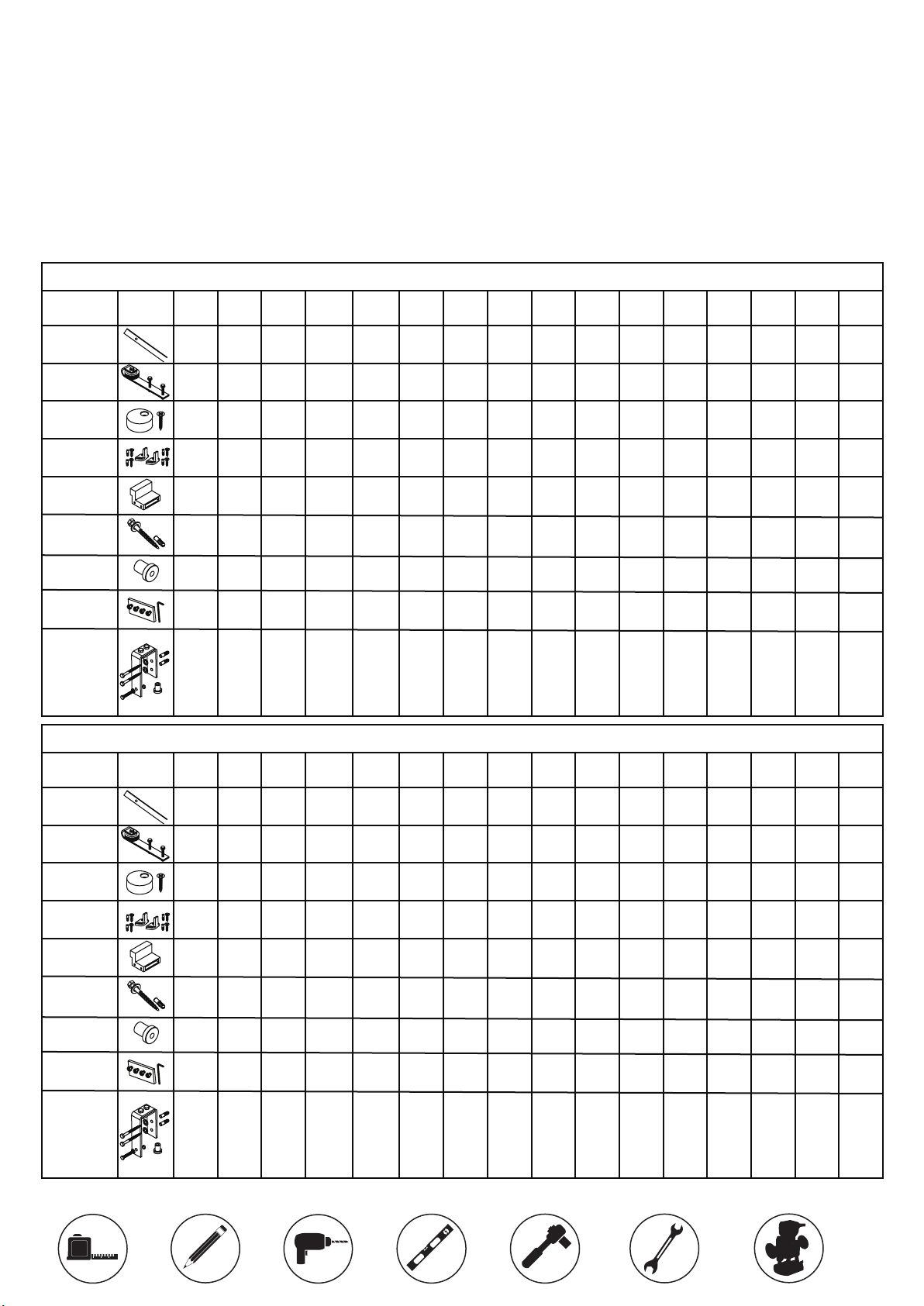
※Check the Quantities
Note: If you encounter any problem with the package and the following installation,
please email us at [email protected]. Please also tell us your “ORDER ID,”
we will solve any issues for you as soon as possible.
2 Doors Bypass Hardware Kit Includes
Part
Name
Flat
Track
Steel
Hanger
Anti-jump
Pad
Floor
guide
Door
Stopper
Lag
Screws
picture
5FT4FT 6FT 6.6FT 7.5FT 8FT 9FT 11FT10FT 12FT 13FT 14FT 15FT 16FT 17FT 18FT
6
6
4
2
2
2
2
4
4
4
4
4 4 4 4 4 4 4 4 4 4 4 4 4 4 4 4
2
2
2
2
4 4 4 4 4 4 4 4 4 4 4 4 4 4 4 4
5
5
4
3
2
4
4
4
4
4
4
2
2
2
2
2
2
10
10
8
8
6
6
6
4
4
4
4
4
4
4
4
4
4
4
4
2
2
2
2
2
15
14
13
12
10
6
4
2
Spacer
Junction
Plate
Bypass
Bracket
Suit
Part
Name
Flat
Track
Steel
Hanger
Anti-jump
Pad
Floor
guide
Door
Stopper
Lag
Screws
2in
picture
5
5
4
3
0
0
0
0
3 4 5 5 6 6 6 8 8 1010 10 12 13 14 15
6
4
4
2
2
2
2
2
2
0
2
2
15
14
13
12
10
10
10
8
8
6
6
4 Doors Bypass Hardware Kit Includes
5FT4FT 6FT 6.6FT 7.5FT 8FT 9FT 11FT10FT 12FT 13FT 14FT 15FT 16FT 17FT 18FT
6
6
4
4
4
4
4
4
4
4
2
2
2
2
8
8
8
8
8 8 8 8 8 8 8 8 8 8 8 8 8 8 8 8
4 4 4 4 4 4 4 4 4 4 4 4 4 4 4 4
8 8 8 8 8 8 8 8 8 8 8 8 8 8 8 8
5
5
4
3
2
8
8
8
8
8
8
8
8
8
8
8
15
14
13
12
10
10
10
8
8
6
6
6
4
6
8
Spacer
Junction
Plate
3
0
5
4
0
0
Bypass
Bracket
Suit
3 4 5 5 6 6 6 8 8 1010 10 12 13 14 15
2in
● Installation Tools
Pencil Level RatchetWrenchRuler
15
14
13
12
10
10
10
8
8
6
6
Drill
6
4
4
4
2
2
2
2
2
2
2
2
0
Router
5
0
1
Page 2
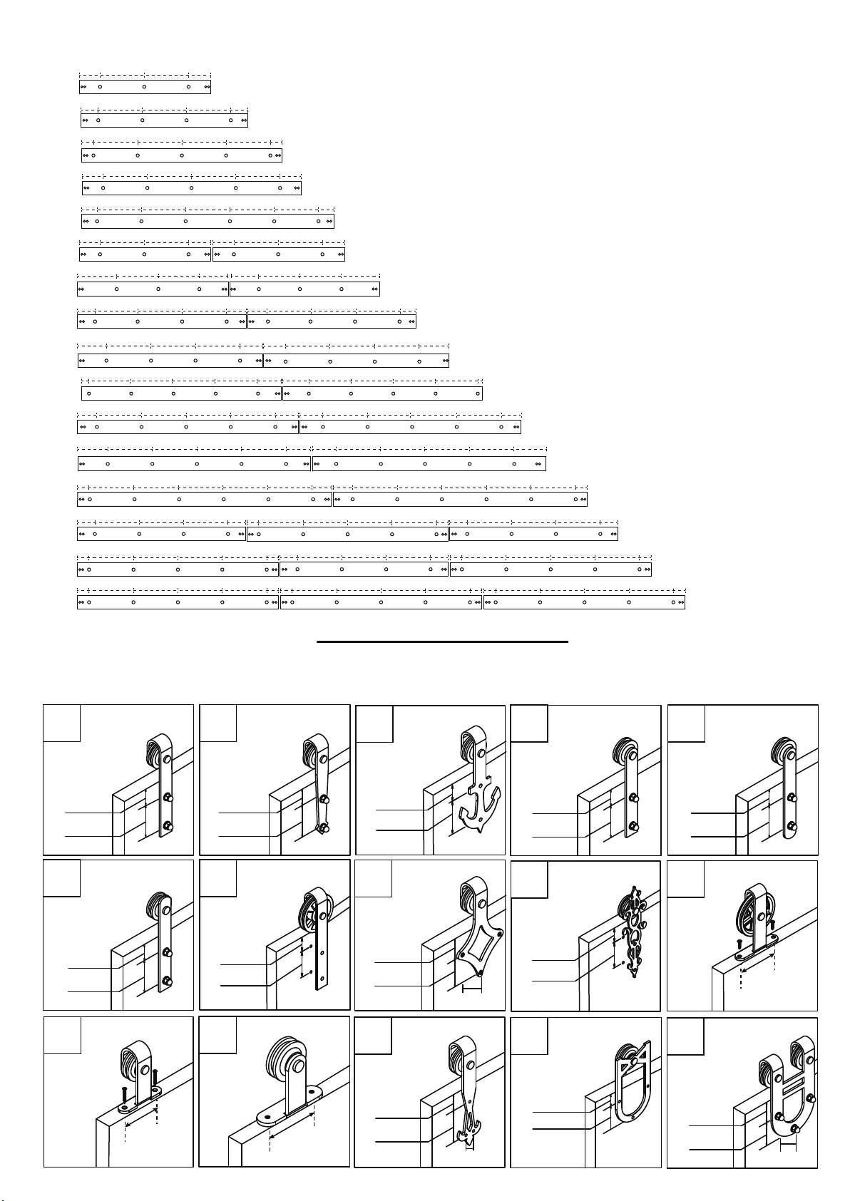
※Chart: Track Junction
16” 16” 8”8”
4FT
16” 16” 16” 6”6”
5FT
16” 16” 16” 16” 4”4”
6FT
16” 16” 16” 16” 7.6”7.6”
6.6FT
16” 16” 16” 16” 16” 5”5”
7.5FT
16” 16” 8”8” 16” 16” 8”8”
8FT
9FT
10FT
11FT
12FT
13FT
14FT
15FT
16FT
17FT
18FT
16” 16” 8”14”
16” 16” 16” 8”4” 16” 16” 16” 4”8”
16” 16” 16”10” 8”
16”0.98” 0.98”16” 16” 16”
16” 16” 16” 16” 8”6” 16” 16” 16” 16” 6”8”
16” 16” 16” 16”
16” 16” 16” 16” 16” 8”2” 16” 16” 16” 16” 16” 2”8”
16” 16” 16” 6”6” 16” 16” 16” 6”6”
16” 16” 16” 16” 4”4”
16” 16” 16” 16” 4”4”
8” 16”
8” 16” 16” 16” 10”
8”
16”
16” 16” 16” 16”8”
8”12”
8”
16” 16” 16” 16” 4”4”
16” 16” 16” 6”6”
16” 16” 16” 16” 4”4” 16” 16” 16” 16” 4”4”
14”
16”
16”
16” 16” 12”
16” 16” 16” 16” 4”4”
Prepare Your Doors
● Steel Hanger Installation Dimensions
Note: Find the installation dimensions for your Steel Hanger style in the chart below:
NO.1
1-5/16”
3-9/16”
NO.6
2-1/16”
3-9/16”
NO.11
NO.2
1-5/16”
3-9/16”
NO.7
1-9/16”
3-9/16”
NO.12
NO.3
1-5/16”
4-1/8”
NO.8
2-7/16”
NO.13
3”
NO.4
1-5/16”
3-9/16”
NO.9
1-5/16”
3-9/16”
2-3/8”
NO.14 NO.15
NO.5
2-1/16”
3-9/16”
NO.10
4-3/4”
3-15/16”
3-15/16”
1-1/8”
3-9/16”
15/16”
1-1/4”
2-15/16”
11/16”
3-5/16”
2-3/8”
2
Page 3
※Hardware Installation
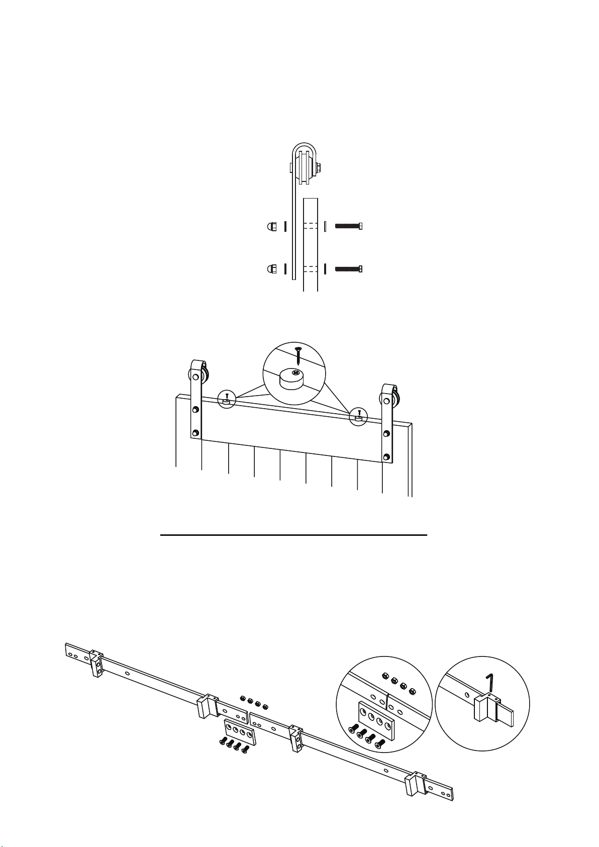
Step 1: Attach Steel Hangers to Your Doors
a.Please choose the correct roller installation according to your roller shape on page
2 above and the illustration below.
b.Drill 7/16”holes at the distances from the top of the doors shown in the above
chart.Note: The Hanger Bolts are inserted through the back of the door (i.e. the Hanger
and Acorn Nuts attach to the front face of the door).(except:No.10~No.14)
.Attach Hangers with the Hanger Bolts, Washers and Acorn Nuts as shown below.
c
Step 2: Install anti-jump pad
As shown in the illustration, the screw is near the front edge of your door (recommended: drill pilot hole to avoid splitting). Do not over tighten.
Prepare and Install the Tracks
Step 3: Connect Tracks And Install Door Stoppers
a.Connect your tracks with junction plates if needed.
b.Loosely install the Door Stoppers near each end of the track (final positioning will
be determined at the end of the installation (Step 10)).
3
Page 4
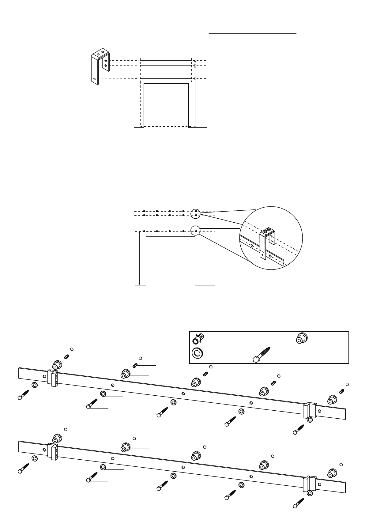
Step 4: Draw 3 Lines for the Track and Brackets
a.Using a level, draw line ① for the Track, at the door height + 1-11/16” above the floor.
b.Pencil lines ② and ③ for the Bracket above line ① as shown in the illustrations below.
③
②
①
Step 5: Mark and Drill Track Holes
a.Line up a Track on lowest line and mark the location of the holes. Note: holes are
16” apart, line up with wall studs if possible.
b.Use level to mark the hole locations directly above the original marks on the upper
two lines. (Tip: Take care to make the upper two marks parallel to each other so Hangers
hang straight.)
c.Concrete wall: Drill holes by using a 3/8” concrete drill bit.
d.Wood framed wall: Drill out the holes by using a drill with 1/4”drill bit.
1-3/8”
2-9/16”
Door Height+1-11/16”
Door Height+1-11/16”
Step 6: Install The Inside Track
Using the Spacers, Long Lag Screws, and Washers (and hollow wall anchor if necessary), attach the Track to the wall as shown in the illustration below.
Tip: Loosely attach one end of the Track with the other end resting on the ground.
Then swing track up and attach other end. Finally, fill in the middle holes.
Concrete wall
①hollow wall anchor
③Washers
④4” Lag Screws
②Spacer
①
②
③
④
Wooden wall
④
②
③
4
Page 5
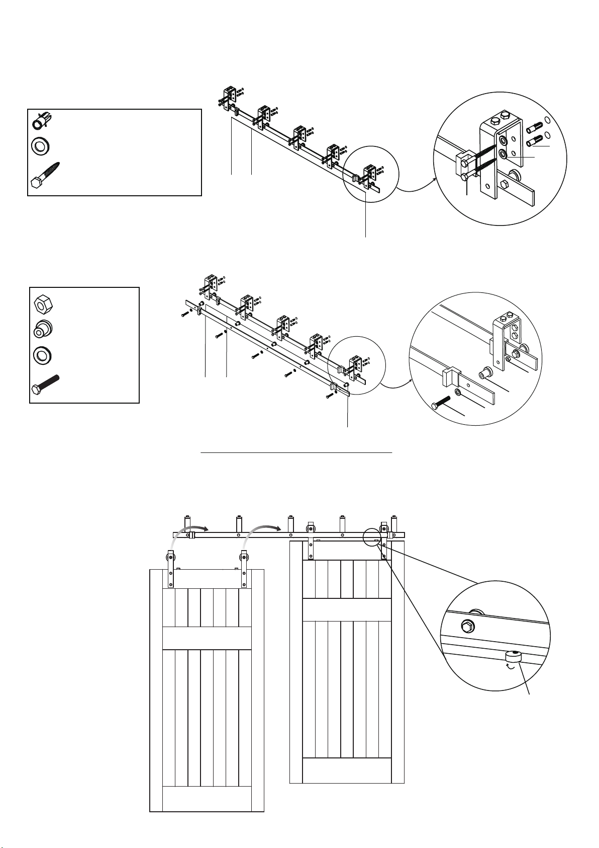
Step 7: Attach Brackets to the Wall
a.Loosely attach each bracket to the wall with Short Lag Screws and washers (and
hollow wall anchors if needed).
b.Fully tighten all Lag Screws with your ratchet. Don’t overtighten screws as you may
strip the studs or anchors.
①hollow wall anchor
②Washers
②
③2-9/16” Lag Screws
③
Step 8: Install the Outside Track
Using the spacers, Track Bolts, Washers and Nuts attach the outside Track to the
Bypass Bracket as shown in the illustrations below.
①Nuts
②Spacer
③Washers
④track bolt
①
②
③
④
①
Hanging and Positioning Doors
Step 9: Install Your Doors
Lift and hang your doors on the Track, and then twist the Anti-Jump Pad toward the
wall so that it is under the Track.
twist the Anti-Jump
Pad toward to the wall
5
Page 6
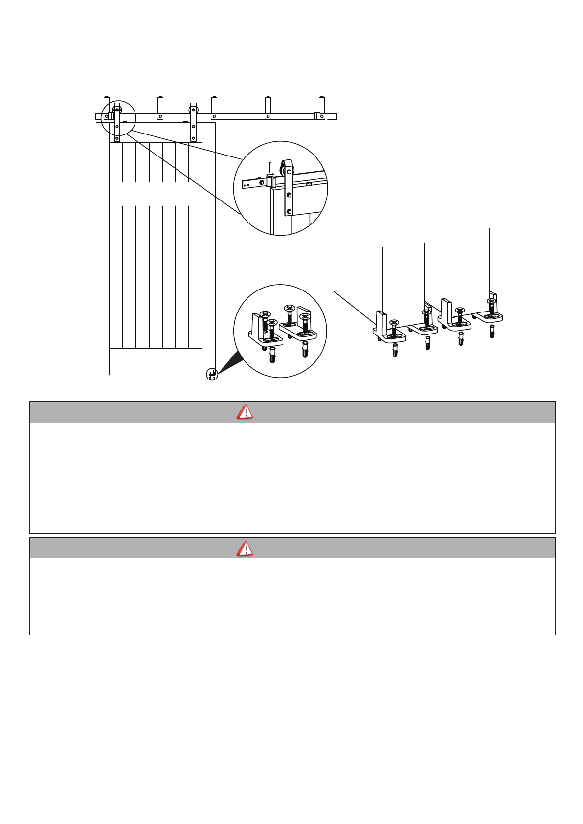
Step 10: Install the Floor Guide
a.Position the door at your desired open position, put half of the floor guide under the
door, mark the location, and then fix guide to the floor.
b.Position doors in your desired open and closed position and adjust Door Stoppers.
Inside Door
Outside Door
WARNING
• Failure to wear proper safety gear (i.e.,eye protection) may result in serious injury or death. Always wear proper safety gear before
using power tools.
• Improper operation of power tools may result in loss of control, serious injury or death. Always ensure you have complete control of
the power tool and the work area is free of hazards before operatiog a power tool.
• Lack of secure clamping of the door may result in unexpected movement of the door,loss of power tool control and serious injury or
death. Always securely clamp the door in place before cutting,or drilling, the door.
• Lack of ,or improperly installed Anti-jump Disc may result in the door coming off the track and cause serious injury or death.
installation of Anti-jump Disks are required for safe operation of this hardware. installed properly, these discs will keep the door
securely attached to the teack.
CAUTION
• Mishandling of heavy objects (i.e.,doors) may cause a loss of balance and serious injury. Always be sure you have a secure hold
on the object and are balanced before moving the object.Always wear safety shoes when lifting heavy objects.
• Getting body parts (i.e., hair,fingers) caught in moving parts may cause pinching and serious injury.Do not put fingers in parts that
may move and always remove or contain anything on your body that may become entangled with a moving part.
• Closing sliding doors with your hand on the end of the door may result in your hand, or fingers, getting caught between the door
and other solid objects (i.e., another door, molding) causing serious injury. Always use the door handle to close doors.
Usage Statement:
Use of excessive force when opening, and closing,the door(s) may result in damage to the hardware. Always hold the handle and gently
open and close the door(s).
Warranty Statement:
5 year straight unconditional warranty service enables every single hardware’s durability coverage during its life time.
www.zekoohardware.com
6
 Loading...