

1 4 2 5 6
3
1.
2.
1.
2.
S2,5
4xM4 Countersunk Bolts
4xØ8 mm Plastic Dowels
4x4,8x50 mm
Flat Head Screws
A
B
C
D
E
F
4 11/
64
2 3/
32
A
4.
3.
B C D E F
4xM4 Countersunk Bolts
S2,5
4xM4 Security Torx
Countersunk Bolts
2.
1.
1.
2.
3.
4xM5 Washers
0°
S2,5
2xM4 Countersunk Bolts
TX20
HEPER USA LLC
W227 N546 Westmound
Drive Waukesha
WI 53186 – USA
Tel: +1 917 244 20 32
infoUS@hepergroup.com
www.heperlighting.com
Inch
Inch
Inch
3
/
4
Inch
3
/
8
Inch
63
Inch
/
64
5
/
16
1,8 lb ft
DOGO EX
Installation&Maintenance Instructions
4,4 lb ft
1.8 lb ft
2020-0/09.10.2020
1.8 lb ft
1.8 lb ft
7
8
1.
2.
3.
1.
2.
0,7 lb ft
2xM3 Flat Head Screws
2xM3 Flat Head Screws
0,7 lb ft
English
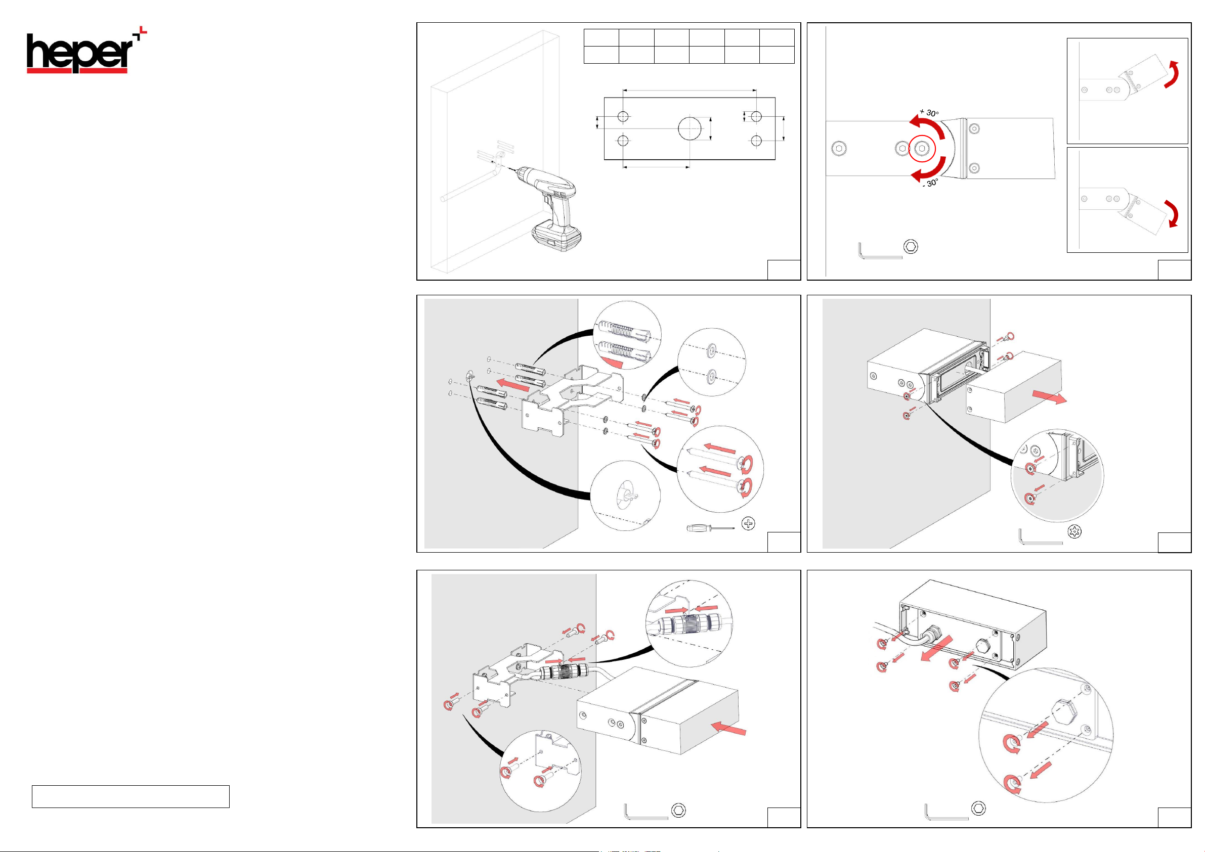
ASSEMBLY INSTRUCTIONS
To make the wall mounting of the product;
1. . Holes and cable hole are drilled to allow the product to be mounted on the wall
2. . Assembling the wall connection apparatus
2.1. Make sure that the line power cable is up to the product.
2.2. Plastic dowels are driven into the holes (4 pieces, Ø8 Plastic Dowels)
3. Note: The dowels should not be damaged during this process.
2.3. The wall bracket is leaning against the wall by aligning the holes.
2.4. The wall connection apparatus is screwed to the wall with a torque of 4.8 lb ft (4
pieces, 4,8x50 Pointed Star Cylindrical Head Bolt)
4. . Mounting the product to the wall connection apparatu
3.1. The cable coming from the wall and the cable coming out of the product are assembled
with the help of a socket.
Note: The socket for connecting the cables is not supplied with the product. Please supply
socket with minimum IP66 certification suitable for the product.
3.2. The product is placed on the wall connection apparatus.
3.3.The countersunk Imbus bolts that connect the product to the body are tightened to their
places with 1.8 lb ft torque (4 pieces, M4 Countersunk Imbus Bolts).
5. The product can rotate up and down with an angle of 30 °. In order to angle the lighting
fixture, 2 countersunk Imbus bolts marked in the visual are loosened mutually, after the
luminaire is brought to the desired angle, the countersunk head Imbus bolts are mutually
tightened with 1.8 lb ft torque (2 pieces, M4 Countersunk Imbus Bolts).
To replace the LED driver;
Note: Before starting this process, the electrical connection to the product must be
disconnected.
5. . To disassemble the produc
5.1. The safety torx bolts with countersunk head that connect the product to the body It is
removed (4 pieces, M4 Countersunk Head Safety Torx Bolts).Note: After the LED driver
replacement is completed, the product is placed in its place and the countersunk head safety
torx bolts are tightened with 1.8 lb ft torque (4 pieces, M4 Torx Bolts with Countersunk Head
Safety).
5.2. The product is displaced.
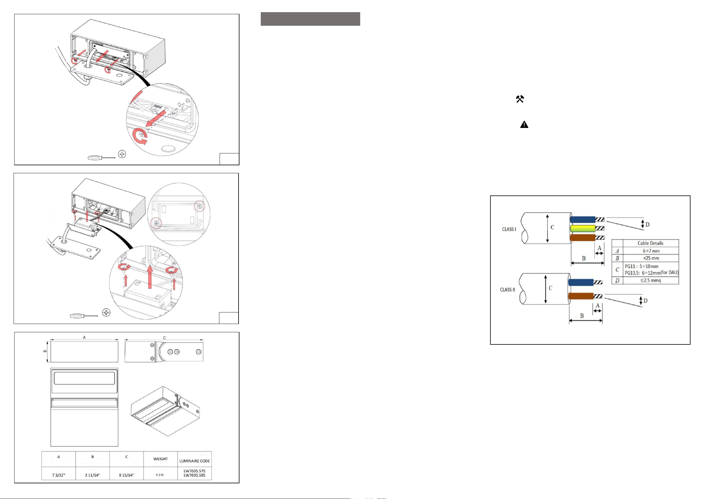
6. . To remove the back cover of the product
6.1. The countersunk Imbus bolts holding the rear cover are removed from their places (4
pieces, M4 Countersunk Bolt).
6.2. The back cover is removed.
Note 1: While removing the cover, care should be taken not to damage the electrical
connections inside the product. This should be done sensitively.
Note 2: After the LED driver replacement is completed, the rear cover is placed in its place and
the countersunk head bolts are tightened with 1.8 lb ft torque (4 pieces, M4 Countersunk Imbus
Bolts).
7. . Removing the cartridge group
7.1. The star cylindrical head bolts holding the cartridge sheet are removed.
7.2. The cartridge group is removed.
Note 1: While removing the cartridge group, care should be taken not to damage the electrical
connections inside the product. This should be done sensitively.
Note 2: After the LED driver replacement is completed, the cartridge group is placed in its
place and the star cylindrical head bolts are tightened with a torque of 0.7 lb ft (2 pieces of
M3 Star Cylindrical Head Bolt).
8. . To remove the LED drive
8.1. The star cylindrical head bolts holding the LED drive are removed and the cables
connected to the LED driver are disconnected.
8.2. The LED driver is removed.
Note 1: While removing the cables on the LED driver, care should be taken not to damage the
cables and the product. This should be done sensitively.
Note 2: The new LED driver is placed in its place and the star cylindrical head bolts
are tightened with a torque of 0.7 lb ft (2 pieces, M3 Star Cylindrical Head Bolt).
Note 3: Cables are mounted to the new LED driver.
Note 4: The procedures for changing the LED driver are reversed and the product is turned off.
WARNINGS AND REMARKS FOR INSTALLATION AND
MAINTENANCE
• The light source contained in this
service agent or a similar qualified person. Always switch off the power prior to installation,
maintenance or repair activities.
• The manufacturer is then discharged from liability when damage is caused by improper use or
installation.
• If any luminaire is subsequently modified, the persons responsible for the modification shall be
considered as manufacturer.
• To reduce the risk of death, personal injury or property damage from fire, electric shock, falling
parts, cuts, abrasions and other hazards, please read all warnings and instructions included with
the luminaire, on the luminaire’s packaging and affixed to the luminaire itself..
• Installatio n
• LEDs are high-quality electronic components! Please avoid contacting the light output opening of
the LED directly during installation or relamping.
IMPORTANT
• To ensure secure connection, the luminaire housing must be positioned precisely in relation to
the mounting plate.
Cleaning And Maintenance
• Clean luminaire regularly with solvent-free cleaners from dirt. Please do not clean the luminaire
with using high-pressure liquids.
Replacing the LED module
The designation of the LED module is noted on a label in the luminaire.
The light colour and light output of HEPER replacement modules correspond to those of the
modules originally fitted. The module can be replaced by qualified persons using
luminaire shall only be replaced by the manufacturer or his
 Loading...