

HEP LMV10W12 UNI, LLV20W12 UNI, LMV10W24 UNI, LLV20W24 UNI User guide [ml]
Beschreibung und Einbauanweisung
LED Driver mit konstanter Ausgangsspannung zum Betreiben von LED
(Elektronisches Schaltnetzteil)
TYP: LMV10W12 UNI, LLV20W12 UNI, LMV10W24 UNI, LLV20W24 UNI Schutzklasse 2 CE
1.Technische Daten:
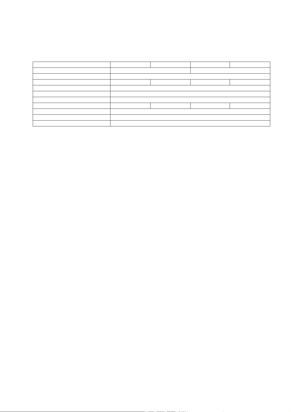
Best.-Nr.: LMV10W12 UNI LLV20W12 UNI LMV10W24 UNI LLV20W24 UNI
Konstante Ausgangsspannung 12VDC SELV equivalent 24VDC SELV equivalent
Nennspannung 100-240V~ 50-60Hz
Teillastbereich 0-10W 0-20W 0-10W 0-20W
Leerlaufsicherheit gewährleistet
Kurzschluss- und Überlastschutz Elektronische Abschaltung mit automatischem Wiederanlauf
Umgebungstemperatur ta -20°C - +50°C
Gehäusetemperatur tc-Punkt Max.70°C Max.75°C Max.70°C Max.75°C
EMV Konformität EN 61547, EN 55015, EN 61000-3-2, EN 61000-3-3
Primärleitung Min. H03VV-F 2x0,75mm² für Zugentlastung
Sekundärleitung Min. H03VV-F 2x 0,75mm², für Zugentlastung
2. Einbauhinweise
Die Installation darf nur in Übereinstimmung mit internationalen und nationalen Normen
durch eine Elektrofachkraft ausgeführt werden.
Die LED Driver sind nur zur Verwendung mit LED bestimmt die eine Konstantspannung
von VDC gemäß den Werten in der Tabelle benötigen.
Beim Anschließen der LED ist darauf zu achten, dass + und – auf die richtigen Klemmen
beim LED Driver aufgelegt werden.
Der Schutz gegen elektrischen Schlag ist bei Arbeiten an elektrischen Anlagen durch Freischalten
der Anlage sicherzustellen. Primär- und Sekundärleitungen kreuzungsfrei verlegen (Funkschutz).
Bei außerhalb von Leuchten montierten LED Driver ist auf eine korrekte Befestigung der Primär- und
Sekundärleitungen in den Zugentlastungen zu achten und er ist über seine Anschraublöcher auf den
jeweiligen Untergrund fest zu verschrauben.
Die Tc Temperatur darf in keiner Einbauweise überschritten werden.
Die Geräte enthalten keine servicefähigen Bauteile und dürfen daher nicht geöffnet werden.
3. Wichtige Hinweise
Unsere LED Driver sind surgespannungsfest bis weit über die von der einschlägigen Norm
vorgeschriebenen Werte. Zum Schutz vor höheren Überspannungen, die z.B. beim Schalten von
Leuchtstofflampen und Entladungslampen mit induktivem Vorschaltgerät, Motoren (Ventilatoren, usw.)
und anderen induktiven Lasten auftreten, sind die Lastkreise für diese Gerätegruppen
deutlich voneinander zu trennen.
!!Der LED Driver ist nicht über einen Phasenan- oder -abschnittdimmer regelbar!!
4. Sicherheitsfunktion
Der LED-Driver schaltet bei Kurzschluss oder Überlast automatisch ab. Er besitzt keine Sicherung
herkömmlicher Art. Der Laststromkreis wird folglich nicht aufgetrennt!
Nach Beheben des Fehlers schaltet der LED Driver automatisch wieder ein.
5. Wärmeableitung bzw. Wärmeübergang
Ein Betrieb in überhöhter Umgebungstemperatur oder durch Fremderwärmung verkürzt die Lebensdauer.
Beim Einbau ( vor allem in Leuchten ), ist durch geeignete Maßnahmen für eine Wärmeabfuhr
( Wärmeübergang ) zu sorgen. Die Umgebungstemperatur und/oder
Tc-Punkt Temperatur darf zu keinem Zeitpunkt überschritten werden. Für Schäden, die aus entsprechend
unsachgemäßem Gebrauch entstehen, wird keine Haftung übernommen.
Description and Mounting Instructions
LED Driver with constant output voltage for the operation of LED
(Electronic switch-type power supply unit)
TYPE: LMV10W12 UNI, LLV20W12 UNI, LMV10W24 UNI, LLV20W24 UNI Protection class 2 CE
1 Technical Data:
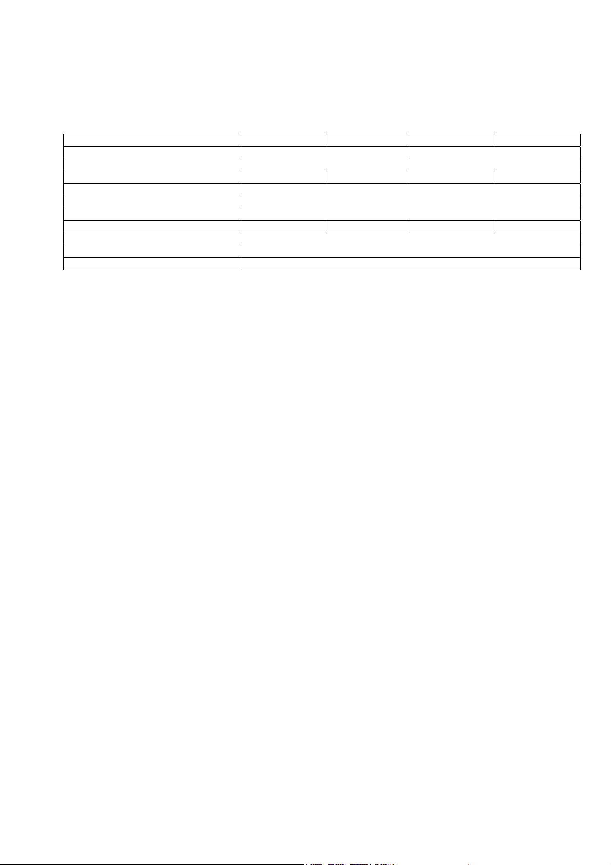
Art. No.: LMV10W12 UNI LLV20W12 UNI LMV10W24 UNI LLV20W24 UNI
Constant output voltage 12VDC SELV equivalent 24VDC SELV equivalent
Rated voltage 100-240V~ 50-60Hz
Shared load operation 0-10W 0-20W 0-10W 0-20W
Open-circuit safety guaranteed
Short circuit and overload protection Electronic disconnection with automatic restart
Ambient temperature ta -20°C - +50°C
Housing temperature tc-point Max.70°C Max.75°C Max.70°C Max.75°C
EMC conformity EN 61547, EN 55015, EN 61000-3-2, EN 61000-3-3
Primary cable Min. H03VV-F 2x0,75mm² for strain relief
Secondary cable Min. H03VV-F 2x0,75mm² for strain relief
2. Installation Instructions
The installation may only be carried out by an electrical specialist in accordance with international and
national standards.
The LED Driver is strictly suited for the use with LED that require a constant voltage of VDC
according to the values in the table.
When connecting the LED, careful attention should be paid to connecting + and – to the right
terminals on the LED Driver.
When working on electrical systems, the protection against electric shock is to be ensured by disconnecting
the system.
Instal primary and secondary mains intersection-free (RFI protection)
LED Drivers mounted outside of luminaires are to be screwed tightly to the respective surface by their screw
holes and careful attention is to be paid to the primary and secondary cables being fastened securely in the
strain relief.
The tc temperature may not be exceeded for any kind of mounting. The devices do not contain any
serviceable components and may not be opened.
3. Important Information
Our LED Drivers are surge-voltage-stable with values above those prescribed by the respective standards.
As a protection against high voltage surges, as they occur e.g. when switching fluorescent lamps and
discharge lamps with an inductive ballast, motors (fans, etc.) and other inductive charges, the load circuits
for devices of this kind are to be clearly separated from each other.
!!The LED Driver cannot be regulated via a phase cut-on or cut-off dimmer!!
4. Safety Functions
In case of a short circuit or overload the LED Driver will automatically cut off. It does not have a fuse of the
conventional kind. Thus the load circuit is not separated!
As soon as the defect has been repaired, the LED Driver will automatically cut back in.
5. Heat Dissipation and Heat Transfer
Operation in excess ambient temperature or through external heating will reduce the service life. During the
installation process ( particularly into luminaires ), heat dissipation ( heat transfer ) is to be provided through
suitable measures. The ambient temperature and/or tc temperature may not be exceeded at any time. We
are not liable for damage resulting from improper use.
 Loading...