

Page 1
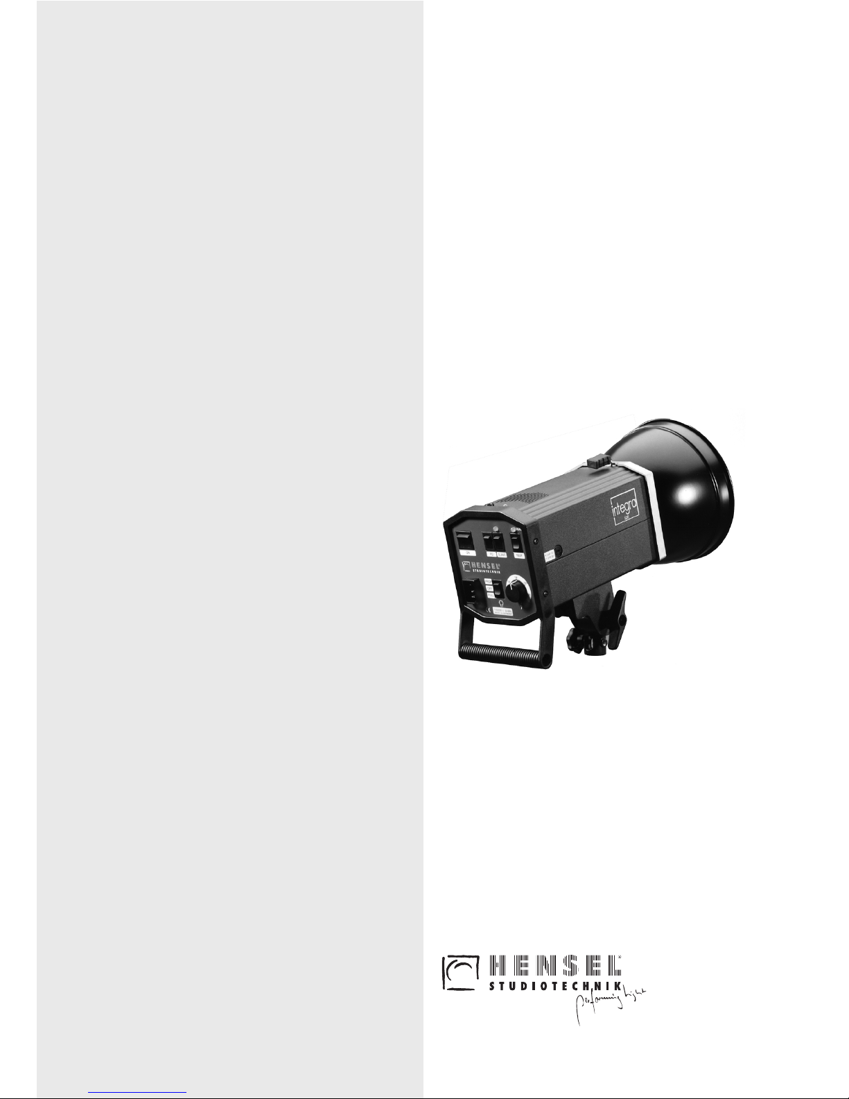
manual
User
COMPACTINTEGRA
250
500
INTEGRA
250
500
Page 2
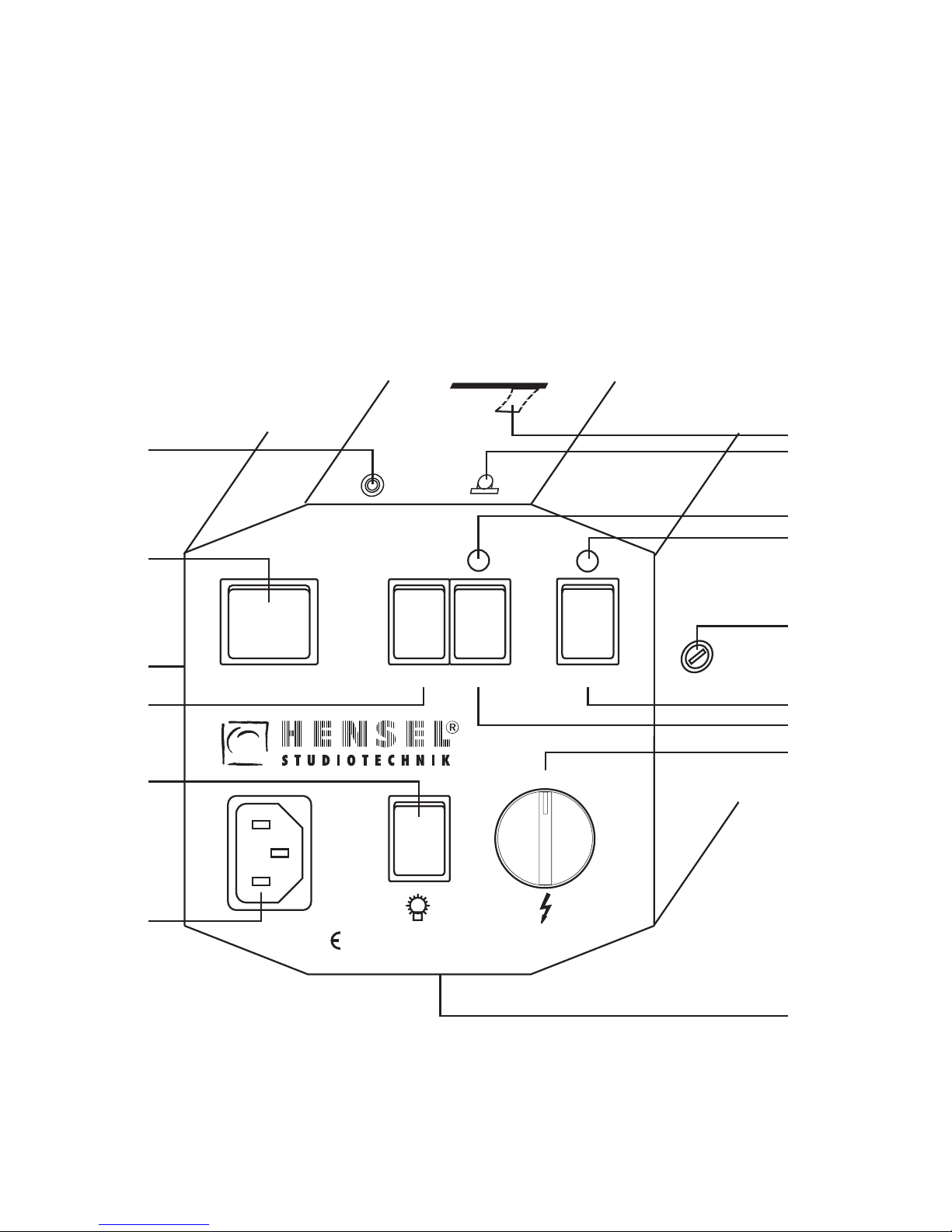
INTEGRA Compact 250 / 500INTEGRA Compact 250 / 500
1/16
1/8
1/4
1/2
1/1
TEST
READY
230V / 50-60Hz
MADE IN GERMANY
PROP
OFF
FULL
ON FC
SLAVE
AF
1
12
11
2
8
7
15
6
5
9
3
4
14
13
10
Control panel (back view)Control panel (back view)
right
top
top
bottom
left
Page 3

HENSEL Studiotechnik
GmbH & Co.KG
Robert-Bunsen-Str. 3
D-97076 Würzburg-Lengfeld
GERMANY
HENSEL Studiotechnik
GmbH & Co.KG
Robert-Bunsen-Str. 3
D-97076 Würzburg-Lengfeld
GERMANY
Phone:
Fax:
E-Mail:
Internet:
Phone:
Fax:
E-Mail:
Internet:
+49 (0) 931/27881-0
+49 (0) 931/27881-50
[email protected]
http://www.hensel.de
+49 (0) 931/27881-0
+49 (0) 931/27881-50
[email protected]
http://www.hensel.de
User Manual - Date of Revision 2004-05
Page 4

Page 5

user manual INTEGRA
HENSEL Studiotechnik 3
1 Introduction
Dear Photographer,
in buying a HENSEL flash system, you have purchased
powerful equipment of high quality.
So that you are able to successfully and productively work with
this system for many years, we are giving you some advice on
the use of this high tech product. Only by observance of the
information given you secure your warranty, prevent damage
and prolong the life of the equipment.
HENSEL Studiotechnik has taken great care to manufacture a
secure and high quality flash system under inclusion and
observance of all current regulations. Strict quality controls
secure our quality requirements even in mass production.
Please take your part in this and treat the equipment with due
care - your reward will consist of excellent pictures.
If you should have any questions on the use, then feel free to
ask us at any time.
We wish you success and „good light“.
HENSEL Studiotechnik
User Manual – Date of Revision: 2004-05
Technical data are subject to change. No guarantee for
misprints.
The listed values are guide values and should not be
understood as binding in a legal sense.
The values can differ due to tolerances in used components.
Page 6

user manual INTEGRA
HENSEL Studiotechnik 4
2 Table of contents
1 Introduction ............................................................3
2 Table of contents ...................................................4
3 General safety regulations.....................................5
4 Standard delivery...................................................6
5 Technical data........................................................7
6 Overview of controls ..............................................8
7 Starting up..............................................................8
Safety hints.......................................................8
Acclimatizing....................................................9
Positioning......................................................10
Accessories....................................................10
Fixing of the glass dome................................10
Mains connection...........................................11
Fuses..............................................................11
Overheating....................................................12
8 Operation .............................................................12
Synchronization (Flash triggering).................12
Flash power control........................................13
Flash readiness..............................................13
Modeling lamp ...............................................13
9 Maintenance.........................................................14
Replacement of fuses....................................14
Replacement of modeling lamp.....................14
Replacement of flashtube..............................15
Regular inspection .........................................16
Return to customer service ...........................16
10 Disposal ...............................................................16
11 Accessories..........................................................16
12 Customer service.................................................16
13 Certificate of Conformity .....................................17
Page 7

user manual INTEGRA
HENSEL Studiotechnik 5
Proper use
Improper use
3 General safety regulations
Compact flash systems store electrical energy in capacitors
by applying high voltages. These form a source of danger,
which must be carefully excluded. Besides general rules on
handling electrical appliances, the following safety
measurements must be observed. Therefore read and comply
the safety hints (also see the paragraph Starting up) within the
user manual before
turning the appliance on.
The present compact flash unit is meant for studio use of
professional photographers. Its task is to provide electrical
energy for HENSEL flash lighting.
The appliance must not be used for any other purpose than
that described above, especially not for other electrical
appliances.
Halogen lamps and flashtubes generate high pressure
during operation and can therefore explode. For this
reason it is a must to protect pilot and flash light with the
supplied correctly installed HENSEL protection glass
dome. The glass dome is available in different versions.
The use of the glass dome changes the colour
temperature.
• Contact with the capacitor voltage is perilous, and
therefore opening of the case of the INTEGRA compact
flash unit and repairs must only be made by authorized
customer service.
• INTEGRA compact flash units are equipped with a user
replaceable flashtube. Exchange of flashtube and
modeling lamp must only be performed with the appliance
turned off, unplugged from the mains and discharged.
• Compact flashes must only used on supply lines (mains)
with working protective conductor (earth line).
• Do not route cables across the studio floor if possible, so
that damage is excluded. If routing across the studio floor
cannot be omitted, then it must be ensured that vehicles,
ladders, etc. do not damage cables. Damaged cables and
cases must be immediately replaced by customer service.
Page 8

user manual INTEGRA
HENSEL Studiotechnik 6
• Ventilation slots of compact flashes must be kept free during
operation and sufficient air supply must be ensured. Do not
stick any objects into ventilation slots or synchronization
sockets.
Do not deposit any objects (tools, coffee cups, etc.) on the
flash unit.
• Flash systems must not be used in environments with
explosion hazard. Flammable materials, like furnishing
fabrics, paper, etc. must not be stored in the immediate
vicinity of compact flash units to prevent fire hazards.
• Compact flash units must be protected against humidity and
spray water.
• Do not connect accessories from other manufacturers, even if
they use the same or similar connectors.
• Flash units - hanging from pantographs or ceiling - must be
doubly secured against falling down.
• Do not flash into eyes at short distances (smaller than 5 m),
because this can lead to eye damage. Do not look directly into
the flash reflector, the flash lamp could be triggered
inadvertently.
• Regularly air closed rooms to prevent build-up of inadmissible
ozone concentrations, which can occur due to the use of highpowered flash systems.
• During work in the studio generating much dust, the appliance
must be covered with suitable dust protection (not during
operation).
4 Standard delivery
INTEGRA 250/500 Bi-Voltage is equipped with a sliding switch
which allows either 230V or 115V operation. The units are
supplied with:
• Flashtube, single coated, user replaceable
• Protection glass dome, clear, uncoated
• Tilting Head with integrated umbrella holder
• Cableset: Power and Sync. cord
Page 9
user manual INTEGRA
HENSEL Studiotechnik 7
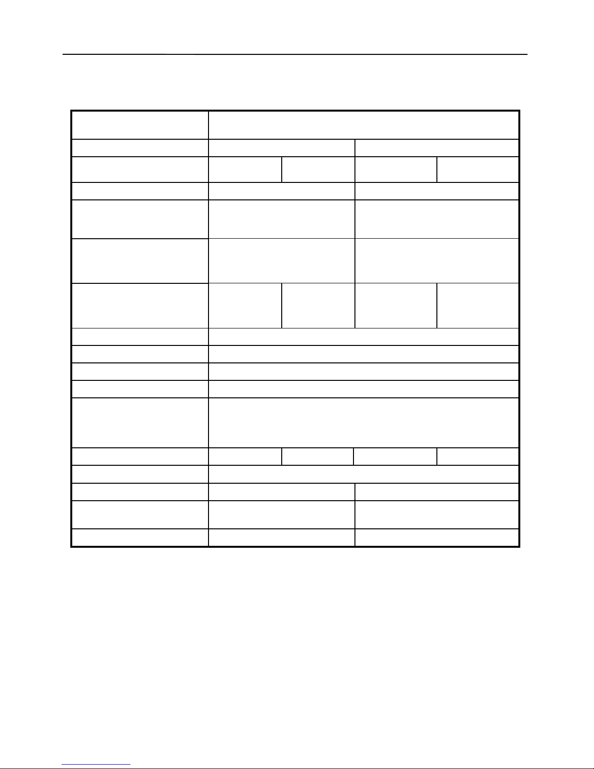
5 Technical Data*
Series
INTEGRA Bi-Voltage version
Model type 250 500
Values attained at:
230V/
50 Hz
115V/
60 Hz
230V/
50 Hz
115V/
60 Hz
Rated energy: 250 J 500 J
Aperture at 100 ASA, t 1/60,
1 m distance, Maxi Soft Reflector, Glass dome clear:
f 64 4/10
f 90 4/10
Flash duration (sec.)
t 0,1:
t 0,5:
1/600
1/1800
1/420
1/1300
Recycle (sec.)
to 100%:
to 1/16:
1,2
0,3
1,8
0,4
2,1
0,6
1,8
0,4
Flashtube: U-Tube, user replaceable, single coated
Power adjustment: steplessly 5 f adjustable (1/1 ... 1/16)
Modeling lamp max.: 300W / G6,35 Halogen
Modeling light adjustment: switchable to FULL, OFF or PROP over a range of 5 f
Features: Glass Dome (clear, uncoated),
Flashtube (user replaceable, single coated),
Fan, Tilting Head with integrated Umbrella Holder;
Additional types of glass domes for colour correction as accessory
Fuse: 2 AF 4 AF 2 AF 4 AF
Mains connection:
manual switchable: 230 V∼ /115 V∼
Weight (kg): 2,0 2,1
Measurements (LxWxH)
in cm:
31 x 12,6 x 19,7
31 x 12,6 x 19,7
Code No.: 8802 8812
*: Technical changes reserved.
Page 10

user manual INTEGRA
HENSEL Studiotechnik 8
6 Overview of Controls
1 ON:
Main Switch ON / OFF
2 FC:
Flash Check ON / OFF
3 Slave ON Indicator
4 READY:
Ready (for flash triggering) and Overheat Indicator
5 SLAVE:
Slave ON / OFF
6 TEST:
Manual flash release
7 230V/50-60 Hz / 115V/50-60 Hz:
Mains Connector
8 FULL / OFF / PROP:
Operation mode for modeling lamp
9 Flash Power control switch
10 Fuse for modeling lamp
11 Sliding switch
230 V / 115 V mains voltage
12 SYNC:
Synchronisation Socket
13 Slave
14 Reflector Quick-Change Mechanism
15 Tilting Head with integrated Umbrella Holder
7 Starting Up
Safety hints for operation with compact flash units
To avoid damage to the flashtube mount reflectors and
lightformers (softboxes etc.) before
use and turning on the
unit. Do not move compact flashes around, while they are
operating. Turn off the appliance for each change of reflectors
or to move the unit to another location.
Caution:
Reflectors, speedrings and other accessories heat up during
longer operation. To avoid injuries, handle with isolating cloth
or wait, till parts cooled down.
Page 11

user manual INTEGRA
HENSEL Studiotechnik 9
A damaged flashtube is extremely dangerous because
the electrically charged electrodes are exposed and
touching must be avoided; the unit must be switched off
and disconnected
from the mains outlet immediately. The
capacitors inside may still be charged and dangerous
high voltage can still be present at the damaged flashtube
electrodes (Replacement see page 15, Maintenance).
Assembly
When mounting to a ceiling system or a pantograph,
suspended compact flash has to be double secured from
falling down or dropping. This is done by tightening the safety
screw (not included in the standard delivery) into the thread of
the HENSEL Tilting Head.
Due to the existing safety regulations, it is, however,
necessary to use a safety rope (code no. 769) for further
security.
The safety rope has to be led through the handle of the
compact flash and then secured by looping through the
bracket on the pantograph or the eyelet on the carriage.
Heating
Due to the modeling and flash light, each compact flash unit
emits heat. This can heat up the parts of the unit to a
dangerous level.
Therefore make sure, that the flash unit is located far enough
from inflammable props to avoid inflaming them.
Take care for sufficient air supply and make sure that
ventilation slots of compact flash units are kept free.
Do not operate flash units unattended.
The modeling light should never be used for lighting up the
studio but only as an assistance when focusing or determining
the light guiding and shadow details of the flash.
Acclimatizing
When moving the flash unit from one climatic zone to the next,
the appliance should stand in the room, in which it will be
operated, for some time before starting it up. This prevents
possible surface leakage currents due to condensing water.
Page 12
user manual INTEGRA
HENSEL Studiotechnik 10
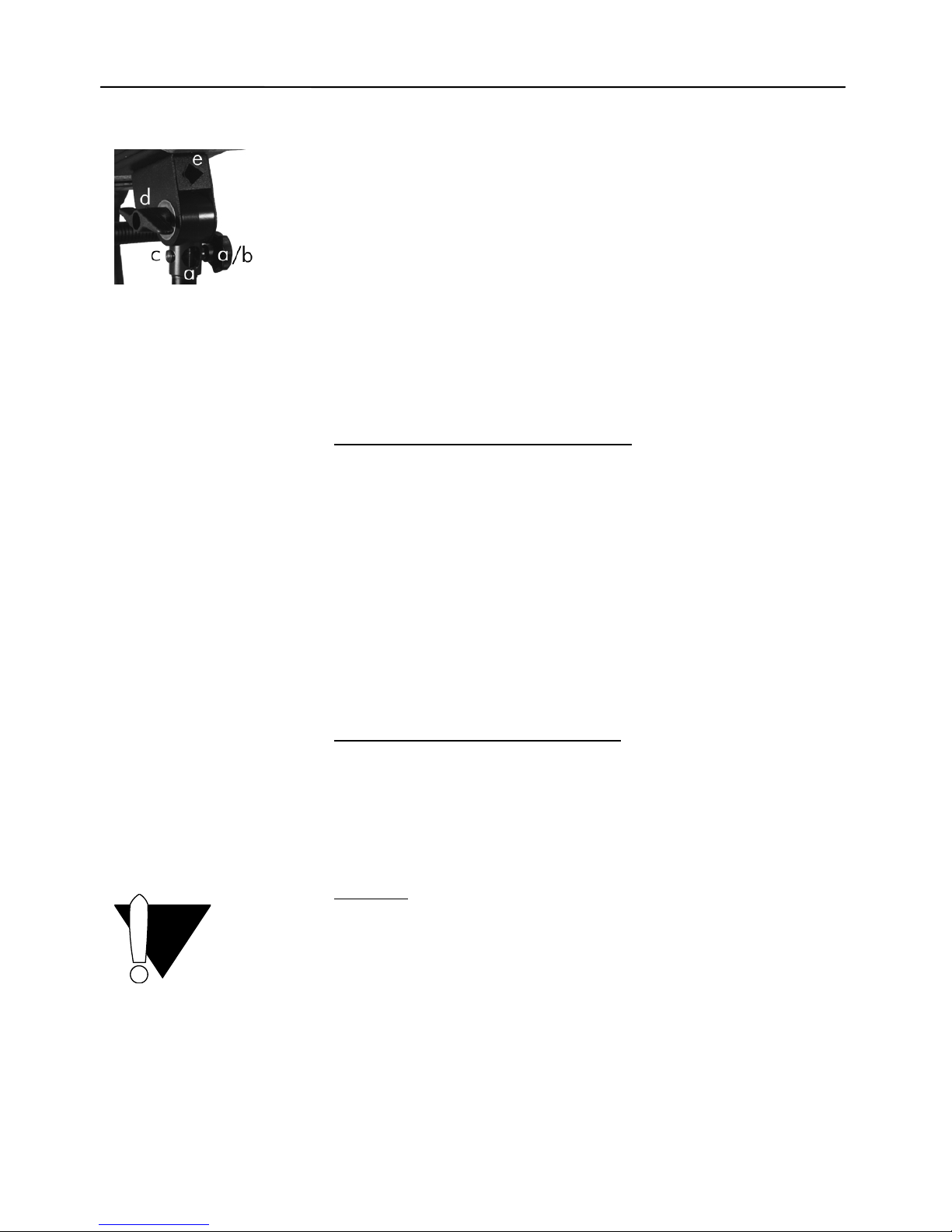
Tilting Head 15:
Positioning
INTEGRA compact flash units are equipped with a Tilting Head
15. The unit can be attached to a stand or pantographs using
one of the two holes a. The head can be swivelled round 360°.
By tightening the knurl screw b the unit can be fixed. The safety
screw must be screwed into thread c. Wing nut d guarantees
for tilting up and down. To ensure smooth movement please oil
the threat if necessary. Above the tillting head an umbrella
holder e is integrated.
Accessories
All HENSEL reflectors and HENSEL softboxes of series EHT
(adapter Ø: 10 cm), accessories included, may be attached to
the INTEGRA compact flash; also umbrellas and Softstar.
Assembly of reflectors and softboxes
For fixing reflectors or softboxes to the compact flash unit,
please first of all open the holding clamps. For doing this,
please tension lever 14 laterally as far as it will go against the
spring tension. While doing this, the holding clamps will open.
Now even and precisely attach the accessory part to the unit.
Please do not tilt. By releasing the lever, the holding clamps
will completely enclose the accessory part.
For loosening the accessory, please hold tight the accessory
part (Attention - it could be hot!) and tension lever 14 again as
described above.
In any case please make sure not to damage either the
flashtube or the modeling lamp (danger!).
Assembly of umbrellas and Softstar
An umbrella holder is integrated above the tilting head 15. It
allows for the connection of various umbrellas by using a strong
gripping spring mechanism.
No screw is required, which could cause damage to the
umbrella.
Fixing of the glass dome
Attention
:
The glass dome should only be fixed or removed after having
switched off the unit and unplugged from the mains outlet.
Please take care not to damage either the flashtube or the
modeling lamp (danger!).
The glass dome is fixed by means of the three pre-mounted
springs. For doing this, please slightly tilt the glass dome and
insert it into one of the three springs. Then press the glass
dome gently into the other two springs until it has completely
clicked in.
Page 13

user manual INTEGRA
HENSEL Studiotechnik 11
10 A
Bi-Voltage/230V:
2 AF
Bi-Voltage/115V:
4 AF
For removing the glass dome, please slightly tilt it again so
that it will easily slip out of the two fixing springs.
Then gently loose the glass dome from the remaining third
spring and remove it from the fixing device.
Mains connection
Attention:
Before connecting the compact flash unit to the mains outlet,
make sure, the mains voltage matches the information given on
the type label of the compact flash. The type label can be found
on the bottom of the appliance.
When you are operating with INTEGRA Bi-Voltage, make sure
that depending on the mains voltage the sliding switch 11 is in
the correct position.
The provided power cable will be attached to the mains socket
7 and then connected to mains outlets.
Compact flashes may only be connected to mains outlets
with ground connection.
Fuses
Outlets, in the building
Minimum requirement 10 A fuse outlets
Fuses of INTEGRA
The fuse 10 is a general fuse for the compact flash unit and the
modeling lamp.
Fuses listed below are valid for operation with modeling light
300 W Halogen:
For operation at 230 V mains voltage the Bi-Voltage version
must be equipped with a fuse 2 A fast (2 AF), for operation at
115 V mains voltage with a fuse 4 A fast (4 AF).
Before starting up the Bi-Voltage version check the
provided fuse! Make sure, that the position of the sliding
switch 11 corresponds to the mains voltage.
More information on page 14, Replacement of fuses.
Page 14

user manual INTEGRA
HENSEL Studiotechnik 12
READY
SYNC
SLAVE
receiver and
transmitter
„Speed“
Overheating
All INTEGRA units are equipped with a fan to avoid overheating
with fast flash sequences, which could cause damage to the
flashtube and the compact flash unit. If overheating although
occurs, the unit turns off automatically. The red light of the
Overheat Indicator 4 turns on. After a break for cooling down,
the appliance is ready again for operation.
8 Operation
Synchronization (Flash triggering)
Synchronization by cable
The compact flash unit is connected to synchronization socket
12 to the camera using a synchronization cable with 6,3 mm
phone jack.
The synchronization circuit is made up of state-of-the-art semiconductor technology and enables secure triggering of the flash
even with older cameras with mechanical contacts.
Due to the many different electronical circuits in cameras for
controlling synchronization, we cannot take any liability for
possible damage to cameras triggering flashes.
Please contact the camera manufacturer before using an
unusual camera.
Synchronization by slave
The compact flash unit can be triggered by the built-in slave 13.
Triggering is then effected by an „incoming“ flash, which was
emitted by another flash light. This mode of operation is
switched on using switch 5 and displayed by the yellow light of
the SLAVE ON Indicator 3.
The slave is an impulse photocell. It can only operate, when the
triggering flash has a higher f-stop than the ambient light.
Please be aware that the ambient light which strikes the slave
may never be too strong. If this cannot be avoided, please
switch off the slave by pressing switch 5 and release the flash
by cable or IR.
Synchronization by infrared triggering system
For remote-controlled triggering, an infrared triggering system is
available as accessory:
IR Transmitter and Receiver „Speed“
Code 392 (Set) or 393 (Transmitter) + 394 (Receiver)
Page 15

user manual INTEGRA
HENSEL Studiotechnik 13
TEST
READY
OFF
PROP
FULL
FC
The IR transmitter „Speed“ has to be attached to the camera.
The IR group A or B can be selected on the transmitter by a
slide switch.
The IR receiver „Speed“ has to be connected to the
synchronization socket 12. The same IR group A or B must be
set on the receiver by a slide switch.
Flashes can be triggered using the provided synchronization
cable or the camera hot shoe. The transmitter should
approximately be pointed towards the connected IR-receiver.
All compact flashes within one selected group are flashing.
Test flash
By pressing the button 6 test flashes can be released.
Flash power control
The desired flash power can be set steplessly using power
control 9. This covers a range of 5 f-stops.
Flash readiness
Flash readiness of the compact flash is shown by the green
light of the READY control lamp 4.
In the case of reducing the flash power, the yellow light of the
READY Indicator 4 turns on, till the flash power has been
dumped to the new level (READY Indicator green). It is also
possible, to reduce the stored energy by simply triggering a
TEST flash (press button 6).
Modeling lamp
You can select the operation mode for the modeling light by
positioning switch 8:
OFF
The modeling lamp is switched off.
PROP
The light output is proportional to the selected flash power.
FULL
The maximum light output of the modeling lamp is achieved.
Flash Check
If this mode is switched on turning switch 2 to „FC“ position,
then the modeling lamp is turned off after a flash and will turn
on after recharging to the adjusted power level. This shows
correct charge as well as readiness to flash. The flash check
mode guarantees that the flash heads have triggered when
more than one flash unit is used.
Page 16
user manual INTEGRA
HENSEL Studiotechnik 14
9 Maintenance
The INTEGRA compact flash is in need of little maintenance by
the user. The unit should be dry
cleaned from dust from time to
time. Before cleaning separate the unit from the mains outlet.
Caution
:
Under no circumstances is any part of the equipment to be
opened. The equipment is not user serviceable and there is
dangerous high voltage. In the event of difficulty notify your
dealer.
Replacement of fuses
In case of a broken fuse 10 replace fuse only, when the unit is
switched off and separated from the mains outlet.
Attention
: Never repair or bridge fuses.
Only use “fast” fuses with the required values:
Fuse for Code No.
INTEGRA 250 Bi-Voltage/230V operation: 2 AF
INTEGRA 250 Bi-Voltage/115V operation: 4 AF
INTEGRA 500 Bi-Voltage/230V operation: 2 AF
INTEGRA 500 Bi-Voltage/115V operation: 4 AF
Only use fuses in accordance with EN 60127-2/1 and
IEC 127-2/1, respectively. A wrong fuse may cause an
explosion of the halogen modeling lamp.
Before starting up check the provided fuse! Make sure, that
the position of the sliding switch 11 corresponds to the
mains voltage.
Replacement of modeling lamp
Replace modeling lamp only, when unit is switched off and
unplugged from the mains outlet.
Make sure that the modeling lamp is protected by the specified
fuse (see paragraph replacement of fuses above).
For all types of INTEGRA compact flash units only use
max. 300 W / G 6,35 Halogen
as modeling light.
For order please look up the Code No. in the following table.
Page 17
user manual INTEGRA
HENSEL Studiotechnik 15
Modeling lamp 300 W Halogen for Code No.
INTEGRA 250 Bi-Voltage/230V operation: 128
INTEGRA 250 Bi-Voltage/115V operation: 1280
INTEGRA 500 Bi-Voltage/230V operation: 128
INTEGRA 500 Bi-Voltage/115V operation: 1280
Wait till modeling lamp has cooled down, and then carefully
remove the glass dome from the unit by pulling it out of the
spring mechanism (see page 10) and moving it straight away
without touching modeling lamp or flashtube (danger!).
Handle halogen lamp with care because of the high pressure
inside. Pull out halogen lamp and replace the modeling lamp
with a new one.
Avoid touching the halogen lamp with your fingers; this causes
a higher risk of explosion of the halogen lamp.
Replacement of flashtube
All unit types of INTEGRA are equipped with a user replaceable
flashtube.
For replacement of flashtube switch off the unit, separate it
from the mains outlet and wait for at least 15 minutes.
Then carefully remove glass dome from head by pulling it out of
the spring mechanism (see page 10) and moving it straight
away from the head without touching modeling lamp or
flashtube (danger!).
Handle flashtube with care because of the high pressure inside.
Caution
: In case of a damaged flashtube glass the electrodes of
the tube must not be touched in any case! In this case it is a
must to use isolated pliers for pulling out the flashtube!
First unwind the ignition cable from the connection pin of the
ignition. Then pull out flashtube and replace it with a new one.
Finally connect the ignition cable.
You must make sure that the appropriate flashtube is used.
Please order from HENSEL:
Flashtube, user replaceable, for INTEGRA Compact,
single coated, Code No. 9450401.
Page 18

user manual INTEGRA
HENSEL Studiotechnik 16
Regular inspection
National safety regulations require regular inspection and
maintenance of electrical systems and appliances. Compact
flash units and accessories must be regularly checked for safe
operation. Yearly inspection of the appliances serves the safety
of the user and protects your investment in the system.
Return to customer service
To achieve a maximum protection of the unit sending it in for
service, the original packaging should be kept.
10 Disposal
Packaging of the compact flash unit must be separately
disposed of and recycled. Worn out and broken appliances
must be disposed of by electronics recycling.
11 Accessories
Glass Domes
Code No. 9454638: clear, uncoated
Code No. 9454637: clear, single coated
Code No. 9454639: frosted, uncoated
Flashtube, user replaceable
Code No. 9450401: U-Tube, single coated
Reflectors and Softboxes
with small accessory adapter diameter (10 cm)
for series EHT/EXPERT/CONTRA
Umbrellas
12 Customer Service
Works customer service
with 24 hours express service:
HENSEL Studiotechnik GmbH & Co. KG GERMANY
- service department -
Robert-Bunsen-Str. 3
D-97076 Würzburg
Phone: +49(0)931/27881-0
Fax: +49(0)931/27881-50
e-mail:
Page 19

user manual INTEGRA
HENSEL Studiotechnik 17
13 Ce rt i f ic a t e o f Co n f o rm i t y
for Electromagnetic Compatibility and Safety
Manufacturer and HENSEL Studiotechnik GmbH & Co.KG
Owner of Certification: Robert-Bunsen-Str. 3
97076 Würzburg
Germany
Test Report: of October 27, 1999
Product: Compact Flash Units
INTEGRA 250 / INTEGRA 500
Description: Emission and Interference Resistance
Directives: EN 50 081-1 / EN 55 014 / EN 60 555 /
EN 50 082-2 / EN 61 000-4-2/3/4/5
This certificate of conformity is made by the above mentioned manufacturer according to article
10, paragraph 1, of the Councils Directive of March 3
rd
1989 referring to electromagnetic
compatibility and safety for bringing the statutory instruments of the Member States into lines with
each other. This certificate does not make any statement according to requirements of other
provisions concerning the electromagnetic compatibility and safety.
Description: Low Voltage Directive
Directives: EN 60491:95 / EN 60598-1:93+A1:96 /
EN 60598-2-9:89
This certificate of conformity is made by the above mentioned manufacturer according to article
10, paragraph 1, of the Councils Directive of February 19
th
1973 referring to electrical items for
usage within specified voltage limits (72/23/EWG).
This certificate of conformity is the result of testing samples of the above listed products submitted,
in accordance with the provisions of the relevant specific standards.
Date: October 27, 1999
Manufacturer
J. Renschke
- Managing Director HENSEL Studiotechnik GmbH & Co.KG
Page 20
Weitere Produkte von HENSEL Studiotechnik
Other products of HENSEL Studiotechnik
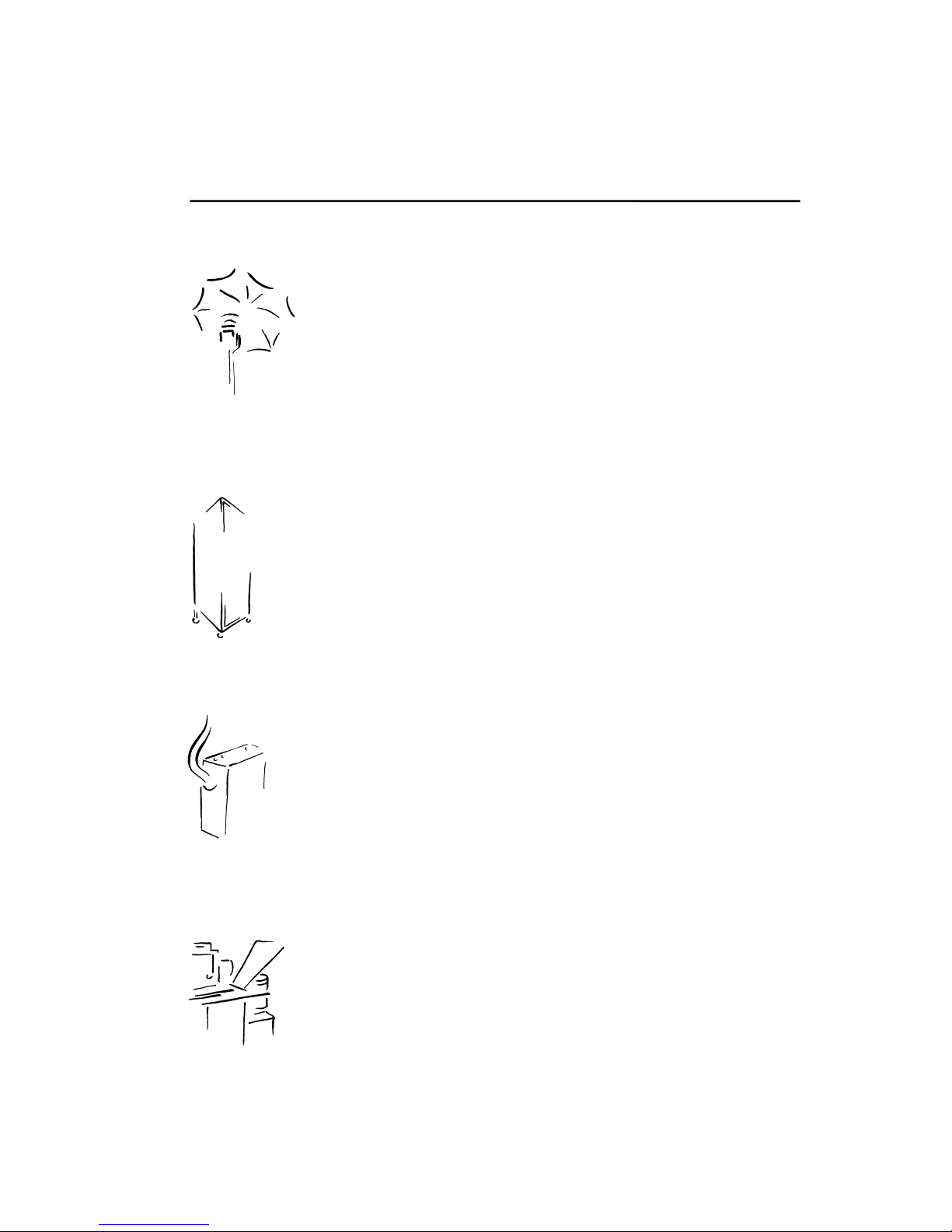
Reflexschirme
Umbrellas
Lichtwannen, Softboxen
Autolights, Soft Boxes
PORTY
akkubetriebener Generator
Battery powered generator
Frontprojektion
Frontprojection
 Loading...