

Page 1

TM
USB MATCHBOX II
USB<>XLR MULTIMODE DIGITAL AUDIO CODEC
DESCRIPTION
The USB Matchbox II is a high-performance professional audio codec. Used in place of a computer “sound card”, it
provides stereo analog inputs and outputs at professional studio levels, an AES/EBU output, and a Headphone
output for critical monitoring. The USB Matchbox II yields superb “audiophile” performance with the convenience of
USB interface to any Windows, Mac, or Linux based computer. The USB Matchbox II is compatible with virtually
any audio recording/editing software that supports a USB sound device. No special software or driver is needed.
A USB 1.1 (or higher) connection to the PC is required. The USB Matchbox II complies with the AES-48-2005
grounding standard.
INSTALLATION
ANALOG LINE INPUTS/OUTPUTS: Connect balanced analog inputs and output to the XLR connectors as follows:
Pin 1 = GND, Pin 2 = HI, Pin 3 = LOW.
NOTE: Ground loops cause hum, buzz, and other noises that are created by the computer mouse, drives, fan, and
keyboard. Prevent noise by connecting ground wires at one end only.
The HEADPHONE output can be used to monitor the “play” output of the system. Use contemporary headphones
with an impedance of 24 ohms or greater. Do NOT use older “8 ohm” headphones. The VOLUME control adjusts
the headphone level. Warning! Excessive listening levels can cause permanent hearing damage.
DIGITAL OUTPUT: Connect to the AES/EBU digital output XLR connector as follows:
Pin 1 = GND, Pin 2 = HI, Pin 3 = LOW. (The AES/EBU output is transformer isolated.)
COMPUTER CONNECTION:
First, close any audio-related programs. Use a USB cable to connect the USB Matchbox II to any USB port on the
PC. The computer should recognize the USB Matchbox II as “USB Audio Codec”. No additional software or
drivers are needed. When audio software is started, it may be necessary to change its Settings to select the
USB Audio Codec as its default.
WINDOWS* VOLUME SETTING
BEFORE USING USB MATCHBOX II
Volume can be accessed via the Windows Control Panel under “Sound and audio devices” or “Adjust the system
volume”. Select “Volume” or “Set system volume”, then adjust the slider. In most cases, the Speaker Volume
should be set to MAXIMUM.
OUTPUT LEVEL CALIBRATION
The USB Matchbox II is calibrated to operate with analog I/O levels of +4 dBu. Input and Output levels can be
changed via the recessed trimmers; use a small screwdriver to carefully adjust. NOTE: There is 15 dB of digital
headroom above +4 dBu: a calibration tone recorded at 0 dBfs will produce an output level of about +19 dBu.
OPERATION
To record, feed audio into the unit. Set the INPUT LEVEL trimmers as necessary, as indicated by the software
being used. To play a recording, simply play the file. Audio will be present on the XLR analog outputs, Headphone
jack, and on the AES/EBU digital output. (The Headphone output monitors “playback” audio only.)
SPECIFICATIONS
Balanced analog inputs Stereo, nom. +4 dBu @ -15 dBfs, 20K ohms input impedance, XLR X 2
Balanced analog outputs Stereo, nom. +4 dBu @ -15 dBfs, +24 dBu max level, 600 ohms, XLR X 2
AES/EBU digital output Transformer isolated, 110 ohms, XLR connector
Headphones output For headphones, 24 ohms or higher; 3.5mm stereo jack
Sample rates supported 48, 44.1, or 32 kHz, software defined
Resolution, dynamic range 16 bit stereo or mono, software defined
USB supported USB 1.1 or higher
Power Input 115 or 230 VAC, 50-60 Hz, 2W, + USB power
Approval City of Los Angeles Electrical Test Lab
Physical 5.75” w X 5.50”d X 1.60”h, 3 LBS
Construction Steel enclosure
, be sure to check the Windows “SPEAKER VOLUME” setting. The Speaker
*Windows is a registered trademark of Microsoft Corporation.
HENRY ENGINEERING
503 Key Vista Drive
Sierra Madre, CA 91024
Tel: 626.355.3656
Fax: 626.355.0077
www.henryeng.com
Page 2
5
J1
R3 4.99K
IN L
D D
J2
3
2
1
NC3FAH2
C2
.001uF
R1 10.0K
R2 10.0K
C3
.001uF
R4
4.99K
-15V
U1A
-
+
8 4
+15V
NE5532
1
VR2
1K 40%
2
3
R6 200
USB
REC L
2
1 3
R10 4.99K
IN R
J3
3
2
1
NC3FAH2
C C
C5
.001uF
R12 10.0K
R11 10.0K
C4
.001uF
R9
4.99K
R29
200
B B
+15V
-15V
U1B
-
6
5
NE5532
7
+
+15V
8 4
R7 200 R27
VR3
1K 40%
2
REC R
1 3
R30 2.4K
-15V
2
3
-
+
U5
LM6181
7 4
C19
.1uF
6
R31
110, 1/4W
C20
.1uF
1
2
3
4
C9
.1uF
4
T2
TC-615
1 3
2 4
+15V
-15V
J7
1 2
3 4
5 6
7 8
9 10
11 12
13 14
15 16
17 18
19 20
21 22
23 24
25 26
27 28
29 30
31 32
33 34
35 36
37 38
39 40
J6
AES OUT
3
2
1
NC3MAH
3
PLAY L
VR4
1K 40%
R20
200
PLAY R
VR5
1K 40%
R40
200
C15 .22uF
2
1 3
C14 .22uF
2
1 3
+
C1 22uF
C17
.1uF
C18
.1uF
+
C7 22uF
R14
4.99K
4.99K
C6 30pF
R15 20.0K
-15V
-
+
8 4
NE5532
+15V
2
3
R16 4.99K
R17 4.99K
-15V
-
6
5
NE5532
+
+15V
8 4
C8 30pF
R26 20.0K
-15V
-
+
8 4
NE5532
+15V
2
3
R25 4.99K
R24 4.99K
-15V
-
6
5
NE5532
+
+15V
8 4
C21 30pF
U2A
1
U2B
7
U3A
1
U3B
7
2
R18
47, 1/4W
R19
47, 1/4W
R23
47, 1/4W
R22
47, 1/4W
J4
3
2
1
NC3MAH
J5
3
2
1
NC3MAH
1
OUT L
OUT R
R37 20.0K
LED1 LED
R21
-15V
-
2
3
NE5532
+
+15V
8 4
C13 30pF
R36 20.0K
-15V
-
6
5
NE5532
+
+15V
8 4
U4A
1
U4B
7
R38
47, 1/4W
R39
47, 1/4W
2
C10
+
220uF
C22
+
220uF
E10
E11
E12
HP-L
HP-G
HP-R
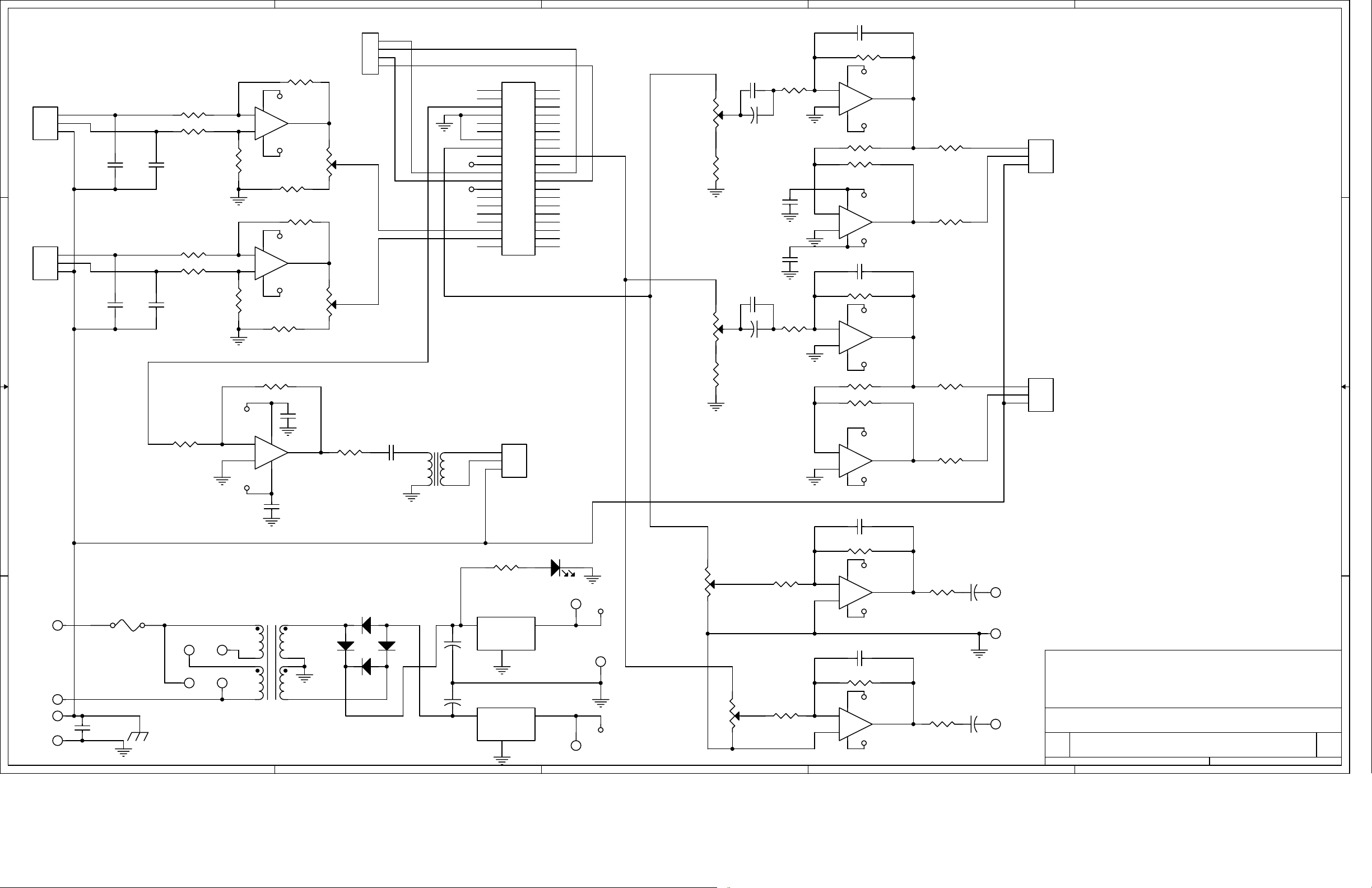
Title
SCHEMATIC: USB MATCH BOX II
Size Document Number Rev
B
5400 A
Date: Sheet
6
VR1B
10K, 18%
5 1
R34 4.99K
R35 4.99K
3.9K, 5%
1
TP1
1
+15V
PHONES
LEVEL
1
-15V
D2
D4
1N4004
D3
1N4004
1N4004
E1
E2
BLK
115V: 250 ma;
230V:125ma
WHT
F1
E8
E7
115V
230V
AC
A A
AC
E4
GROUND TIE
E5
C16
.01uF
1
PRI SEC
E6
2
3
E9
4
T1
SPW-061
5
1N4004
6
7
8
C12
1000uF 35V
D1
C11
1000uF 35V
Q1 LM7815
3
+
+
IN
Q2 LM7915
2 3
IN OUT
OUT
GND
2
GND
TP2
1
TP3
3
VR1A
10K, 18%
4 2
1
5
4
3
NOTE: UNLESS OTHERWISE SPECIFIED
1. ALL RESISTORS ARE 1/8W, 1%.
HENRY ENGINEERING
503 Key Vista Drive
Sierra Madre, CA 91024 USA
telephone - (626) 355-3656
FAX (626) 355-0077
of
1
11Monday, December 01, 2008
 Loading...