

Page 1

HENRY ENGINEERING
SUPERELAY II
Seal Beach, CA 90740
UTILITY CONTROL INTERFACE
DESCRIPTION
SUPERELAY II is a utility control interface that provides switching and control functions in a broadcast studio, control
room, A/V system, or any installation requiring multiple circuit control. Superelay II provides three types of outputs:
isolated relay contacts, switched AC, and switched DC. Six SPDT relay contacts can be used for audio, low voltage, or
"dry circuit" switching. The switched AC output can control up to 200 watts of AC load. The switched DC output can
supply 12 vdc at up to 300 ma; it can also “sink” up to 1 amp if used with an external power source. Both switched AC and
DC outputs can be set to “flash” when ON for use with ON THE AIR warning lights. All control, relay output, and DC
output connections are via plug-in euroblock connectors. The AC output is via a standard three-prong grounded outlet.
WARNING! For 230V operation, change mains voltage jumpers before connecting to AC power!
Remove jumpers between E6 & E7, and between E5 & E8. Install a jumper between E5 & E6 for 230V; replace fuse F1
with .125a fuse. See schematic on reverse side. Jumpers should be changed by a qualified technician only.
INSTALLATION
Connection to Control inputs and low voltage relays is via plug-in connectors. Remove about 1/8” of the insulation, insert
wires into the connector, and tighten the screws. Be sure that no bare wires are exposed.
CONTROL INPUTS: Superelay can be switched ON and OFF by either a momentary or maintained ground closure, or by
application of an external DC voltage.
For control with a ground closure: A momentary closure between the ON and G terminals will turn the unit ON.
A momentary closure between OFF and G will reset it OFF.
For control with a maintained closure install a jumper between the OFF and G terminals.
A maintained closure between ON and G will turn the unit ON; removing the closure will reset it OFF.
The ground closure can be a relay or switch contact, open collector, CMOS or TTL gate, opto-isolator, or any other circuit
that switches to ground. The red TALLY-ON LED will light to indicate the ON state.
For control with a DC voltage: Superelay can be controlled by applying an external DC voltage to the IN+ and G
terminals. Any DC voltage between 5 and 24 volts will switch the unit ON. This input is opto-isolated. Observe polarity.
RELAY OUTPUTS: Superelay provides six SPDT relay contacts for utility use. All six relays operate simultaneously. The
C and NO terminals are active when then unit is ON; the C and NC terminals are active when the unit is OFF. These
relays can switch up to 1 amp at 24 volts DC. (Do NOT use these relay outputs to switch AC line voltage!)
AC TALLY LIGHT OUTPUT: Superelay also provides a TALLY output that supplies AC line voltage for incandescent
warning lights when the unit is ON. (Do not use florescent lights.) The TALLY output will flash if the front panel FLASH
switch is set to ON. The Tally output load should not exceed 200 watts. The TALLLY LIGHTS FUSE, accessible from the
rear panel, will blow if this limit is exceeded. (Replace with a 2A AGC fuse.) Note: The low voltage relays will continue to
operate even if the Tally Lights fuse blows.
NOTE: It is normal for there to be a slight amount of leakage current through the AC output if no output load is plugged into the AC socket.
If the AC output is measured with an AC voltmeter, it will show line voltage present even if the unit is OFF. This is normal; plugging a light bulb or other
load into the AC socket will eliminate this false reading.
LED TALLY LIGHT OUTPUT: Superelay can control low-voltage LED Tally lights. The unit can directly power LED Tally
lights that require 12 vdc, 300 ma or less. Connect the Superelay 12V terminal to the + wire of the light; connect the
– wire of the light to the LED terminal on the Superelay.
For LED Tally lights that require more than 12 vdc or 300 ma, use an external power source connected as follows:
Connect the + voltage source directly to the + wire of the light. Connect the ground of the power source to the G terminal
of the Superelay, and connect the – wire of the light to the LED terminal on the Superelay.
The 12V terminal provides 12 volts DC for utility use, 300 ma maximum.
Rev. D: 9/2015
PO Box 3796
Tel: 562.493.3589
www.henryeng.com
Page 2
11
NONE
CHECKED:
DATED:
J. SWANSON
DRAWN:
DATED:
DRAWING NO:
COMPANY:
SHEET: OF
B
REV:SIZE:
TITLE:
SCALE:
REVISION RECORD
APPROVED:ECO NO:
A
B
D
DATE:
C
LTR
D
6
54321
C
B
A
D
MODEL:
SECPRI
BLK
115V
230V
AC
AC
WHT
1. ALL RESISTORS ARE 1/4W, 5%.
NOTE: UNLESS OTHERWISE SPECIFIED
GRN
AC
AC
TALLY OUTPUT
BLK
WHT
C12
NO
NO
C
NC
C
NC
3
4
NO
NO
C
NC
C
NC
5
6
NO
NO
C
NC
RELAY OUTPUT RELAY OUTPUT RELAY OUTPUT
CONTROL
NC
ON
OFF
GND
DC
+12V
LED
HENRY ENGINEERING
PO Box 3796
Seal Beach, CA 90740
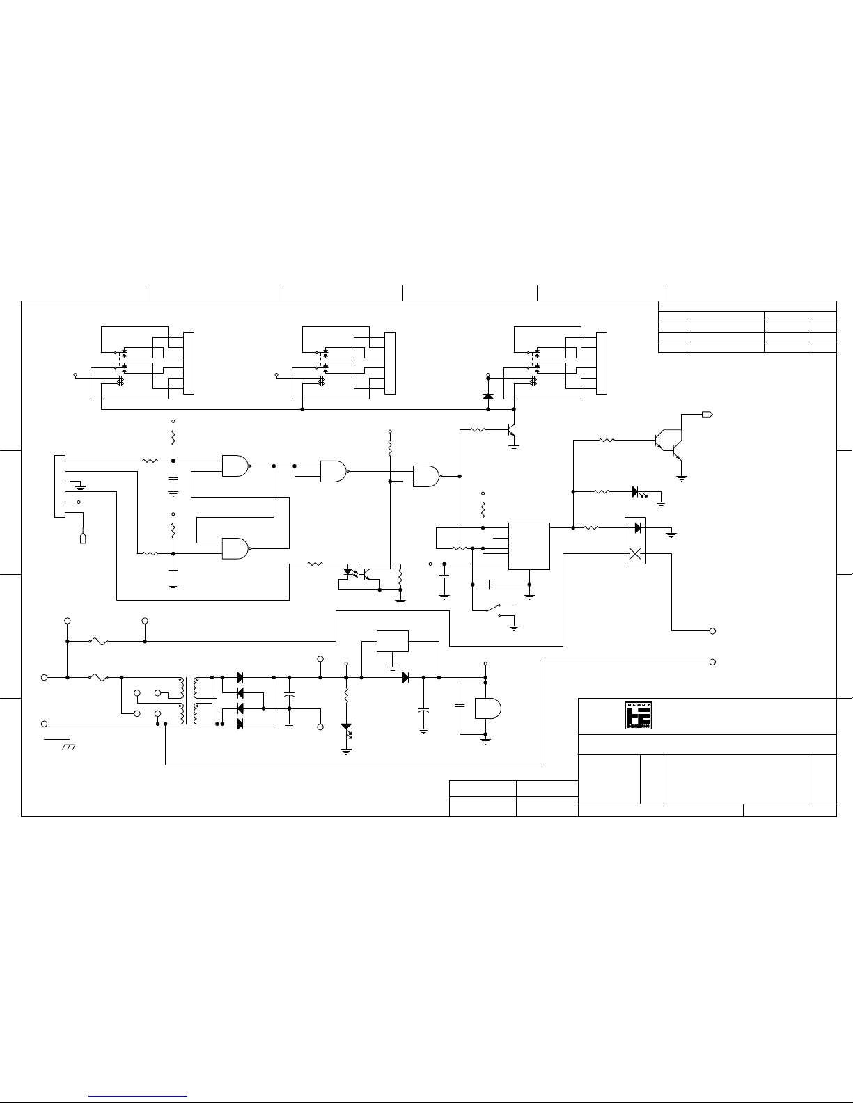
Tel: 562-493-3589
SCHEMATIC: SUPERELAY
4000
HE_PN4000 SCHEMATIC
F2-TIP F2-SIDE
9/25/15
3
OUT
4
RST
8
VCC
1
GND
5
CV
2
TRG
6
THR
7
DSCHG
U2 NE555N
1
2
3
4
5
6
J2
D3
1N4004
E3
+
C1
2000uF 25V
C3
.1uF 50V
E4
R8
3 MEG
E7
E1
C6
.1uF 50V
4
6
8
13
11
9
1
16
K3
DPDT 12VDC
R10
1 MEG
Q1
2N4401
C5
1uF 100V
R5
47K
F2
2 AMP
1
TP2
2
1
3
SW1
LED2
LED
E8
E2
R4
47K
R7 220K
LED1
1
2
3
4
5
6
J1
1
2
3
4
5
6
J4
1
2
3
4
5
6
J3
1
TP1
R3
10K
R2 100
R11 1.5K
C2
.1uF 50V
R6
10K
R9 1.5K
R1 100
D2
1N4004
E5
F1
115V: 250 ma; 230V: 125ma
4
6
8
13
11
9
1
16
K1
DPDT 12VDC
1
3
4
256
8
7
T1
SPW-153
21
34
K4
SPST 2A
12
R13
100
C4
.1uF 50V
R12
1.5K
16
2
5
4
U3
4N25
D1
1N4004
E6
4
6
8
13
11
9
1
16
K2
DPDT 12VDC
D4
1N4004
+
C7
2000uF 25V
1
2
3
U1-A
CD4011
5
6
4
U1-B
CD4011
8
9
10
U1-C
CD4011
12
13
11
U1-D
CD4011
7
GND
14
VCC
U1-E
CD4011
R14
1.5K
3
E
1
B
2
C
Q2
TIP120
3
IN
2
GND
1
OUT
Q3
LM78L05ACZ
E9 E10
D5
1N4004
D6
1N4004
+12V
+12V
VCC
VCC
VCC
VCC
VCC
+12V +12V +12V
VCC
A
A
 Loading...