

Page 1

TM
STUDIODRIVE
Integrated PC Studio System
HENRY ENGINEERING
503 Key Vista Drive
Sierra Madre, CA 91024
Tel: 626.355.3656
Fax: 626.355.0077
www.henryeng.com
1.0 DESCRIPTION
StudioDrive is a professional stereo audio system that can be installed in the drive bay of a personal computer
(PC). StudioDrive provides the source control, mixing, and monitoring functions of a professional broadcast audio
console to create a complete self-contained studio that is ideal for live broadcasting and audio production tasks.
StudioDrive accepts up to 6 audio sources via 4 mixing channels. There are inputs for a studio microphone, three
stereo line level sources, a dedicated input for the PC soundcard, and the built-in telecoupler for recording audio
(news feeds, actualities) from a standard POTS line.
StudioDrive has two pair of stereo outputs for live broadcasting and recording to the PC soundcard or other
recording device. Accurate LED VU meters monitor the Program output level. A monaural Mix-Minus output is
provided for use with any external telephone hybrid.
The Monitor and Headphone system allows StudioDrive to monitor (a) the Program output, (b) playback from the
soundcard or (c) the off-the-air signal from the station demodulator.
StudioDrive consists of the main control unit which is installed in the PC’s drive bay, and the Audio Interface unit
that contains the power supply and all I/O connections. The Audio Interface unit can be attached to the back of the
computer case or mounted to a tabletop or wall. The two units are interconnected with a flat cable, which is routed
through the back of the computer. An optional Desk Mounting Kit allows StudioDrive to be desk-mounted, for use
with a laptop computer (or for non-PC applications) or if it is not possible to mount the main control unit in the PC.
Any soundcard with either balanced (professional) or unbalanced (consumer) analog I/O can be used with
StudioDrive to create an integrated and self-contained broadcast and production facility.
2.0 INSTALLATION StudioDrive should be installed by a qualified engineer or technician.
StudioDrive can be installed in the drive bay of a PC or desk mounted using the optional Desk Mounting Kit.
Before installing StudioDrive in the PC, the complete system should be programmed, connected, and calibrated to
all peripheral studio equipment. Only after proper operation is verified should StudioDrive be installed in the PC.
2.1 USER PROGRAMMING
Before StudioDrive is installed, the user must set some internal jumpers to optimize the unit for the peripheral
equipment with which it will be used. JP1 thru JP9 are located on the StudioDrive circuit board.
JP1 and JP2 set the input sensitivity for Line Input #2. Set them to HI if the source equipment is balanced and
operates at about 0 dBu. Set them to LO if the source is unbalanced and operates at -10 dBv.
JP3 and JP4 set the input sensitivity for the PC soundcard (playback) inputs. Set them to HI if the PC soundcard is
balanced and operates at about 0 dBu. Set them to LO if the soundcard is unbalanced and operates at -10 dBv.
JP8 and JP9 set the input sensitivity for the Air monitor inputs. Set them to HI if the Air monitor signal is balanced
and operates at about 0 dBu. Set them to LO if the Air monitor signal is unbalanced at -10 dBv.
JP5 sets the Monitor Muting function. Set it ON if the Monitor system should mute when the mic is on. Set it OFF
to defeat the muting feature. (Use this mode only if mic is in an acoustically isolated “announce booth” or studio.)
Page 2
PAGE 2
JP6 and JP7 determine what the Monitor system “hears” when the unit is in the PC-Record mode. Most
soundcards provide an audio output when the card is in the Record mode. When StudioDrive is in the PC-Record
mode, the Monitor system monitors the output of the PC soundcard so the operator can hear the effects of mixing
or editing on the PC. Set JP6 and JP7 to COMP for this mode of operation.
If the PC soundcard does not provide audio when the soundcard is in the Record mode, JP6 and JP7 should be set
to REC. This will allow the operator to monitor the RECORD output, which feeds the soundcard input.
There are also two jumpers located in the Audio Interface unit.
JP1 enables the Mic Process Insert function. If external mic processing equipment will be used (via PROC
INSERT jack on Audio Interface unit), set the jumper to ON. If mic processing will not be used, set it OFF.
(This is the factory default setting.)
JP2 enables remote on/off control of the mic. If a remote mic on/off or “cough switch” will be used, set the jumper
to ON. If no remote mic control will be used, set it OFF. (This is the factory default setting.)
2.2 CONNECTING TO PERIPHERAL STUDIO EQUIPMENT
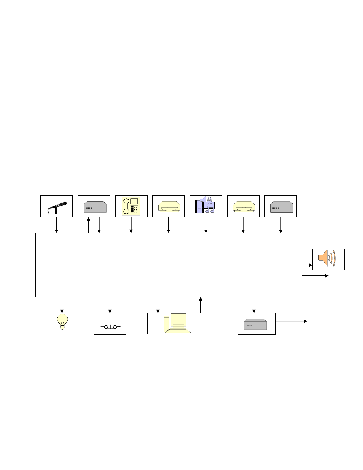
StudioDrive audio connections are made via the Audio Interface unit. The block diagram below shows a typical
installation. All connections, except the Mic input, use T-R-S (“stereo”) ¼” phone plugs.
MIC COMP / EQ TELE CD PLAYER D.A.T. MINIDISC AIR MONITOR
MONITOR
MIC IN MIC PROCESS TEL IN LINE 1 IN LINE 2 IN LINE 3 IN AIR MON
StudioDrive
All I/O connections via Audio Interface
unit except for Line 3 input.
MIC TALLY COUGH SW. RECORD OUT PC IN MIXMINUS OUT
WARNING LIGHTS COUGH SW. COMPUTER SOUND CARD TELE HYBRID
(SUPERELAY) (N.O.) (LINE IN / OUT) (IF USED)
MIC INPUT Input for professional microphone. XLR: Pin 1 = GND, Pin 2 = HI, Pin 3 = LO.
MIC PROCESS Insert point (unbalanced) for external mic processing equipment, e.g., limiter, EQ, etc.
TIP = Output from processor to mic chan. input, RING = mic preamp output to processor, S = GND.
Levels to / from mic processor should be -5 dBu. Note: JP1 in Audio Interface unit must be ON.
LINE 1 L+R Line input #1 is for an unbalanced stereo source @ -10 dBv (levels up to 0 dBv are OK).
TIP = LEFT, RING = RIGHT, SLEEVE = GROUND
MONITOR OUT
PROGRAM OUT
SYSTEM
TO
TRANSMITTER
TO TELCO LINE
Page 3

PAGE 3
The following line level inputs should be wired as follows: TIP = HI, RING = LO, SLEEVE = GND.
For unbalanced sources connect the RING and SLEEVE together.
LINE 2 LEFT Line input #2, left channel. Input sensitivity set by JP1.
LINE 2 RIGHT Line input #2, right channel. Input sensitivity set by JP2.
P.C. LEFT Input for PC soundcard playback, left channel. Input sensitivity set by JP3.
P.C. RIGHT Input for PC soundcard playback, right channel. Input sensitivity set by JP4.
AIR MON LEFT Input for Air monitor, left channel Input sensitivity set by JP8.
AIR MON RIGHT Input for Air monitor, right channel Input sensitivity set by JP9.
TEL Connect to POTS line to record caller audio. TIP = RED, RING = GREEN, SLEEVE N/C
Note: the telecoupler bridges the telephone line. A standard telephone should also be connected
to the line to seize (terminate) the line while recordings are made (for recording caller audio only).
Note: A telephone hybrid must be used if both the caller and host are to be recorded or broadcast,
e.g., for a “talk show”. In this case, the hybrid’s caller audio output may be fed to the TEL input.
MONI L+R Unbalanced output to studio monitor system. TIP = LEFT, RING = RIGHT, SLEEVE = GND.
MIX MINUS Unbalanced output to feed “send” input of hybrid, if used. TIP = HI, SLEEVE = GND.
The following balanced outputs should be wired as follows: TIP = HI, RING = LO, SLEEVE = GROUND.
For unbalanced loads, connect to TIP and SLEEVE ONLY. DO NOT SHORT RING TO GROUND!
PGM LEFT Main Program output, left channel, on-air feed. (0 VU = +4 dBu)
PGM RIGHT Main Program output, right channel, on-air feed. “
REC LEFT Record bus output, left channel, to input of PC soundcard. (Output level adjustable.)
REC RIGHT Record bus output, right channel, to input of PC soundcard. “
TALLY/COUGH Logic circuits for mic control and On The Air warning light control:
TALLY: Provides +12 volts between TIP and SLEEVE when Mic is on. Connect to Henry
` Engineering Superelay DC control inputs to activate warning lights when Mic is on.
COUGH: Connect an external N.C. switch or pushbutton between the RING and SLEEVE to
control Mic. Opening the circuit turn Mic off; closing circuit turns mic on.
Note: JP2 in Audio Interface unit must be ON to enable remote Mic on/off control.
2.3 RECORD OUTPUT LEVEL CALIBRATION
Plug the flat cable from the Audio Interface unit into the header on the StudioDrive chassis. Be sure that the RED
STRIPE on the cable is at the right end of the header,
After all audio connections have been made the system can be powered up. Calibration consists of adjusting the
StudioDrive RECORD OUTPUT level to match in input sensitivity of the PC soundcard.
Average vs. peak levels
All PC recording/editing software has some type of on-screen audio level meter. Some meters read average levels,
while others read peak levels. The purpose of the meter should be to show average perceived level, so that all
recordings will play back at a consistent perceived level. Unfortunately, some on-screen level meters actually read
absolute peak levels. While this is useful to prevent system overloads, peak-reading meters are of little use in
determining average perceived level. Check the manual for the software being used to determine what the onscreen meter indicates.
The best way to calibrate a PC soundcard recording system is to determine the maximum operating level (“clipping
point”) for the system, then establish 0-VU at 15 to 20 db below the clipping point. This will ensure adequate
headroom above 0-V U for distortion-free audio peaks. Note: StudioDrive’s clipping point is 20 dB above 0-VU.
To calibrate record levels, feed a test tone (about 400 Hz) into any StudioDrive line input. Carefully set the level so
that the amber “0-VU” LED is lit. (This produces exactly +4 dBu at the Program outputs.)
Now put the soundcard into the RECORD mode. Adjust StudioDrive’s REC CAL trimmers to produce the
appropriate level into the soundcard. The REC CAL trimmers are at the back of the StudioDrive PC board.
as viewed from the rear of the StudioDrive chassis.
Page 4

PAGE 4
2.4 MOUNTING STUDIODRIVE INTO THE PC
After proper operation is verified, StudioDrive can be installed in the PC case. For best performance, StudioDrive
should be installed at the top of the drive bay.
Disconnect the PC from AC power and remove the outside cover. Carefully unplug the ribbon cable from the main
StudioDrive chassis. Route the ribbon cable through any open slot in the PC chassis, preferably a slot that is close
to the top end of the PC chassis. Route the cable to the drive bay area of the PC,
cables and PC boards. (Do NOT bundle it with other data cables in the PC!)
Now slide the StudioDrive chassis into the drive bay. Re-connect the ribbon cable, then install two #4 screws on
each side to firmly secure the StudioDrive chassis to the PC frame. Replace the PC cover; installation is complete.
keeping it away from other data
3.0 OPERATION
StudioDrive operates like any other broadcast audio console. A description of controls is below:
MIC ON/OFF BUTTON Switches the Mic on or off. When the button is IN, mic is on. The Monitor is
normally muted when the mic is on, unless this feature has been defeated.
MIC ON LED Illuminates when Mic is on.
MIC LEVEL POT Mix level for Mic channel. The normal range is between -20 and -10 dB.
L1 / TEL BUTTON Selects either LINE source #1 (out) or the TEL coupler (in) for mix channel. If TEL
is selected, audio may be recorded from a phone line. Note that this feature is for
recording caller audio only. It is not for doing a “talk show” where both caller and
host are recorded or broadcast. A regular telephone must also be connected to
the phone line so the call can be initiated (or answered) and the line “held” while
caller audio is being recorded. The telephone should have a mute button so that
ambient noise is not picked up by the telephone handset while recording.
TEL ON LED Illuminates when TEL is selected with button above.
L1 / TEL LEVEL POT Mix level for L1 / Tel channel. The normal range is -20 to -10 dB.
L2 / L3 SELECT BUTTON Selects either LINE source #2 (out) or LINE source #3 (in) for mix channel.
If this button is IN, the L3 INPUT JACK is active.
L3 INPUT JACK Input jack for Line source #3: unbalanced, -10 dBv, stereo mini-jack.
L2/ L3 LEVEL POT Mix level for L2 / L3 channel. The normal range is -20 to -10 dB.
PC PLAY / RECORD BUTTON Selects PC-Monitor mode. When this button is out (PLAY), Monitor system will
monitor either Program bus or Air monitor signal, depending upon MONITOR
PGM/AIR button. If PC PLAY/RECORD button is in (RECORD), Monitor system
will monitor the output of the PC soundcard. This permits the operator to listen
“through” the soundcard, to hear the effects of mixing or editing on the PC.
PC LED Indicates PC-Monitor mode selected above. GREEN = PLAY, RED = RECORD.
PC LEVEL POT Mix level for PC soundcard output. The normal range is -10 to -20 dB.
Note: The soundcard output is mixed to the Program (on air) output only.
It is not mixed to the Record output.
When recording to the PC, this pot should be set to OFF (CCW).
Page 5

PAGE 5
MONITOR PGM/AIR BUTTON When the PC PLAY/REC button is out (PLAY) this button is active. It selects
either the Program bus audio or Air monitor audio for the Monitor system. If the
PC PLAY/REC button is in (REC), this function is overridden.
MONITOR LED Indicates Monitor audio selection: GREEN = PROGRAM, RED = AIR,
OFF = PC-REC function is engaged (soundcard output is fed to Monitor system.)
MONITOR LEVEL POT Controls level of Monitor system. (Monitor system mutes when Mic is on.)
PHONES LEVEL POT Controls level of Headphones.
PHONES JACK For stereo headphones. Use medium or high impedance headphones only.
VU METER LEDS Indicates Program output level. 0-VU = +4 dBu.
3.0 OPERATION
StudioDrive has two distinct modes of use: “On Air” for live broadcasting, and “Production” for recording and
editing on the PC.
When StudioDrive is used for live broadcasting, the Monitor system should be set to AIR, so the operator can
monitor the stations off-air signal. The PC PLAY/REC button should be out, and the MONITOR PGM/AIR button
should be in.
In this mode, ALL audio sources are mixed to the main Program output. Set the level pots so that most peaks
cause the amber 0-VU LED to flash. The VU meter LEDs are calibrated to match the averaging ballistics of a
standard VU meter. There is an additional 20 dB of headroom above 0-VU. Adjust the Headphone and Monitor
levels as needed. The Monitor system will mute when the Mic is on, if this feature is enabled.
When StudioDrive is used for recording or editing with the PC, the Monitor system should be set to PC-RECORD.
The PC PLAY/REC button should be in, to allow monitoring the output of the soundcard. In this mode, all audio
sources except the PC soundcard audio are mixed to the Record output. To prevent erroneous readings on the
StudioDrive VU meter, the PC level pot should be set to OFF (CCW). If the Record output levels have been
properly calibrated, the StudioDrive VU meter will indicate correct recording levels for the soundcard in use. Adjust
mix levels so that most peaks cause the amber 0-VU led to flash.
3.1 MIC PREAMP GAIN CALIBRATION
The gain of the mic preamp should be optimized for the microphone in use. The mic preamp gain is adjusted via a
small hole labeled MIC GAIN on the Audio Interface unit. To set mic preamp gain, turn the Mic channel on, and set
the Mic Level pot to -15 dB. Speak into the mic, and adjust the gain trimmer so that the amber 0-VU LED flashes
on most audio peaks.
4.0 SPECIFICATIONS
INPUTS
MIC Bal, 10K, gain adj. 40-60 dB FREQ RESP 0 – 20 kHz, +/- 0.25 dB
LINE 1 Unbal, stereo, 10K x 2, -10 dBv nom DISTORTION 0.01% THD or IM
LINE 2 Bal stereo, 10K x 2, 0 dBu / unbal, 5K x 2, -10 dBv NOISE, Pgm, Rec 85 dB below nom output
LINE 3 Unbal, stereo, 10K x 2, -10 dBv HEADROOM 20 dB
PC Bal stereo, 10K x 2, 0 dBu / unbal, 5K x 2, -10 dBv DYNAMIC RANGE 105 dB
TEL Bal, 5K, transformer isolated input for tel line VU METER CAL 0 VU = +4 dBu
AIR Bal stereo, 10K x 2, 0 dBu / unbal, 10K x 2, -10 dBv
OUTPUTS
PGM Bal, stereo, 600 ohm load, +4 dBu nom, +24 dBu max
REC Bal, stereo, 600 ohm load, +4 dBu nom, +24 dBu max
MIXMINUS Unbal, 2k ohm load, -2 dBu nom, +20 dBu max
MONITOR Unbal, 600 ohm load, 0 dBu nom, +20 dBu max
MIC PROC Unbal, -5 dBv I/O Rev A. 3/2004
AUDIO PERFORMANCE
Specifications subject to change without notice.
Page 6

1
2
3
4
5
+3
1516
0
1314
-5
1112
-10
910
RIGHT
+3
78
0
56
-5
34
-10
12
LEFT
-15VB
+15VB
-15VA
+15VA
470uF
C54
470uF
C53
470uF
C52
470uF
C51
LED1H
LED1G
LED1F
LED1E
LED1D
LED1C
LED1B
LED1A
NE5532
+15V
84
U12B
47, 1/4W
R93
47, 1/4W
R92
2.00K
R113
47, 1/4W
R97
7
1
7
REC_R+
.01uF
1N4004
D19
+
1N4004
+
TP3
D18
1N4004
D17
+
1N4004
+
D16
-15V
+15V
TP2
TP1
47uF
+
C45
47uF
C44
+
C43
HP GND
E8
LM2990
VR2
1
GND
E7
IN OUT
2 3
+
LM2937
VR1
2
GND
OUT
3
+
IN
1
1000uF
C58
1000uF
C57
-18V
+18V
CHASSIS GND
REC_R-
10K 40%
13
R80
2
REC CAL R
REC_L+
LED_GND
47, 1/4W
REC_L-
LM3916
U15
MODE LED 10
9 10
REF ADJ
LED9
11
LED8
12
LED7
13
LED6
14
LED5
15
LED4
16
LED3
17
LED2
18
LED9
11
LED8
12
LED7
13
LED6
14
LED5
15
LED4
16
LED3
17
LED2
18
40
39
38
37
36
35
34
33
32
31
30
29
28
27
26
25
24
23
LM3916
U14
LED_GND
LED_GND
REC_R+
REC_R-
REC_L+
REC_L-
MON_R
MON_L
PWRGND
PWRGND
MIXMINUS
PGM_R+
PGM_R-
PGM_L+
PGM_L-
AIR_R-
AIR_R+
8
REF OUT
7
RHI
6
SIG
5
RLO
4
V+
3
V-
2
LED1
1
MODE LED 10
9 10
REF ADJ
8
REF OUT
7
RHI
6
SIG
5
RLO
4
V+
3
V-
2
LED1
1
-18V
E4
.1uF
C40
+15VB
.1uF
C39
+15VB
PWR GND
C42
C41
47uF
47uF
1K
+
R103
4.99K
R107
1K
R105
NE5532
U13B
+15VB
84
5
+
7
-
-15VB
20.0K
6
R111
1N4004
10K 40%
13
R79
2
MON_R
D11
1N4004
56.2K
D9
R109
1K
R102
NE5532
U13A
+
4.99K
R106
1K
R104
+15VB
84
3
+
1
-
-15VB
20.0K
2
R110
1N4004
D10
56.2K
R108
1N4004
D8
MON_L
RNG (R)
E6
TIP (L)
E5
R98
2.00K
R112
REC CAL L
R41
47, 1/4W
R40
METER/R
METER/L
+
C3
E8, E5, E6
(WIRE TO J3)
PHONES
+
C11
MIXMINUS
PGM_R+
1
U10B
47, 1/4W
7
NE5532
U10A
1
1000uF
1000uF
47, 1/4W
R47
R123 33.2K
R122 33.2K
2.49K
R89
R39
47, 1/4W
22
21
20
AIR_L-
AIR_L+
19
18
17
16
15
14
13
12
11
10
9
8
7
6
5
4
3
2
1
J1
COMP_R-
COMP_R+
COMP_L-
COMP_L+
LINE2_R-
LINE2_R+
LINE2_L-
LINE2_L+
LINE_1_R
LINE_1_L
TALLY
TEL_IN
MIC_CON
MIC_IN
D D
+18V
47, 1/4W
PGM_R-
R38
10
9
8
7
6
5
4
-15V
+15V
MIC_IN
BOOTH_R
BOOTH_L
MON_MUTE
R87
47, 1/4W
PGM_L+
R37
3
2
1
J4
BUS_INPUT/R
BUS_INPUT/L
47, 1/4W
PGM_L-
R36
C C
1.00K
1.00K
NE5532
U12A
NE5532
U11B
NE5532
U11A
NE5532
+
649
R88
2.49K
649
R86
+
-
-15V
+15V
84
+
-
-15V
+15V
84
+
-
-15V
+15V
84
+
-
-15V
+15V
84
+
-
-15V
+15V
84
+
-
-15V
47, 1/4W
R43
47, 1/4W
R42
47uF
C7
5
6
C56 300pF
R101
R100
3
2
C55 300pF
R99 2.49K
5
6
C27 300pF
R95 1.00K
R94 1.00K
3
2
C28 300pF
R96 2.49K
.1uF
C4
5
6
J174
Q3
C17 20pF
R121 33.2K
3
2
J174
Q2
.1uF
+15V
C16 20pF
.1uF
-15V
R119 33.2K
TO VU METER CKTS
NE5532
+15VA
84
U9B
+
7
-
-15VA
NE5532
+15VA
84
U9A
+
1
-
-15VA
100K
R81
NE5532
+15V
84
U1B
+
7
-
-15V
NE5532
+15V
84
U8B
+
7
-
-15V
NE5532
+15V
U8A
84
+
1
-
-15V
NE5532
+15V
U7B
84
+
7
-
-15V
C6 300pF
NE5532
+15V
U7A
84
+
1
-
-15V
C5 300pF
of
11Thursday, January 08, 2004
1
503 Key Vista Drive
Sierra Madre, CA 91024 USA
telephone - (626) 355-3656
5000 B
FAX (626) 355-0077
HENRY ENGINEERING
NOTE: UNLESS OTHERWISE SPECIFIED
1. ALL RESISTORS ARE 1/8W, 1%.
SCHEMATIC: RADIO DRIVE
C
Title
Size Document Number Rev
Date: Sheet
R78 4.99K
R77 4.99K
R76 4.99K
R75 4.99K
R67 4.99K
R68 4.99K
R69 4.99K
R70 4.99K
LO
HI
R13 4.99K
R12 4.99K
LINE 2 R
R11 4.99K
R10 4.99K
2.49K
R120
COMP R
LINE 2 L
LED_GND
TALLY
AIR_R-
AIR_R+
AIR_L-
AIR_L+
COMP_R-
COMP_R+
COMP_L-
COMP_L+
COMP L
LINE2_R-
LINE2_R+
LINE2_L-
LINE2_L+
LINE_1_R
TEL_IN
LINE_1_L
S1=MIC OFF/ON
MIC_CON
+15VB
MIC_IN
2
3
4
5
TEL ON=RED
RED
D3
R25 2.49K
1 2
10
11
12
S2D
+15VB
R83
2.49K
MON AIR=RED
3
GRN
1
D6
MON PGM=GRN
10
12
2
S5D
2.49K
R31
2
11
RED RED
3
GRN
1
D4
COMP REC=RED
10
11
12
S4D
COMP PLAY=GRN
47, 1/4W
R118
R29 10K
100K
R28
51
R27 10.0K
6
R24B
10K, 18%
42
R26 10.0K
3
10K, 18%
R24A
C38
C37
5
6
100K
R82
3
2
10.0K
R33
10.0K
R32
R24=MON LEV
10K, 18%
51
R30B
6
R30=PH LEV
42
10K, 18%
R30A
3
5
6
R58 33.2K
R115 33.2K
C15 20pF
R44 332K
R114 33.2K
R46 33.2K
R90 33.2K
R45 33.2K
5
6
.1uF
C36
+15V
C14 300pF
.1uF
C35
-15V
R55 1.00K
R56 1.00K
R85 2.00K
3
2
R52 2.00K
C13 300pF
R54 2.49K
5
6
10.0K
47uF
C8
NE5532
U5A
1
+15V
-15V
R91
R1 10.0K
84
+
-
C9 20pF
B B
R49 1.00K
R57 1.00K
2.00K
R84
3
2
R48 2.49K
+15V
-15V
2.00K
.1uF
.1uF
R51
+
C34
C33
MON_MUTE
123
ON
4
5
6
S4C
REC
7
8
9
S4B
1
2
3
S4A
REC
NE5532
U6B
7
123
JP5
JP7
OFF
MON MUTE
5
S5C
COMP
3
2
1
JP9
4
6
S4=COMP PLAY/RECS5=MON PGM/AIR
7
8
9
S5B
1
2
3
S5A
123
COMP
JP6
10K, 18%
51
+15V
-15V
84
5
+
6
-
R20B
6
R23 10.0K
LO
AIR R
HI
NE5532
+15V
U4B
47uF
+
7
C26
-15V
3.32K
R74
LO
3
2
1
AIR L
HI
JP8
NE5532
+15V
U4A
47uF
+
1
C25
-15V
3.32K
R117
NE5532
+15V
U3B
47uF
+
7
C24
-15V
3.32K
R63
C49 20pF
R72 56.2K
NE5532
+
U6A
+15V
84
47uF
C47
1
47uF
C48
+
+
-
-15V
R71 56.2K
R17 10.0K
R16 10.0K
3
2
C50 20pF
51
6
10K, 18%
R14B
+
R14=LINE 2 LEV
42
3
10K, 18%
R14A
+
47uF
C22
C21 47uF
10K, 18%
R20A
3
R22 10.0K
E1, E2, E3
(WIRE TO J2)
LINE 3 IN
11
S3D
5
S3C
8
S3B
2
S3A
42
GND
E3
TIP (L)
E2
RNG (R)
E1
10
12
4
6
7
9
1
3
S3=LINE 2/3 SEL
R35 10.0K
U3A
47uF
+
C23
R20=COMP LEV
U2B
U2A
1
7
3.32K
1
NE5532
+15V
-15V
3.32K
NE5532
+15V
-15V
R60
NE5532
+15V
-15V
10.0K
3.32K
R9 10.0K
NE5532
U5B
+15V
47uF
+
C10
84
5
+
7
-15V
6
-
3
10K, 18%
R3A
42
C12 20pF
R53 56.2K
.1uF
+15V
10.0K
R34
51
42
10.0K
R6
6
3
10K, 18%
R5A
3
2
+15V
-15V
.1uF
.1uF
C30
C29
.1uF
-15V
R5=MIC LEV
10K, 18%
R5B
NE5532
U1A
+15V
+
1
C18 47uF
-15V
6
R3=LINE 1/TEL LEV
C32
C31
+15V
84
3
+
2
-
C1 20pF
R4 10.0K
51
10K, 18%
R3B
R8 10K
100K
R7
Q1
J174
+15V
C2
+
C20 47uF
+
C19 47uF
.1uF
R2 10.0K
84
+
-
84
+
-
84
+
-
R18 10.0K
84
+
-
R66 10.0K
R64
84
+
-
R62 10.0K
84
+
-
R59
5
6
3
2
5
6
3
2
1
3.32K
R65
3
2
5
6
3
2
1
R15
3
2
3
R116
2
1
5
8
S2B
2
S2A
10
12
4
6
7
9
1
3
MIC ON IND
3.32K
S2C
S1D
S1C
S1B
S1A
R73 3.32K
R21 3.32K
R19 3.32K
LO
HI
JP4
3
2
1
JP3
R61 3.32K
LO
HI
JP2
LO
HI
JP1
4
6
7
9
1
3
S2=LINE 1/TEL SELECT
11
5
8
2
1 2
D1
RED
R50 56.2K
A A
Page 7

TEL IN
PROCESS
INSERT
of
J15
NJ3FD-V
1
JP1
INSERT
ON
OFF
3
2
1
OFF
13
2
VR1 100
C3 .33uF
T2
42TM018
2
1
3
14
26
CW
D1
1N4004
D2
2
1N4004
C4
+15V
.1uF
U1
R2
47 5%
C8
SSM-2019
1
7
213
6
+
3
J17
NJ3FD-V
+
47uF 25V
-
2
R4
8
5
4
503 Key Vista Drive
Sierra Madre, CA 91024 USA
telephone - (626) 355-3656
1. ALL RESISTORS ARE 1/4W, 1%.
NOTE: UNLESS OTHERWISE SPECIFIED
FAX (626) 355-0077
HENRY ENGINEERING
2 3
1
IN OUT
-15V
TP3
GND
SCHEMATIC: I/O BOX
Title
1
10
C11
.1uF
-15V
+15V
TP2
Q1 LM7812
1
OUT
IN
3
GND
TP1
2
1
Q2 LM7912
1
11Thursday, January 08, 2004
1
5050 B
B
Size Document Number Rev
Date: Sheet
2
1N4004
D3
11
3
+
C1
1N4004
D5
E6
230V
E4
1000uF
121413
564
C7
200pF
+18V
1N4002
1N4002
10.0K
C6
.001uF
D10
D9
R3
1N4002
1N4002
10.0K
C9
+
47uF 63V
C10
.001uF
D8
D7
R1
3
C5
+
47uF 63V
C2
1N4004
D4
115V
115V
E3
+
E5
1000uF
D6 1N4004
T1
X70032
-18V
3
F1
250mA
1
2
MIC
PREAMP
J10
NJ3FD-V
3
NC3FAV
COMP IN L
J11
NJ3FD-V
COMP IN R
J12
NJ3FD-V
AIR IN L
AIR IN R
J13
NJ3FD-V
J16
4
MIC TALLY/
COUGH
SW.
J14
NJ3FD-V
LINE 1 IN
J7
NJ3FD-V
LINE 2 IN L
J8
NJ3FD-V
LINE 2 IN R
J9
NJ3FD-V
BLK
E2
PGM OUT L
J1
NJ3FD-V
J2
AC
PGM OUT R
NJ3FD-V
WHT
E1
INPUT
MIXMINUS OUT
J4
NJ3FD-V
J3
MONITOR OUT
NJ3FD-V
REC OUT L
J5
NJ3FD-V
REC OUT R
J6
NJ3FD-V
4
GND RTN
213
213
213
213
213
213
213
213
2
1
3
213
213
2
1
3
2
1
3
213
COUGH SW
JP2
5
ON
OFF
3
2
1
J18
MIC
1
MIC_CON
TEL_IN
2
3
D D
TALLY
4
LINE_1_R
LINE_1_L
5
6
LINE2_L+
7
8
LINE2_L-
9
10
LINE2_R-
LINE2_R+
11
12
E7
+18V
AIR_L-
COMP_L+
COMP_L-
13
14
C C
COMP_R+
COMP_R-
15
16
17
AIR_L+
18
19
20
21
22
AIR_R-
AIR_R+
23
-18V
PWR GND
33
REC_L-
MON_R
34
PGM_L-
24
25
26
27
28
29
30
B B
MON_L
31
32
MIXMINUS
PGM_R+
PGM_R-
PGM_L+
35
REC_R-
REC_L+
36
37
REC_R+
38
A A
39
40
5
 Loading...