

Page 1

HENRY ENGINEERING
STEREO AUDIO MONITOR
DIGITAL AND ANALOG STEREO LEVEL AND PHASE METER
DESCRIPTION
The Stereo Audio Monitor (SAM) is a stereo level and phase meter that incorporates Single Stereo Displ ay*
technology. SAM provides a visual indication of the levels and phase relationships of a stereo audio signal. A large
arc of 17 LEDs indicates Left and Right channel levels; a horizontal row of 10 LEDs displays the Sum and
Difference components of the stereo signal. SAM’s dual tri-colored Single Stereo Displays show this information in
an intuitive and easy-to-comprehend format. Both analog and AES/EBU digital signals can be monitored with SAM.
TM
503 Key Vista Drive
Sierra Madre, CA 91024
Tel: 626.355.3656
Fax: 626.355.0077
www.henryeng.com
WARNING! For 230V operation, change mains voltage jumpers before connecting to AC power!
Remove jumpers between E6 & E9, and between E7 & E8. Install a jumper between E6 & E7 for 230V; replace
fuse with .125a fuse. See schematic on reverse side. Jumpers should be changed by a qual ified technician only.
INSTALLATION
To monitor a stereo analog audio, connect to the left and right input. To monitor digital audio, connect to either of
the AES/EBU inputs. Wire the XLRs with Pin 2 HI, Pin 3 LO, and Pin 1 Ground. The XLR digital input is for AES3
signals (110 ohm termination); the BNC input is for AES3id signals (75 ohm termination). NOTE: SAM is shipped
from the factory with termination set to 110 ohms. If the BNC input is used, the termination should be changed to
75 ohms. Open the unit, and set JP1 to its alternate position. JP1 is located near the digital input XLR connector.
CALIBRATION
The Left, Right, Sum and Difference displays have independent calibration trimmers. SAM is set at the factory so
that an analog input of +4 dBu corresponds to “0-VU”, but it can be recalibrated over a wide range of input levels.
To calibrate the Level display, feed a tone at the desired 0-VU level into the Left input. Adjust the Left (L) trimmer
so the green 0-VU LED is lit. Then feed tone into the Right input, and set the Right (R) trimmer so the red 0-VU is
lit. Now feed tone into both channels; the LEDs will be yellow.
With tone feeding both the Left and Right inputs, adjust the Sum (S) trimmer for a green 0-VU reading on the Phase
display. To calibrate the Difference display, it is necessary to reverse the polarity of one input to SAM. With both
channels fed at the same level but opposite polarity, adjust the Difference (D) trimmer for a red 0-VU reading.
The calibration procedure is identical when using the digital input. (The factory setting is 0-VU = -20 dBfs.)
USER SETTINGS
On the back of the unit there are two pushbuttons, labeled IN and PH. The INput button selects either the Analog
(out) or the Digital (in) input. The Phase button selects the response time for the Phase displ ay, either Slow (out) or
Fast (in). (The Phase display will more effectively show high-frequency phase information if it is set to Fast.)
NOTE: We goofed! The silkscreened labels for these two buttons were inadvertently reversed! The PH button is
actually on the LEFT, and the IN button is on the RIGHT.
OPERATION
SAM consists of two independent LED displays. The main Single Stereo Display arc of 17 tri-color LEDs provides
an accurate indication of stereo audio levels over a range of -25 to +3 VU. The LEDs show the Left channel in
green and the Right channel in red. When both channels are present, the LEDs will be yellow. By watching the
Single Stereo Display, an observer can easily read the levels of both audio channels, see the balance between the
channels, and instantly see if a channel is missing. In addition, a blue “Peak” LED indicates a udio peaks that
exceed 0-VU. Extensive field testing has determined that, after a short adaptation period, an observer can quickly
see more useful information from SAMs Single Stereo Display than from watching a pair of traditional VU meters.
The ballistics of the display conform to industry standard VU meters, and show the perceived loudness of most
program material with reasonable accuracy.
Below the Level display is the tri-color Phase display, an array of 10 LEDs. These indicate the levels of the Sum
(L+R) and Difference (L-R) components of the stereo signal. The Sum is shown in green, with the Difference shown
in red. These colors will accurately indicate the relative levels of the Main (baseband) and Stereo Subcarrier
components of an FM or TV broadcast signal. With typical stereo program material, the display will appear mostly
green, with yellow or red indicating the amplitude of L-R content. High yellow levels would indicate excessive L-R
content or phase errors (which can exasorbate multipath and reduce loudness), and a redph ase display would
indicate a polarity reversal in the audio system. In most cases, the LED Phase display is easier to read and
interpret than a lissajous pattern on a vectorscope, especially for non-technical personnel.
Page 2
PAGE 2
PHONES JACK
SAM includes a Headphone jack on the front panel. It may be used for aural monitoring. Use contemporary
headphones with an impedance of at least 24 ohms. Do not use older “8 ohm” headpho nes.
DISABLING THE PHASE DISPLAY
The Phase display can be turned off if it is unnecessary or confusing to non-technical personn el. Open the unit,
and set JP2 to OFF. JP2 is located just behind the row of Phase display LEDs.
TECHNICAL SPECIFICATIONS
Analog Inputs 20K imped, balanced, stereo
Digital Input, XLR* AES3 (AES/EBU), 110 ohms
Digital Input, BNC* AES3id, 75 ohms
Digital Input sample rate 32 kHz to 192 kHz
Input Level range, analog 0 VU = -4 dBu to +10 dBu
Input Level range, digital 0 VU = -26 dBfs to -14 dBfs
Level display -25 to +3 VU
Phase display -23 to 0 VU
Monitor output 3.5mm jack for stereo headphones, 24 ohms min.
Power Requirement 115 or 230 VAC, 50-60 Hz, 6W
Construction Steel enclosure
Physical 5.75”w X 5.50”d X 1.60”h, 3 lbs
Approval City of Los Angeles Elect. Test Lab
*Requires optional AES decoder.
Specifications subject to change without notice.
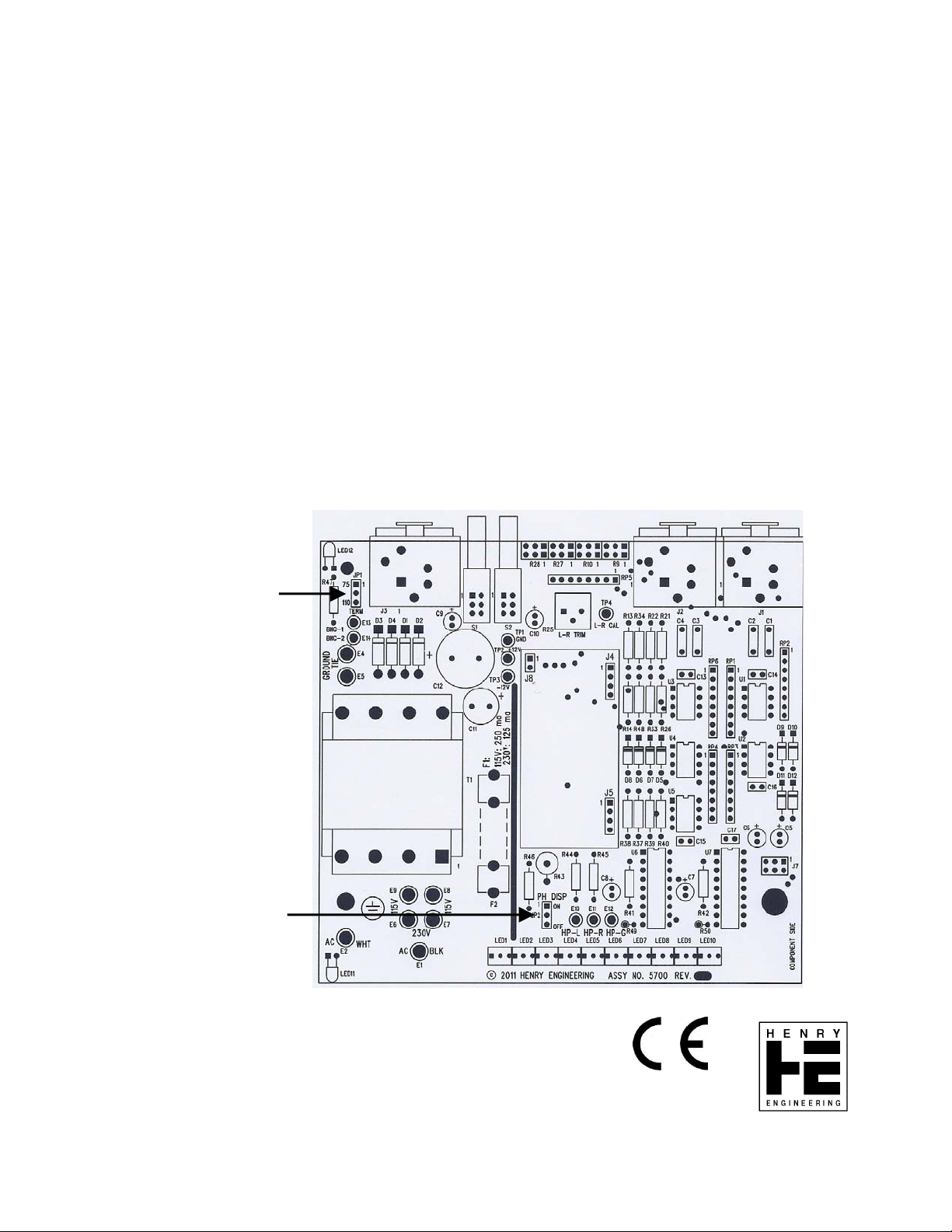
JP1 - TERMINATION JUMPER
JP2 – PHASE DISPLAY ON/OFF
Rev. A 05/11
 Loading...