

Page 1

TM
POWERSWITCH
FAILSAFE AC POWER CONTROLLER
DESCRIPTION
PowerSwitch is an automatic AC power controller. It can be used to switch AC power between Main and Backup
devices, or to simply turn AC power on or off. PowerSwitch can be operated using the front panel pushbuttons or
remotely controlled via external GPI contact closures. An audible alarm and remote status indication is provided.
INSTALLATION
HENRY ENGINEERING
503 Key Vista Drive
Sierra Madre, CA 91024
Tel: 626.355.3656
Fax: 626.355.0077
www.henryeng.com
WARNING! For 230V operation, change mains voltage jumpers before connecting to AC power!
Remove jumpers between E5 & E8, and between E6 & E7. Install a jumper between E5 & E6 for 230V; replace
fuse with .125a fuse. See schematic on reverse side. Jumpers should be changed by a qualified technician only.
Control and Status circuits for PowerSwitch are via a plug-in euroblock connector. Remove about 1/8” of insulation,
insert the wires into the plug, and tighten the screws. Be certain that no bare wires are exposed.
CONTROL INPUTS
PowerSwitch can be switched between the Main and Backup modes via external GPI contact closures at the
CONTROL connector on the rear of the unit. There are two control inputs: M (Main) and B (Backup), plus a G
(ground) terminal. A closure (switch, relay, open collector) between the M and G will set the unit to Main mode; a
closure between B and G will set the unit to Backup mode. Closures can be either momentary or maintained.
NOTE: A maintained
switch the unit to Backup mode, and removing that closure will cause the unit to automatically return to Main mode.
NOTE: A maintained
If PowerSwitch is being used to control Arbitron PPM™* Encoders, connect a pair of wires from the PowerSwitch
B and G Control terminals to pins 2 and 3 of the “Alarm Connection” connector (DB-9) on the PPM™ Monitor. If the
PPM™ Monitor senses an encoding fault, it will command the PowerSwitch to activate the backup Encoding unit.
STATUS RELAY
Dry contacts from an internal SPDT relay indicate mode of the unit. When PowerSwitch is in Main mode, there is
continuity between the NC and C terminals. When in Backup mode, there is continuity between the NO and C
terminals. These relay contacts are rated for 24 volts @ 1 amp. An internal jumper can be set so that PowerSwitch
supplies 12 volts DC on the Status relay outputs. To enable, open the unit and set the RELAY DC jumper (JP1) to
the ON position. 12 VDC will appear at either the NC or NO terminal, depending upon the mode of the unit.
AC OUTLETS
There are two 3-prong grounded outlets for the equipment being controlled. The MAIN outlet is live when
PowerSwitch is in Main mode; the BACKUP outlet is live when in Backup mode. (Both outlets are never live at the
same time.) Each outlet can supply up to 500 watts of AC power.
OPERATION
PowerSwitch can be controlled using either the front panel buttons or via inputs at the Control connector.
PowerSwitch always powers-up in Main mode. The Main outlet will be live, with the Backup outlet off. Switching to
Backup model causes the Backup outlet to become live, with the Main outlet turning off. PowerSwitch will stay
“latched” in Backup mode until it is reset with the front panel button or with a contact closure at the M Control input.
When PowerSwitch switches to Backup mode, an audible alarm will sound to alert nearby personnel that backup
equipment has been activated. The alarm can be turned off with a front panel switch. LEDs indicate Main and
Backup modes.
SPECIFICATIONS
AC input 115 VAC, 2 W + load wattage
AC outputs 2: Main and Backup, 115 VAC, 500 W per outlet
Control inputs 2: Main and Backup, maintained or momentary GPI closures
Status output SPDT relay, dry contacts or 12VDC from internal power supply
Alarm Audible alarm sounds when in Backup mode
Physical 5.75”w X 5.50”d X 1.60”h, 3 LBS
Construction Steel enclosure
Approval City of Los Angeles Electrical Test Lab
Specifications subject to change without notice. Rev. 02/09
*Arbitron PPM™ and PPM™ are trademarks of Arbitron Inc. Used with permission.
closure between M and G will allow “auto-return” operation: a closure between B and G will
closure between B and G will prohibit the unit from switching to Main mode.
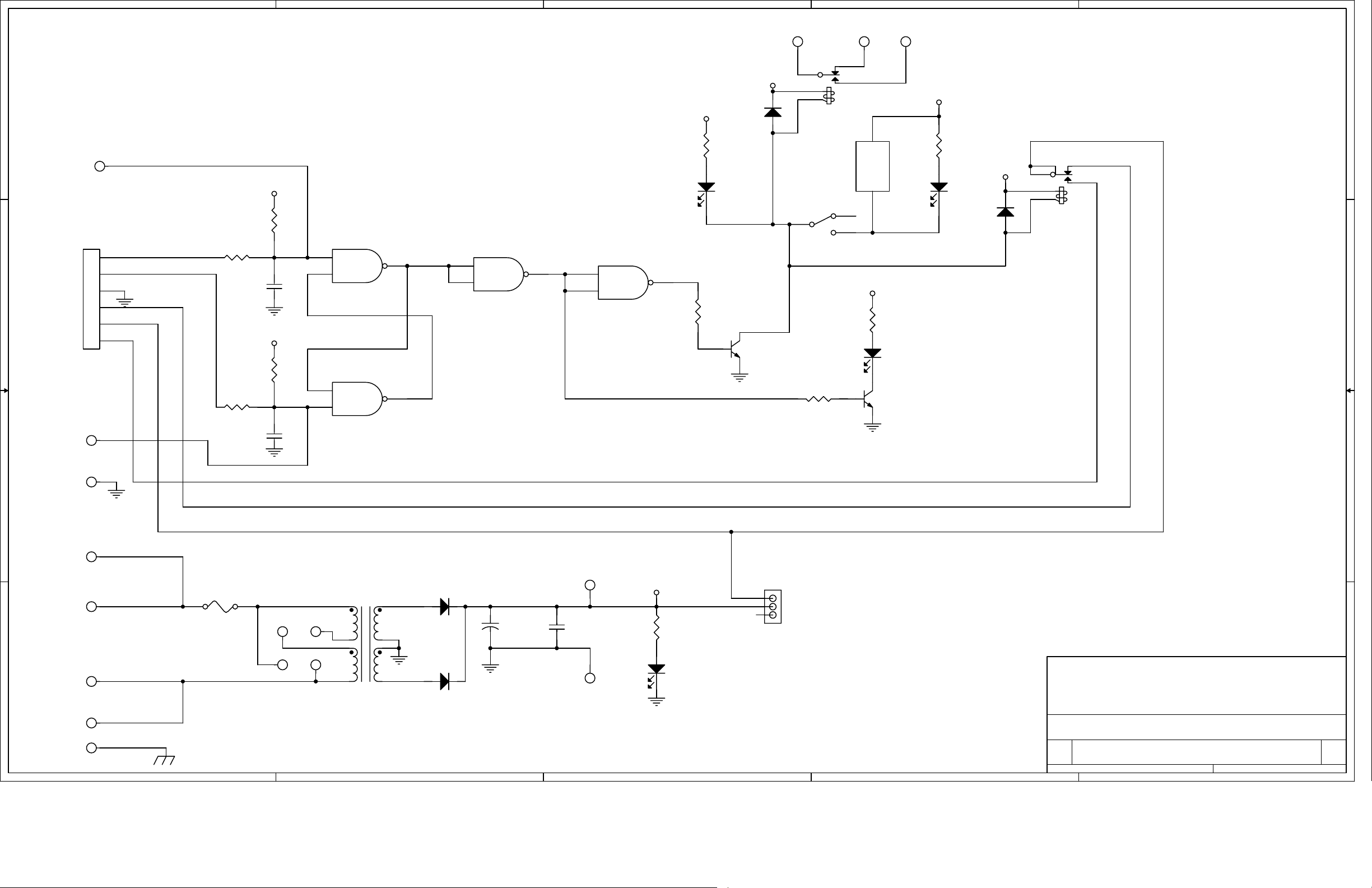
Page 2
5
4
3
2
1
MAIN-AFUSE-TIP BACKUP-B
E10 E9
4
+12V
D D
+12V
D3
1N4004
R8
E12
1.5K
B
+12V
B
LED3
1
2
3
RLY1
BZ1
ALARM
5
12
+-
SW1
R1
10K
J1
B
2
A
1
C C
GND
COM
NC
NO
3
4
5
6
R4 100
C3
.1uF 50V
+12V
R2
100K
R3 100
E13
A
C4
.1uF 50V
U1A
CD4011BCN
2
1
U1B
CD4011BCN
5
6
U1C
CD4011BCN
3
8
9
10
CD4011BCN
12
13
U1D
11
R6
10K
Q1
2N4401
4
2
ALARM
R7
10K
1
3
+12V
A
Q2
R10
1.5K
LED2
2N4401
E11
+12V
R9
1.5K
LED4
ALARM
1N4004
D4
+12V
6
1
2
5
RLY2
4
3
E14
B B
A A
GND
FUSE-SIDE
AC INPUT
NEUTRAL
E3
E1
E2
E4
M1
BLK/BRN
WHT/BLUE
GRN
5
F1
115V: 250 ma; 230V: 125ma
230V
E6
115V
E7
E5
E8
SPW-102
1
2
3
4
T1
TP2
ON
+12V
R11
1.5K
LED1
3
ON
2
1
OFF
JP1
RELAY DC
Title
D1
5
SECPRI
1N4004
6
7
+
1000uF 25V
C1
1
C2
.1uF 50V
1
D2
8
1N4004
TP1
NOTE: UNLESS OTHERWISE SPECIFIED
1. ALL RESISTORS ARE 1/4W, 5%.
HENRY ENGINEERING
503 Key Vista Drive
Sierra Madre, CA 91024 USA
telephone - (626) 355-3656
FAX (626) 355-0077
SCHEMATIC: AC SWITCHER
Size Document Number Rev
B
5600 B
4
3
2
Date: Sheet
1
of
11Monday, December 29, 2008
 Loading...