

Page 1

PATCHBOX II
HENRY ENGINEERING
STEREO OUTPUT MULTIPLIER
Sierra Madre, CA 91024
Tel: 626-355-3656
Fax: 626-355-0077
DESCRIPTION
PatchBox is a passive “output multiplier” that can be used to distribute the output of a professional audio mixer
to the inputs of peripheral equipment. PatchBox is ideal for feeding a mixer’s output signal into DAT recorders,
digital editors, computer sound cards, cassette and reel decks, VCRs, PA systems, dubbing racks, limiters, and
other audio equipment. Both professional equipment with balanced inputs and consumer equipment with
unbalanced inputs can be used.
PatchBox is compatible with any active balanced (transformerless) low impedance signal source that is groundreferenced. (Most professional mixers built since the early 1980s use this topology.) From a stereo source,
PatchBox creates twelve stereo outputs: six balanced stereo outputs and six unbalanced stereo outputs.
PatchBox balanced outputs, on XLR and TRS connectors, provide a “unity gain” signal with a 600 ohm source
impedance. PatchBox unbalanced outputs, on gold-plated “RCA” connectors, provide a signal that is compatible
with the inputs of consumer gear. Because the inputs circuits of audio equipment are normally high-impedance
(“bridging”), any combination of outputs can be used simultaneously without interaction or signal degradation.
INSTALLATION
A balanced, LO-Z audio source should be connected to the PatchBox BALANCED INPUT TRS connectors.
Wire the input plug as follows: Tip = HI; Ring = LO; Sleeve = GROUND. The input signal must be from a lowimpedance source that is ground-referenced, e.g., a transformerless active balanced output.
PatchBox balanced outputs should be wired as follows:
XLR OUTPUTS: Pin 1 = GROUND; Pin 2 = HI; Pin 3 = LO
TRS OUTPUTS: Tip = HI; Ring = LO; Sleeve = GROUND
Patchbox unbalanced outputs should be wired conventionally. Unbalanced cables should not exceed 20 feet.
OPERATION
PatchBox has no adjustments or user controls. The balanced outputs will be at the same level as the source
signal; unbalanced outputs will be about 10db below the source signal. NOTE: If PatchBox is used with an
audio source that is not ground-referenced (a transformer-coupled output which is isolated from ground), the
PatchBox unbalanced outputs will not operate.
TECHNICAL SPECIFICATIONS
Inputs: Left and Right on TRS connectors
Balanced, low impedance, ground referenced
Any professional level, +4 dBu typical
Balanced Outputs: Level: Unity gain
Load: 3K ohms or higher
2 stereo pairs on XLR connectors
4 stereo pairs on TRS connectors
Unbalanced Outputs: Level: 10 db below input level
Load: 10K ohms or higher
6 stereo pairs on RCA connectors
Freq. response: DC to 50 kHz
Noise, distortion None
Physical: 6.0”w x 3.5”h x 2.5”d 2 lbs.
Construction Aluminum enclosure and front panel
Technical specifications subject to change without notice.
503 Key Vista Drive
Page 2
5
4
3
2
1
D D
C C
LEFT INPUT LEFT BAL OUTPUTS
J1
NJ3FD-V
2
1
3
RP2A 330
1 2
RP2B 330
RP2C 330
RP2D 330
RP2E 330
RP1A 330
1 2
RP1B 330
31
RP1C 330
41
RP1D 330
51
RP1E 330
61
3
2
1
31
41
51
61
3
2
1
2
1
3
2
1
3
2
1
3
P1
NC3MAV
P3
NC3MAV
J3
NJ3FD-V
J5
NJ3FD-V
J7
NJ3FD-V
J2
NJ3FD-V
RIGHT BAL OUTPUTSRIGHT INPUT
RP4A 330
2
1
3
RP5A 330
1 2
RP5B 330
RP5C 330
RP5D 330
RP5E 330
1 2
RP4B 330
31
RP4C 330
41
RP4D 330
51
RP4E 330
61
3
2
1
31
41
51
61
3
2
1
2
1
3
2
1
3
2
1
3
P2
NC3MAV
P4
NC3MAV
J4
NJ3FD-V
J6
NJ3FD-V
J8
NJ3FD-V
RP1F 330
RP2F 330
71
B B
71
2
1
3
J9
NJ3FD-V
RP5F 330
RP4F 330
71
71
2
1
3
J10
NJ3FD-V
E1
GND
LEFT UNBAL OUTPUTS RIGHT UNBAL OUTPUTS
RP3A 3.9K
1 2
RP3B 3.9K
RP3C 3.9K
RP3D 3.9K
RP3E 3.9K
J11A
2 1
31
41
51
61
J11B
5 4
J12A
2 1
J12B
5 4
J13A
2 1
RP6A 3.9K
1 2
RP6B 3.9K
RP6C 3.9K
RP6D 3.9K
RP6E 3.9K
J11C
3 1
J11D
31
41
51
61
6 4
J12C
3 1
J12D
6 4
J13C
3 1
HENRY ENGINEERING
A A
5
RP3F 3.9K
71
J13B
5 4
RP6F 3.9K
4
3
71
J13D
6 4
Title
Size Document Number Rev
2
Date: Sheet
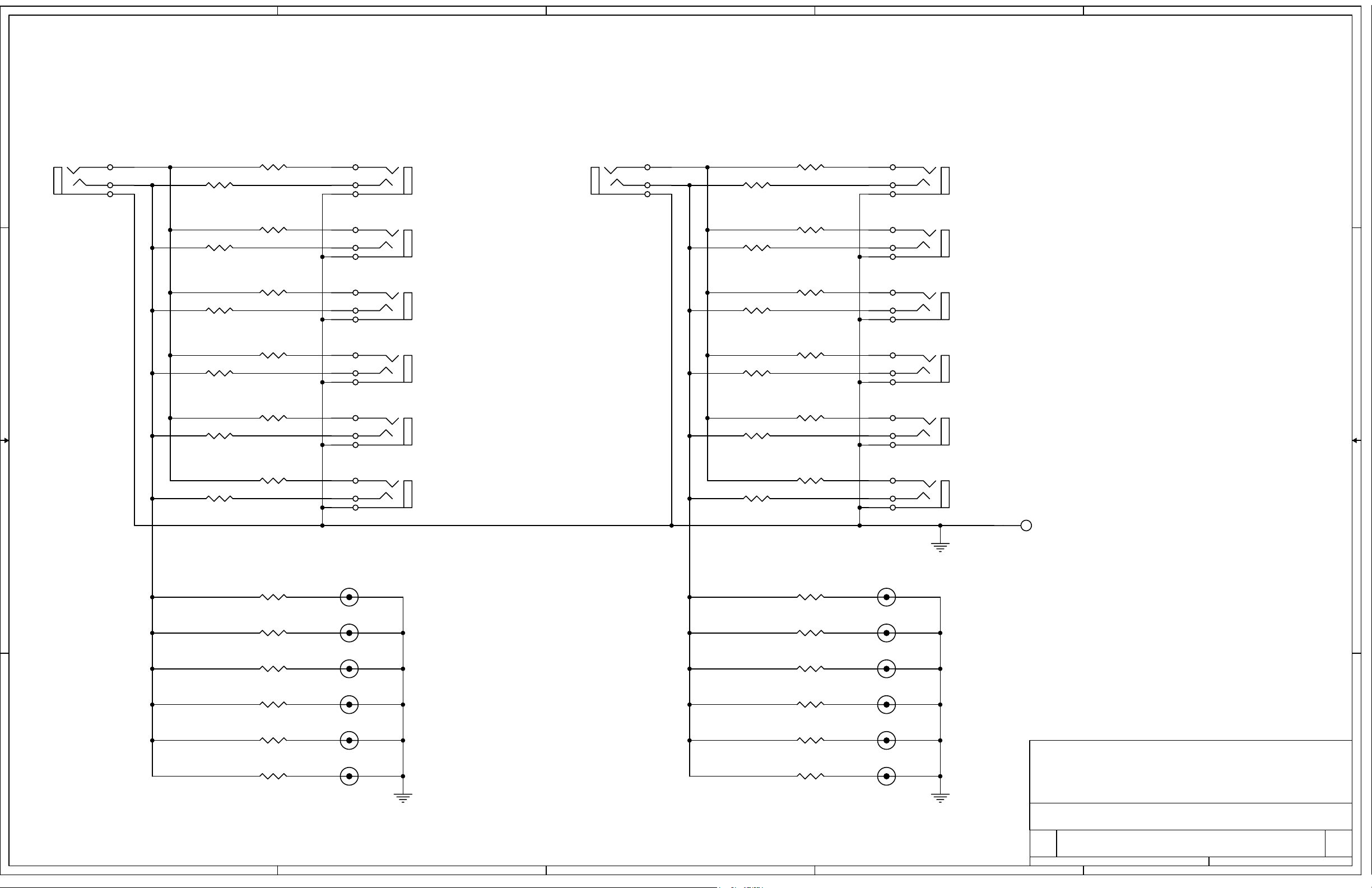
SCHEMATIC: PATCHBOX II
B
2150 A
503 Key Vista Drive
Sierra Madre, CA 91024 USA
telephone - (626) 355-3656
FAX (626) 355-0077
1
11Wednesday, July 28, 2004
of
 Loading...