

Page 1
g
HENRY ENGINEERING
TM
MULTIPORT
Multi-Format Audio Interface Panel
DESCRIPTION
The MultiPort panel is a utility interconnect device that facilitates interface between a studio or professional audio system
and external audio devices. MultiPort provides convenient access to system audio inputs and outputs, and allows
connection to digital and analog equipment at both professional and consumer signal levels. Digital I/O can be via either
the AES/EBU or S/PDIF standard. Balanced audio outputs are provided at +4dBu and -50dBu and also unbalanced at
-10 dBv. MultiPort can accept analog inputs at +4dBu (balanced) or -10 dBv (unbalanced). XLR, ¼” TRS, 3.5mm Mini
TRS, and RCA jacks are provided for interface. MultiPort is powered by an external AC power transformer, included.
INSTALLATION
MultiPort can be mounted in a rectangular cutout in studio cabinetry. The cutout should be 11” W x 2 1/2” H. (A rack-mount kit is
optionally available, for mounting MultiPort in a 2RU rack opening.) Audio and power connections to MultiPort are via three “euroblock”
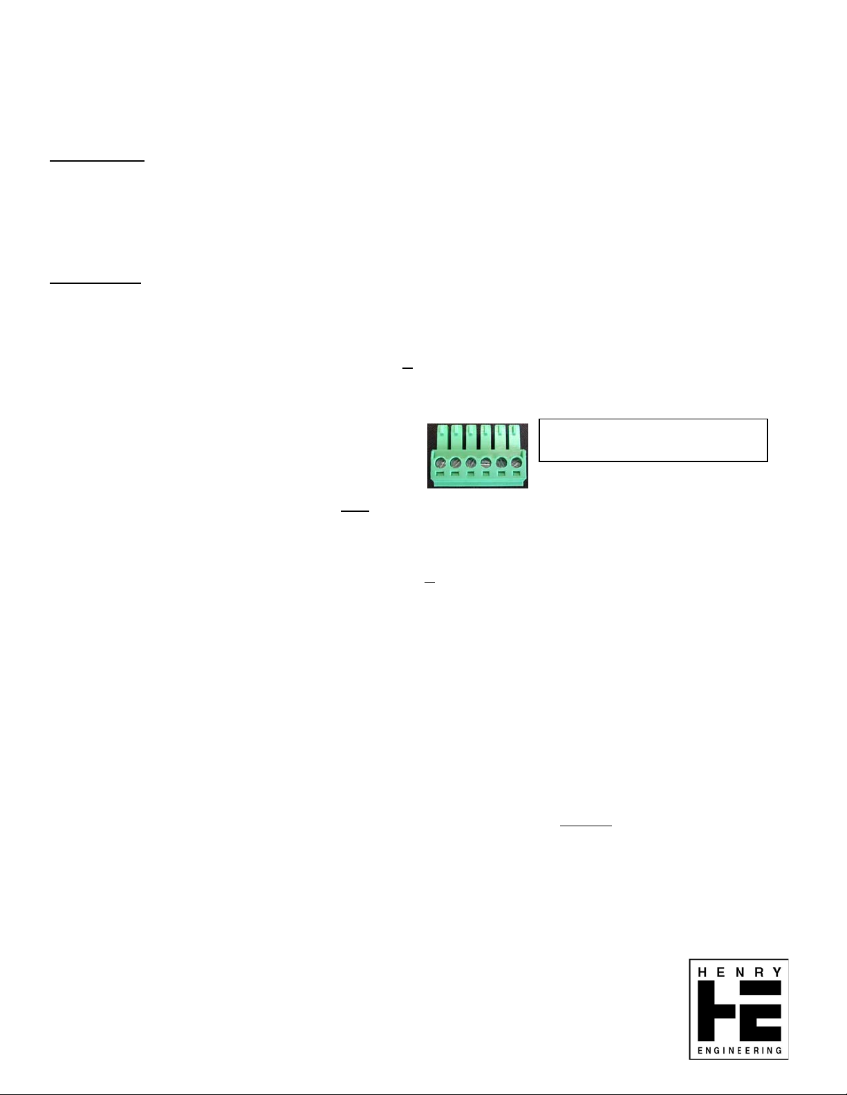
connectors on the PC board, labeled “To Studio”, “From Studio” and “AES,PWR”. Wire the mating plugs according to the information
below. Note that the pins are numbered left-to-right, with the screws facing up.
503 Key Vista Drive
Sierra Madre, CA 91024
Tel: 626-355-3656
Web: www.henryeng.com
TO STUDIO: This connector sends analog audio from MultiPort to
All analog wiring to/from MultiPort should be balanced, lo-z, at professional +4 dBu levels.
PIN 1 LEFT +
PIN 2 LEFT –
PIN 3 GROUND
PIN 4 RIGHT +
PIN 5 RIGHT –
PIN 6 GROUND
FROM STUDIO: This connector sends analog audio from
Pin assignments are identical to those shown above.
AES, PWR: This connector is for the AES digital input and output, and also the power input to MultiPort:
PIN 1 AES + OUTPUT AES digital audio output of MULTIPORT to
PIN 2 AES – OUTPUT
PIN 3 AES+ INPUT Studio AES output (e.g., output of digital D.A.) to MULTIPORT digital output connectors
PIN 4 AES – INPUT
PIN 5 POWER INPUT 12V AC input to MULTIPORT (This is also the ground of MULTIPORT internal circuitry.)
PIN 6 POWER INPUT 12V AC input to MULTIPORT
GROUNDING: Grounds of analog I/O connectors can be connected at both ends. Four “jumper pins” (JP1-JP4) allow the studio
equipment grounds to be connected-thru to the XLR Pin1 ground terminals. JP1 (L) and JP2 (R) connect MultiPort input connector
grounds to the grounds of studio input equipment. JP3 (L) and JP4 (R) connect the studio output grounds to the ground pins of
MultiPort output connectors. The AES input and output connections are transformer isolated; no ground connection is required.
(MultiPort metal panel is connected to Pin 6 of the “From Studio” connector.)
OPERATION:
For balanced Line analog inputs/outputs, use the “combo” jacks for inputs (TRS or XLR) and the male XLR output jacks.
For unbalanced “consumer” Line analog inputs/outputs, use the “RCA” phono jacks or 3.5mm TRS jacks. All line-level I/O is stereo.
For balanced Mic-level outputs, use the Mic Output jacks. Note that both the Mic outputs are monaural
and right studio outputs. The Mic Ground switch can be used to disconnect Pin 1 of the Mic output XLRs from the studio ground.
To feed a digital audio signal into MultiPort, use either the AES input (XLR) or the S/PDIF input (RCA). Do not use both input jacks at
the same time. MultiPort’s digital outputs are available on either the AES output (XLR) or S/PDIF output (RCA). The Digital Output
Select switch selects which output is active. Do not use both outputs at the same time.
The two digital Utility connectors can be used for pass-thru connections of USB and RJ45 cables. Note that the USB connectors are
reversible, and can be installed with either type of USB connector facing outwards. Either of these connectors can be field replaced
with Neutrik USB, RJ45 or IEEE-1394 (“Firewire”) connectors.
the studio (e.g., a DA output) to the MultiPort output connectors.
the studio, e.g., to a balanced Line input on a console.
1 2 3 4 5 6
Pins are numbered left-to-right,
with screws facin
studio, e.g., the AES input of a digital console
, and are summed from the left
UP.
Specifications subject to change without notice. Rev. 01/2010
Page 2
5
4
3
2
1
P2
E1
E2
J1
L IN
2
D D
GND
T
3
R
S
1
R2 24.9K
E9
R5 4.99K
R1 24.9K
C2
30pF
ON
R4
12.4K
OFF
JP1
123
E3
E4
J2
R IN
C C
GND
2
T
3
R
S
1
R14 4.99K
R18 24.9K
R17 24.9K
C3
30pF
ON
OFF
R15
12.4K
JP2
123
B B
T1
TC-612
1 3
P3
AES OUT
AES IN
GND
AES I/O,
PWR IN
1
2
3
4
5
6
2 4
R72
56
-12V
C7
0.1uF
C1 30pF
R3
2
3
R6
R7
6
5
C4 30pF
R16
2
3
R13
6
5
C17
0.1uF
R70
110 1/4W
S/A SW
-
+
8 4
4.99K
4.99K
-
+
8 4
-
+
8 4
R12
-
+
8 4
12.4K
-12V
+12V
-12V
+12V
12.4K
-12V
+12V
4.99K
4.99K
-12V
+12V
+12V
0.1uF
E21
E20
1
U1A
NE5532
7
U1B
NE5532
1
U2A
NE5532
7
U2B
NE5532
R68 2.4K
6
-12V
+12V
-12V
+12V
-12V
-
2
+
3
+12V
7 4
U4
LM6181
C13
0.1uF
R9 47 1/4W
C14
0.1uF
R8 47 1/4W
C15
0.1uF
R11 47 1/4W
C16
0.1uF
R10 47 1/4W
R64 1.2K
R73
82
R74130
TO STUDIO
P1
2
3
1
5
6
4
1 3
2 4
110 1/4W
L-
GND
L+
R-
GND
R+
T2
TC-615
R75
120
FROM STUDIO
R67
150
R69
150
T3
TC-615
1 3
2 4
E17
1
2
4
5
3
6
J5
3
2
1
J6
2
3
1
C21
0.1uF
AES IN
E10R66
SPDIF IN
E11
AES OUT
E12
SPDIF OUT
E13
JP3
JP4
ON
ON
123
123
OFF
OFF
R22
24.9K
R20
4.99K
RP1A20K
1 2
RP1B20K
3 4
RP4A20K
1 2
RP4B20K
3 4
R21
24.9K
R19 4.99K
-
2
+
3
8 4
RP2B33.2
3 4
RP2A
33.2
RP2C33.2
1 2
5 6
RP5B33.2
3 4
RP5A
33.2
RP5C33.2
1 2
5 6
-12V
1
+12V
NE5532
+12V
-12V
R2347 1/4W
U3A
C20
0.1uF
C18
0.1uF
E5
L OUT
E6C19
R57
24.9K
R55
4.99K
R56
24.9K
RP1C20K
5 6
RP3B33.2
3 4
RP3A
33.2
RP1D20K
7 8
RP3C33.2
1 2
5 6
E14
RP4C20K
5 6
RP6B33.2
3 4
RP6A
33.2
RP4D20K
7 8
RP6C33.2
1 2
5 6
E15
R544.99K
-
6
5
-12V
7
+
+12V
U3B
8 4
NE5532
R5847 1/4W
NOTE: UNLESS OTHERWISE SPECIFIED
1. ALL RESISTORS ARE 1/8W, 1%.
J3
J4
J7
J8
2
1
3
1
2
3
2
3
1
2
3
1
L OUT
R OUT
M1 OUT
M2 OUT
E7
R OUT
E8
A A
D1 1N4004
D2 1N4004
5
+
C5
1000uF 25V
C6
+
1000uF 25V
3
IN
GND
2
OUT
Q1
LM78L12
+12V
1
4
2 3
IN OUT
GND
Q2
1
LM79L12
-12V
E18
PWR LED
E19
R76 10K
TP1
1
TP2
+12V
3
TP3
-12V
1
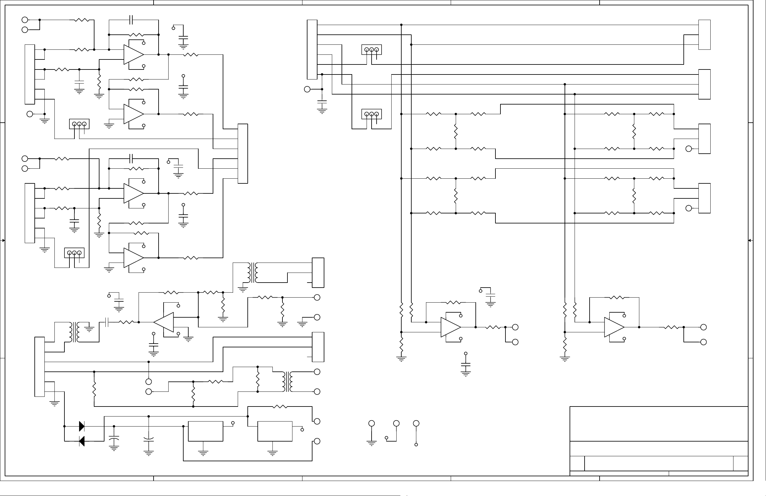
Title
SCHEMATIC: MULTIPORT INTERFACE PANEL
Size Document Number Rev
B
6300 A
2
Date: Sheet
1
HENRY ENGINEERING
503 Key Vista Drive
Sierra Madre, CA 91024 USA
telephone - (626) 355-3656
FAX (626) 355-0077
1
11Tuesday, February 09, 2010
of
 Loading...