

Page 1

TM
!"#$I&H(NE+ II
MULTI-USER HEADPHONE SYSTEM WITH ZONED TALKBACK
HENRY ENGINEERING
503 Key Vista Drive
Sierra Madre, CA 91024
Tel: 626.355.3656
Fax: 626.355.0077
www.henryeng.com
DESCRIPTION
MultiPhones II is a multi-user distributed stereo headphones system for broadcast studio, professional audio,
commercial sound and similar applications. It provides independent stereo headphone listening and three-zone
Talkback facilities for multiple users. The MultiPhones II system consists of the Master unit and up to 12 satellite
Guest Pods which are interconnected using standard CAT5 cabling. (This manual covers the Master unit only.)
WARNING! For 230V operation, change mains voltage jumpers before connecting to AC power!
Remove jumpers between E7 & E8, and between E6 & E9. Install a jumper between E6 & E7 for 230V; replace
fuse with .125a fuse. See schematic on reverse side. Jumpers should be changed by a qualified technician only.
INSTALLATION
Audio and control inputs for the MultiPhones II Master unit are via plug-in euroblock connectors. Remove about 1/8” of
insulation, insert the wires into the plugs, and tighten the screws. Be certain that no bare wires are exposed.
The MultiPhones II Master unit has two inputs: Program and Talkback. The Program input is for ‘normal’ stereo audio, e.g., the
Headphone output of a mixing console. Connect to the INPUT L and R terminals. For unbalanced sources, tie the – and G
inputs together. The audio input level should be between -15 and 0 dBm.
The Talkback input is for a (mono) Talkback mic or line level Talkback audio. Any balanced lo-z mic can be used. Connect to
the TALKBACK IN terminals. For unbalanced sources, tie the – and G terminals together. NOTE: The unit is shipped with the
Talkback input set to MIC; to use a LINE level talkback audio source, open the chassis and set JP1 to L.
There are three Talkback zones: A, B, and C. The Talkback function for each zone can be remotely activated with an external
contact closure (e.g., a SPST momentary switch or button) to ground. Use the TALKBACK REM terminals to connect contact
closures (one for each zone) between A, B, and/or C and G (ground).
Three RJ45 GUEST POD outputs on the rear of the unit are for connection to the MultiPhones II Guest Pods. All outputs feed
the same Program audio to the Guest Pods, but each RJ45 connector is for a separate Talkback zone. Use standard CAT5
cabling; in most cases unshielded cabling can be used. Up to 12 Guest Pods can be driven by the Master unit. It doesn’t matter
how many Guest Pods are connected to each RJ45 connector, as long as the total does not exceed 12 units.
NOTE: If Guest Pods are connected while the Master unit is plugged into AC
wait a few seconds, then plug it back in.
CALIBRATION AND SETUP
Once MultiPhones II has been installed, the audio levels should be calibrated. Set the L and R MASTER trimmers fully CCW.
Feed Program audio into the system, and monitor the output with a pair of headphones plugged into any Guest Pod. Set the
LEVEL knob to about 2 o’clock, and adjust the MASTER L and R trimmers for the desired level.
To set the Talkback level, press the appropriate TALKBACK button on the Master unit. Speak into the Talkback mic and adjust
the MASTER TB trimmer for adequate talkback audio level.
OPERATION
The MultiPhones II system is simple in its operation. The Guest Pod LEVEL control adjusts the audio level to the PHONES
jacks. Do not use both jacks at the same time. Use headphones between 24 and 600 ohms. Do not use 8-ohm headphones.
MultiPhones II II has three Talkback zones: A, B, and C. Pressing the Talkback button for any zone will “dim” the regular
Program audio and feed Talkback audio to the Guest Pods in that zone only. Any combination of Talkback buttons can be
pressed at the same time. Release the Talkback button(s) to restore normal Program audio.
SPECIFICATIONS
PROGRAM INPUT LEVEL -15 to 0 dBu, stereo, 10K bal or 5K unbal
TALKBACK INPUT LEVEL Either balanced mic or line, selectable, mono
FREQUENCY RESPONSE 5 Hz – 20 kHz, +/- 0.25 dB
DISTORTION .005% typical
NOISE -80 dBm typical
OUTPUTS Up to 12 Guest Pods in 3 Talkback zones
TALKBACK CONTROL GPI ground closure, 3X
POWER INPUT 115 OR 230 VAC, 50-60Hz, 9 W
APPROVALS City of Los Angeles Elect. Test Lab, CE
CONSTRUCTION Steel enclosure
PHYSICAL DIMEN 5.75”w X 5.50”d X 1.60”h, 3 LBS
Specifications subject to change without notice. Rev. 2/07
, it will be necessary to unplug the Master unit,
Page 2
5
4
3
2
1
RP1C 4.99K
65
PGM INPUT
J1
IN L+
IN L-
GND
D D
IN R+
IN R-
GND
C C
1
2
3
4
5
6
C2
.001uF
C7
.001uF
RP9C 4.99K
C22 30pF
65
TB CONTROL
J2
TB IN+
TB IN-
GND
TB 1
TB 2
TB 3
B B
E10
1
2
3
4
5
6
C10
.001uF
RP9A 4.99K
1 2
RP9B 4.99K
C11
.001uF
RP9D
4.99K
43
8 7
LED2
R68
2.7K, 5%
2
3
"
-8V
!
+8V
8 4
U8A
NE5532
C23
30pF
TBSW1A
E11
TBSW1B
E12
R70 100K
LED3
R69
2.7K, 5%
TBSW2A
E13
R71 100K
1
RP1A 4.99K
1 2
RP1B 4.99K
C1
.001uF
RP2A 4.99K
1 2
RP2B 4.99K
C8
.001uF
M
TB SENS
43
43
TB LEVEL
R49
100K
R40 1.00K
123
L
JP1
C28
.1uF
C29
.1uF
8 7
8 7
RP1D
4.99K
RP2D
4.99K
1 3
"
2
!
3
8 4
RP2C 4.99K
"
6
!
5
8 4
2
R41
100K 40%
R42
10.0K
6
5
-8V
+8V
U1A
NE5532
-8V
+8V
U1B
NE5532
"
-8V
!
+8V
8 4
U8B
NE5532
1
65
7
7
R31
1K 40%
2
MASTER-L
1 3
R56
100
R45
1K 40%
2
MASTER-R
1 3
R57
100
TB DUCK LEV
C12
1 3
!
100uF 16V
2
R67
100 40%
R29
10.0K
RP3A 10.0K
1 3
Q1
J174
2
2
RP4A 10.0K
RP5A 10.0K
1 3
Q3
J174
2
2
RP6A 10.0K
RP7A 10.0K
1 3
Q7
J174
2
2
RP8A 10.0K
Q2
J174
12
12
Q4
J174
12
12
Q8
J174
12
12
13
13
13
R4 1.00K
R60 1.00K
R35 1.00K
R15 1.00K
R19 1.00K
R66 1.00K
TBSW2B
LED4
RP3B 10.0K
4 3
C3 30pF
"
2
3
2
3
2
3
4 3
2
3
2
3
4 3
2
3
-8V
!
+8V
8 4
RP4B 10.0K
4 3
C6 30pF
"
-8V
!
+8V
8 4
RP5B 10.0K
4 3
C21 30pF
"
-8V
!
+8V
8 4
RP6B 10.0K
C9 30pF
"
-8V
!
+8V
8 4
RP7B 10.0K
4 3
C24 30pF
"
-8V
!
+8V
8 4
RP8B 10.0K
C27 30pF
"
-8V
!
+8V
8 4
1
U2A
NE5532
1
U3A
NE5532
1
U4A
NE5532
1
U5A
NE5532
1
U6A
NE5532
1
U7A
NE5532
RP3C 10.0K
6 5
RP4C 10.0K
6 5
RP5C 10.0K
6 5
RP6C 10.0K
6 5
RP7C 10.0K
6 5
RP8C 10.0K
6 5
LED1
RP3D 10.0K
8 7
C4 30pF
"
6
5
6
5
8 7
6
5
6
5
8 7
6
5
6
5
-8V
!
+8V
8 4
RP4D 10.0K
8 7
C5 30pF
"
-8V
!
+8V
8 4
RP5D 10.0K
C20 30pF
"
-8V
!
+8V
8 4
RP6D 10.0K
8 7
C19 30pF
"
-8V
!
+8V
8 4
RP7D 10.0K
C25 30pF
"
-8V
!
+8V
8 4
RP8D 10.0K
8 7
C26 30pF
"
-8V
!
+8V
8 4
7
U2B
NE5532
7
U3B
NE5532
7
U4B
NE5532
7
U5B
NE5532
7
U6B
NE5532
7
U7B
NE5532
RP10A 47
RP10B 47
4 3
RP10C 47
6 5
RP10D 47
8 7
RP11A 47
RP11B 47
4 3
RP11C 47
6 5
RP11D 47
8 7
RP12A 47
RP12B 47
4 3
RP12C 47
6 5
RP12D 47
8 7
R47 2.2 1/2W
R48 2.2 1/2W
12
12
12
J3
1
2
3
4
5
6
7
8
J4
1
2
3
4
5
6
7
8
J5
1
2
3
4
5
6
7
8
OUT1 L+
OUT1 L-
OUT1 R+
GND
OUT1 R-
PWR-
PWR+
OUT2 L+
OUT2 L-
OUT2 R+
GND
OUT2 R-
PWR-
PWR+
OUT3 L+
OUT3 L-
OUT3 R+
GND
OUT3 R-
PWR-
PWR+
R73
E14
TBSW3A
E15
TBSW3B
A A
5
2.7K, 5%
R72 100K
C30
.1uF
BLK
E1
AC
115V: 250 ma; 230V: 125ma
F1
E7
230V
1
PRI SEC
E6
2
3
5
6
7
D1
1N4004
115V
AC
E2
WHT
E4
GROUND TIE
E3
4
C31
.01uF
E8
E9
4
SPW-102
8
T1
3
D3
1N4004
D2
1N4004
R58 2.7K, 5%
D4
1N4004
C14
1000uF 25V
C13
1000uF 25V
C15
10uF
C16
10uF
2
+8V
-8V
C17
.1uF
C18
.1uF
C32
.1uF
C33
.1uF
TP2
TP3
NOTE: UNLESS OTHERWISE SPECIFIED
1
TP1
1
1
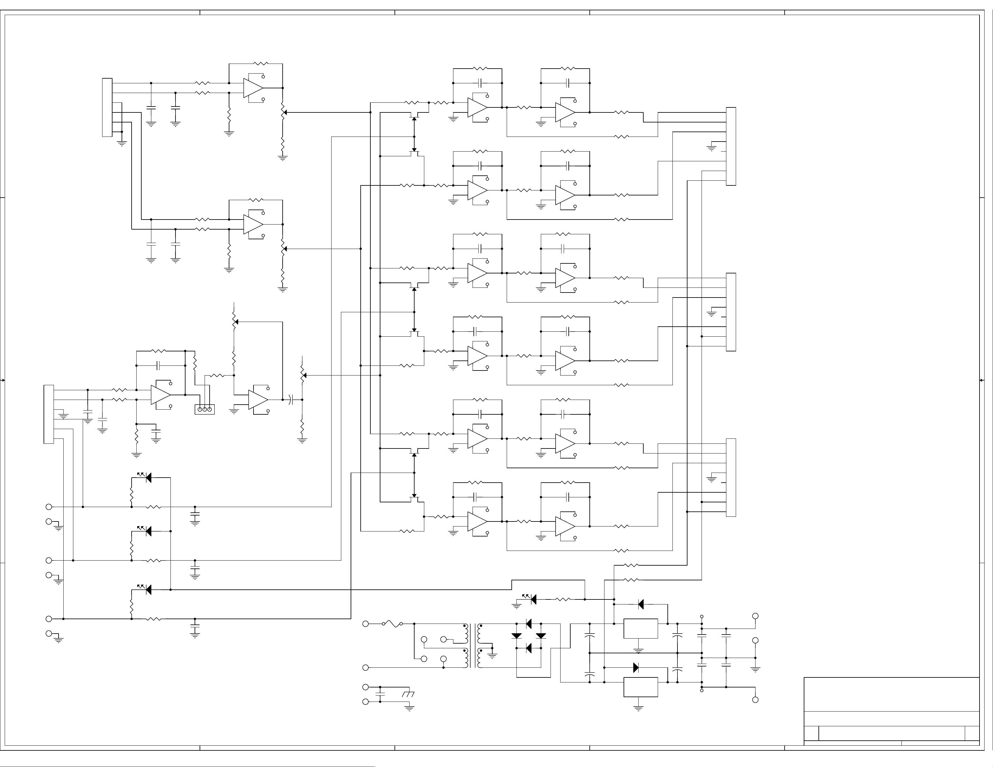
1. ALL RESISTORS ARE 1/4W, 1%.
HENRY ENGINEERING
503 Key Vista Drive
Sierra Madre, CA 91024 USA
telephone - (626) 355-3656
Title
Size Document Number Rev
Date: Sheet of
SCHEMATIC: MULTIPHONES II
C
!"#$ %
FAX (626) 355-0077
1
1 1Tuesday, January 30, 2007
D5 1N4004
3
IN
!
!
2 3
GND
2
D6 1N4004
IN OUT
GND
1
OUT
Q5
LM78L08
Q6
LM79L08
1
!
!
 Loading...