

Page 1

TM
MIXER MATE
Microphone and Monitor Controller
HENRY ENGINEERING
503 Key Vista Drive
Sierra Madre, CA 91024
tel: 626.355.3656
fax: 626.355.0077
website: www.henryeng.com
DESCRIPTION
Mixer Mate is a Microphone and Monitor Controller that allows popular “live music” audio mixers to be used in a
broadcast environment. Mixer Mate adds three important functions to the mixer: (a) it provides convenient On/Off
control of up to four microphones, (b) it mutes the Monitor audio when a microphone is in use, and (c) it provides
control of On The Air studio warning lights.
INSTALLATION
Mixer Mate utilizes the mixer’s “Mic Process Insert” facility to switch microphone audio on or off. Up to four mics
can be independently controlled via the unit’s front panel pushbuttons. Connect the mixer’s Process Insert circuit to
Mixer Mate via the four ¼” TRS (tip-ring-sleeve) jacks on the rear panel. Wire the Mixer Mate TRS plugs as follows:
TIP: From mixer’s mic preamp output
RING: To mixer’s mic channel return input
SLEEVE: To mixer ground
In most cases, a simple TRS patchcord can be used to connect the mixer and the Mixer Mate together.
Mixer Mate provides a Monitor Mute facility so that Monitor audio can be muted when selected microphones are in
use. Connect the Monitor output of the mixer to the Monitor Mute/IN jacks on the Mixer Mate (The top jack is left;
the bottom jack is right.) Connect the Monitor Mute/OUT jacks on Mixer Mate to the Line input of the monitor
amplifier. Warning: Do not connect directly to the high-power speaker outputs of the monitor amplifier.
Mixer Mate also provides a means of controlling “On The Air” studio warning lights, switching the lights on
whenever any microphone is in use. Warning: Do not connect 115 volt AC circuits directly to the Mixer Mate!
The best way to control warning lights is with a Henry Engineering Superelay. The Mixer Mate interfaces to the
Superelay via the 1/8” TRS mini-jack on the rear of the unit. Wire an 1/8” plug as follows and connect to the
Superelay CONTROL INPUT connector:
TIP: To Superelay “12V” terminal
RING: To Superelay “+ IN” terminal
SLEEVE: To Superelay “G” terminal
Note: When connected as above, Mixer Mate is powered by the Superelay. Do NOT connect any external power
supply to the +12VDC jack on the Mixer Mate. (The external power supply should be used only if the Mixer Mate is
NOT used with a Superely.)
MONITOR MUTE PROGRAMMING
Mixer Mate can be programmed to mute the Monitor system when selected microphones are in use. Select the
mics that will activate the Monitor Mute function using the MON MUTE SELECT “dip” switches on the rear of the
unit. There is a switch for each mic; if the switch is DOWN, the Monitor audio will mute when that microphone is on.
OPERATION
The microphones are turned on or off via the front panel pushbuttons. The LED above each button will light to
indicate that the mic is on. The Monitor system will mute whenever selected mics are on. Tally lights will be active
whenever any mic is on. Note that the mic on/off function will still operate even if the Mixer Mate is not powered-up.
Power is required to activate the Monitor Mute and Tally light functions, as well as illuminate the front panel LEDs.
SPECIFICATIONS
Mic On/Off control Line level, unbalanced, ¼” TRS jacks
Monitor Mute control Line level, unbalanced, RCA jacks
Monitor Mute programming Selectable for each microphone
Mic Tally output 12 VDC, when any microphone is on
Power Requirement 12 VDC, from Superelay or included power supply
Approvals CE, UL (power supply)
Construction Steel enclosure
Physical 5.75”w X 5.50”d X 1.60”h, 3 LBS
Specifications subject to change without notice. Rev C. 10/07
Page 2
5
4
3
2
1
J1
D D
MIC 1
R
T
S
R2
R1
100
10K
+12V
12
10
S1A
3
1
9
7
6
4
S1B
S1C
S1D
2
8
5
11
S5A
1 8
LED1
R3 2.4K
D1 1N4004
D5
1N4004
13
16
K1
4
1
6
8
11
9
MONITOR
J5A
2 1
J5C
5 4
J5B
3 1
J5D
6 4
L IN
L OUT
R IN
R OUT
-12V
J2
MIC 2
C C
R
T
S
R5
R6
100
10K
+12V
12
10
S2A
3
1
9
7
6
4
S2B
S2C
S2D
2
8
5
11
S5B
2 7
LED2
D2 1N4004
R4 2.4K
-12V
-12V
R14 100
+12V
+12V
-12V
5
2
1
J6
TALLY OUT
POWER IN
E2
-12V IN
-12V
+12V
E1
+12V IN
E3
CONNECT
TO
CHASSIS
VIA MTG.
SCREW
Title
NOTE: UNLESS OTHERWISE SPECIFIED
1. ALL RESISTORS ARE 1/4W, 5%.
HENRY ENGINEERING
503 Key Vista Drive
Sierra Madre, CA 91024 USA
telephone - (626) 355-3656
FAX (626) 355-0077
-12V
R13
2.4K
LED5
J3
MIC 3
B B
R
T
S
R8
R7
100
10K
+12V
12
10
S3A
3
1
9
7
6
4
S3B
S3C
S3D
2
8
5
11
S5C
3 6
LED3
D3 1N4004
R9 2.4K
-12V
J4
MIC 4
A A
R
T
S
R12
R11
100
10K
+12V
12
10
S4A
3
1
9
7
6
4
S4B
S4C
S4D
2
8
5
11
S5D
4 5
LED4
D4 1N4004
R10 2.4K
-12V
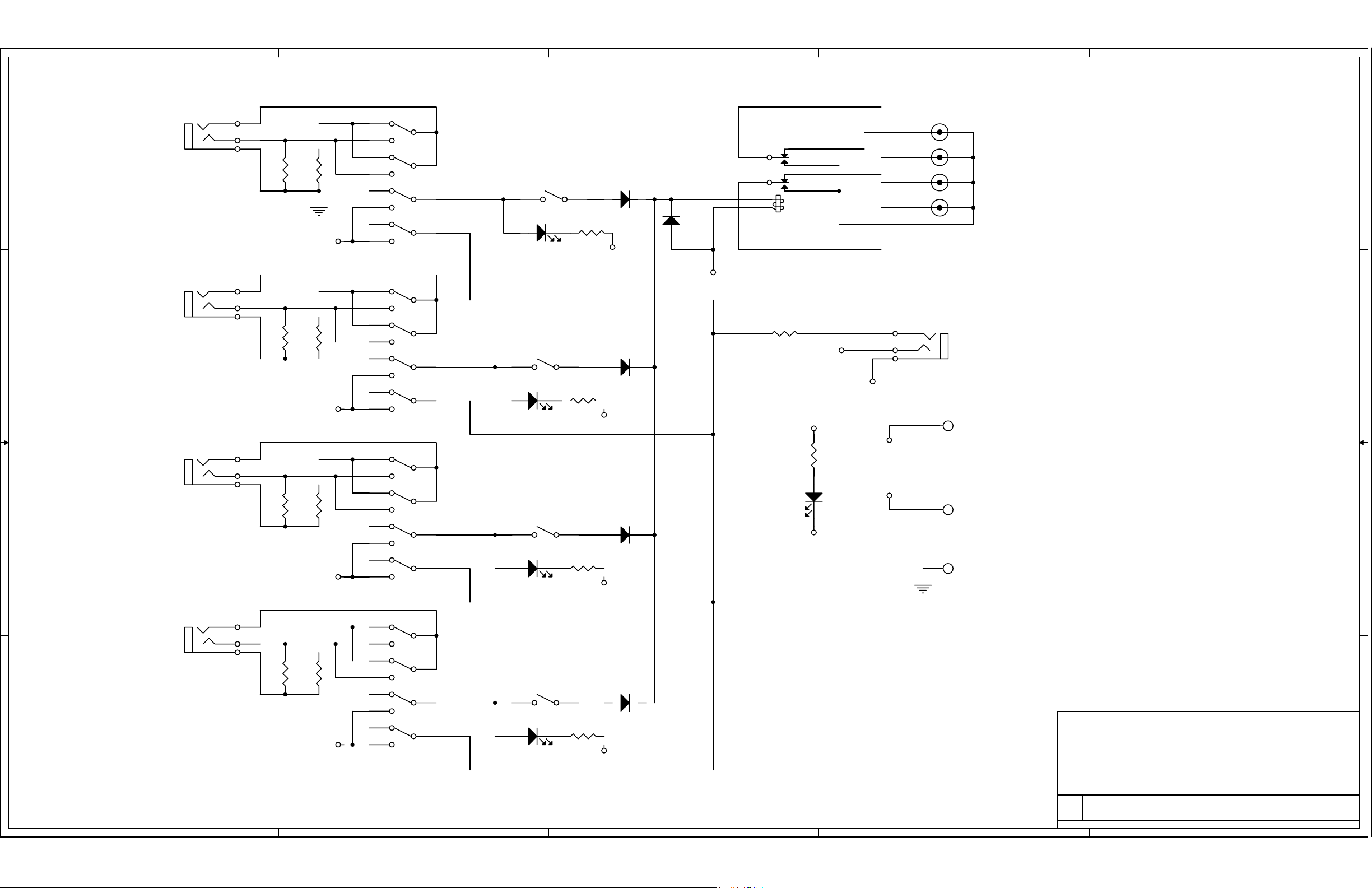
SCHEMATIC: MIXER MATE
Size Document Number Rev
B
3800 A
5
4
3
2
Date: Sheet of
1
11Friday, April 06, 2007
 Loading...