

Page 1

TM
MULTIPHONES MINI POD
FOR USE WITH MULTIPHONES HEADPHONES SYSTEM
DESCRIPTION
The MultiPhones Mini Pod is an individual headphone listening station for use with the MultiPhones Distributed
Headphones System. It receives power and Program and Talkback audio from the MultiPhones Master unit.
The Mini Pod can also be used as a “stand alone” headphone listening station (without a MultiPhones Master unit)
if external 12 VAC powering is provided. The Mini Pod includes a headphone amplifier with Level control, and both
¼” and 3.5mm headphone jacks.
INSTALLATION
The Mini Pod is designed for either tabletop or under-counter installation. For tabletop use, install the rubber
“bumpers” on the bottom side of the enclosure. Another option is to affix the unit to the tabletop using foam
mounting tape. For under-counter installation, either foam mounting tape or screws can be used. To screw the unit
to the underside of a counter, first open the Mini Pod enclosure be removing the four corner screws from the bottom
of the unit. Remove the top of the “clamshell” enclosure. Drill screw holes in the top as necessary, and screw the
top to the underside of the countertop. Re-attach the unit the lower section to the top with the bottom screws.
For use with MultiPhones Master unit:
cabling. In most cases, unshielded cables can be used. WARNING! DO NOT USE “CROSSOVER” CABLES!
Cat5 cables are available from any computer supplier, office supply retailer, or electronic parts distributor. (Staples,
Office Depot, Mouser Electronics, CyberGuys, Radio Shack, etc.)
Connect up to 3 Mini Pods directly to the MultiPhones Master unit. Each Mini Pod has 2 RJ45 connectors, which
are wired in parallel. (Use either connector.) Additional Mini Pods can be “daisy chained” together in any
combination. The total number of Mini Pods should not exceed 12 units.
NOTE: If Mini Pods are connected while the MultiPhones Master unit is on, it will be necessary to unplug
the Master unit, wait a few seconds, then plug it back in.
For use as a “stand alone” headphone listening station:
of 12 volt AC power. Any 12 volt AC adaptor can be used; the current requirement is about 50 ma. (Use Mouser
P/N 412-212054.) Two ¼” TRS input jacks on the rear panel accept stereo balanced audio at about 0 dBu.
Wire the inputs as follows: Tip = High; Ring = Low; Sleeve = Ground.
Multiple Mini Pods can be used by “daisy chaining” them together with cat5 cabling. Both power and audio will be
distributed to all Mini Pods via the cat5 cables. (To distribute power but not audio, remove R19, R20, R21, & R22
from each Mini Pod unit in the system.)
OPERATION
The Mini Pod is simple in its operation. The LEVEL controls adjust the audio level to the PHONES jacks. Do not
use both jacks at the same time. Use headphones with an impedance between 24 and 600 ohms. Do not use
older “8-ohm” headphones. When the Talkback function on the MultiPhones Master unit is in use, normal
Program audio will be overridden with Talkback audio.
SPECIFICATIONS
INPUT From MultiPhones Master unit or
¼” TRS jacks, 2X, 0 dBu, balanced 20K
OUTPUT For 24 – 600 ohm headphones, ¼” and 3.5mm jacks
FREQUENCY RESPONSE 5 Hz – 20 kHz, +/- 0.25 dB
DISTORTION .005% typical
NOISE -80 dBm typical
POWER INPUT Supplied by MultiPhones Master unit or 12 VAC, 50ma
PHYSICAL DIMEN 4”W x 6”D x 1 1/2” H, 1 LB
Specifications subject to change without notice. Rev. 1/08
The Mini Pod(s) is connected to the MultiPhones Master unit using cat5
For “stand alone” use, the Mini Pod requires a source
HENRY ENGINEERING
503 Key Vista Drive
Sierra Madre, CA 91024
Tel: 626.355.3656
Fax: 626.355.0077
www.henryeng.com
Page 2
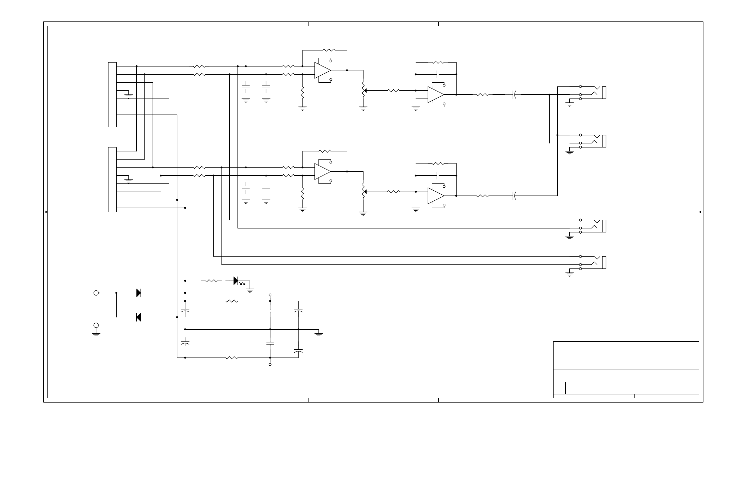
5
INPUT AND
LOOP-THRU
J1
IN L+
D D
IN L-
IN R+
GND
CONTR
IN R-
PWR IN-
PWR IN+
IN L+
IN L-
C C
IN R+
GND
CONTR
IN R-
PWR IN-
PWR IN+
1
2
3
4
5
6
7
8
J2
1
2
3
4
5
6
7
8
R19 1.00K
R20 1.00K
R21 1.00K
R22 1.00K
4
RP1C 4.99K
6 5
C2
.001uF
C7
.001uF
RP1A 4.99K
1 2
RP1B 4.99K
C1
.001uF
RP2A 4.99K
1 2
RP2B 4.99K
C8
.001uF
43
43
8 7
8 7
RP1D
4.99K
RP2D
4.99K
-
2
+
3
8 4
RP2C 4.99K
6 5
-
6
+
5
8 4
-8V
+8V
U1A
NE5532
-8V
+8V
U1B
NE5532
1
7
3
PHONES
LEV
3
VR1A
10K, 18%
4 2
PHONES
LEV
6
VR1B
10K, 18%
5 1
RP1E 4.99K
RP2E 4.99K
2
R7 12.1K
C3 30pF
-
109
109
2
+
3
8 4
U2A NE5532
R13 12.1K
C4 30pF
-
6
+
5
8 4
U2B NE5532
-8V
-8V
1
+8V
7
+8V
R25 47
R26 47
C19
+
220uf,16V
C20
+
220uf,16V
R
T
S
5
2
1
R
T
S
J3
PHONES 1/4"
J4
PHONES 3.5MM
J5
LEFT IN
1
B B
R15 3.9K
PWR
E1
E2
GND
A A
D1 1N4004
D2 1N4004
+
+
C14
330uF,35V
C13
330uF,35V
LED1
R27 220
R28 220
+8V
-8V
C17
.1uF,50V
C18
.1uF,50V
+
+
C21
330uF,25V
C22
330uF,25V
Title
R
T
S
J6
RIGHT IN
NOTE: UNLESS OTHERWISE SPECIFIED
1. ALL RESISTORS ARE 1/4W, 1%.
HENRY ENGINEERING
503 Key Vista Drive
Sierra Madre, CA 91024 USA
telephone - (626) 355-3656
FAX (626) 355-0077
SCHEMATIC, MINI GUEST POD
Size Document Number Rev
B
5500 C
5
4
3
2
Date: Sheet of
1
11Tuesday, March 18, 2008
 Loading...