

Page 1

HENRY ENGINEERING
MICROMIXER
FOUR INPUT STEREO MIXER
DESCRIPTION
MICROMIXER is a four-input, two-output stereo mixer/combiner for utility use. The unit has
balanced bridging inputs for four audio sources (two stereo pairs) which can be mixed to two
outputs (one stereo pair). A level control is provided for each input. Selectable 'assign'
switching permits any input to be fed to either or both outputs. DC coupled circuitry provides
excellent sonic performance.
INSTALLATION
All connections to the MicroMixer are made via plug-in connectors. Remove about 1/8” of
insulaton, insert wires into the plug, and tighten the screws. Be sure that no bare wires are
exposed.
Audio inputs to the MicroMixer should be connected to the balanced input terminals labeled 1, 2,
3, and 4. For unbalanced inputs, install a jumper between the (-) terminal and G (ground). All
inputs are bridging; it is not necessary to terminate the source unless required by the source
equipment.
Audio outputs from the MicroMixer are connected to the two outputs labeled L (Left) and
R (Right). The output circuitry will drive any load of 600 ohms or higher. It is not necessary to
terminate the outputs. For unbalanced outputs, connect to the (+) and G terminals only. DO
NOT short the (-) terminal to ground.
OPERATION
The input levels to the MicroMixer should be between -10 and +8 dBm. Adjust each input
channel using the INPUT LEVEL controls. Unity gain is achieved with these controls set to 10
o'clock; with nominal input levels of +4 dBm the Input Level controls should be run near this
setting. It is recommended that input levels be initially set with a level indicator (VU meter,
scope, VOM) temporarily connected to the MicroMixer's output to monitor output levels. The
average output level should not exceed +8 dBm to ensure adequate headroom.
Each output channel (L & R) has four ASSIGN switches that determine which of the four input
signals are fed to that output. Select the input sources desired by switching the appropriate
channels ON (down). For example, if inputs 1 and 3 should be fed to the LEFT output, set Left
output assign switches 1 and 3 ON, with 2 and 4 OFF.
SPECIFICATIONS
INPUTS -10 to +8 dBm; balanced 20K or unbalanced 10K
GAIN 10 dB maximum
OUTPUTS +4 dBm nominal, +26 dBm max; 600 ohms or higher, 4X
FREQ RESP DC to 20 kHz, +/- 0.25 Db
NOISE 80 dB below +4 dBm output
DISTORTION .008% IM/THD
503 Key Vista Drive
Sierra Madre, CA 91024
tel: 626.355.3656
fax: 626.355.0077
website: www.henryeng.com
Page 2
of
11Wednesday, December 10, 2003
1
GND
3
RIGHT
+
4
503 Key Vista Drive
Sierra Madre, CA 91024 USA
telephone - (626) 355-3656
-
GND
1. ALL RESISTORS ARE 1/4W, 1%.
5
6
NOTE: UNLESS OTHERWISE SPECIFIED
HENRY ENGINEERING
FAX (626) 355-0077
LEFT
+
-
1
J3
2
1
OUTPUTS
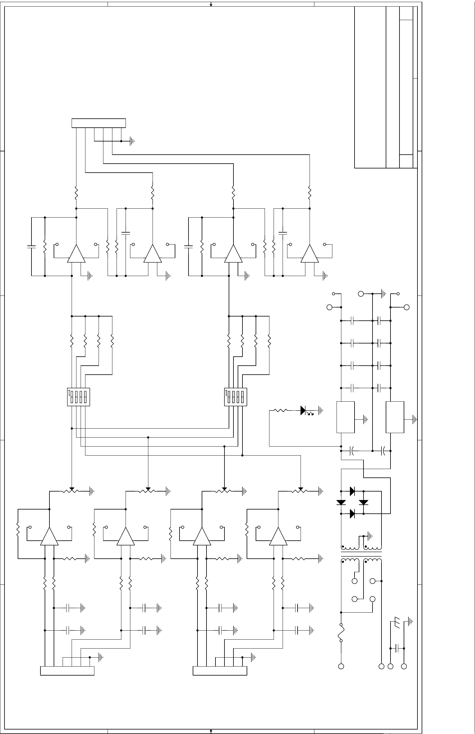
3510 A
SCHEMATIC: MICROMIXER
B
Title
Size Document Number Rev
Date: Sheet
R25 47, 5%
2
U3B
NE5532
C9 100pF
R26 7.50K
7
-15V
-
6
+15V
+
8 4
5
1.00K
R27
1.00K
R28
C21 .001uF
-15V
R29 47, 5%
U3A
1
-
2
NE5532
+
3
+15V
8 4
C10 100pF
R33 7.50K
R34 47, 5%
U4A
NE5532
1
-15V+15V
-
2
+15V
+
8 4
3
R32 1.00K
1.00K
R31
C22 .001uF
-15V+15V
R30 47, 5%
U4B
7
-
6
NE5532
+
5
2
+15V
8 4
TP1
2
1N4004
1
C20
C18
C16
C14
.1uF
.1uF
.1uF
.1uF
Q2 LM7915
+
+15V
1
C19
1
OUT
IN
3
C17
C15
C13
+
.1uF
.1uF
.1uF
.1uF
GND
D1
TP2
116
215
RP3A 4.7K DIP
RP3B 4.7K DIP
RP3C 4.7K DIP
3
876
5
SW1
123
2
SW DIP-4
4
1 3
314
413
RP3D 4.7K DIP
2
1 3
RP3E 4.7K DIP
SW2
2
512
876
123
611
RP3F 4.7K DIP
5
4
1 3
RP3G 4.7K DIP
SW DIP-4
710
89
RP3H 4.7K DIP
R39
3.9K, 5%
LED1
2
LED
Q1 LM7815
C12
330uF 25V
1 3
IN OUT
2 3
-15V
1
TP3
GND
C11
330uF 25V
3
1
4
5
215
RP2B 4.7K DIP
U1B
7
-15V
-
6
RP1A 4.7K DIP
1 16
1
J1
+
INPUTS
NE5532
+
5
116
RP1B 4.7K DIP
2 15
2
-
1
GND
LEFT
R35
+15V
8 4
RP2A
C2
C1
3
5K POT
4.7K DIP
.001uF
.001uF
4
-
+
2
RIGHT
5
314
RP2C 4.7K DIP
6
GND
-15V
RP1C 4.7K DIP
U1A
-
2
3 14
1
R36
+15V
NE5532
+
8 4
3
413
RP2D
4 13
RP1D 4.7K DIP
C4
C3
5K POT
4.7K DIP
.001uF
.001uF
512
RP2E 4.7K DIP
U2B
7
-15V
-
6
5 12
RP1E 4.7K DIP
1
J2
+
INPUTS
NE5532
+
5
611
6 11
RP1F 4.7K DIP
2
3
-
GND
LEFT
R37
8 4
RP2F
C6
C5
3
5K POT
4.7K DIP
.001uF
.001uF
4
+
-
4
RIGHT
5
710
RP2G 4.7K DIP
6
GND
-15V
RP1G 4.7K DIP
U2A
-
2
7 10
1
R38
NE5532
+
8 4
3
89
RP2H
8 9
RP1H 4.7K DIP
5K POT
4.7K DIP
C8
.001uF
C7
.001uF
D2
1N4004
D4
1N4004
SEC
5
687
1
PRI
342
E6F1
230V
E7
BLK
E1
115V: 250 ma; 230V: 125ma
AC
D3
115V
1N4004
E9
E8
WHT
E2
AC
T1
SPW-061
C23
.01uF
E4
E5
GROUND TIE
4
BIPOLAR POWER SUPPLY
5
D D
C C
B B
A A
 Loading...