

Page 1

TM
GUEST POD
FOR USE WITH MULTIPHONES HEADPHONES SYSTEM
DESCRIPTION
The Guest Pod is an individual headphone monitoring station for use with the MultiPhones Distributed Headphones
System. It receives power and Program and Talkback audio from the MultiPhones Master unit. The Guest Pod
includes a headphone amplifier with Level control, and both ¼” and 3.5mm headphone jacks. A “Cough switch”
and “Mic” LED are also provided, which can be wired to the user’s audio console or other equipment.
INSTALLATION
Note: The Cough switch and Mic LED on the Guest Pod are not part of the MultiPhones/Guest Pod system per se.
They can be wired to the user’s audio console or other equipment as desired. To use the Cough button, install two
jumper wires from the Cough switch contacts to the terminals on the PC board marked B1 AND B2. The Cough
switch can now be wired by connecting to the connector block (J3) terminals marked SW N.O. To use the Mic
LED, wire to the connector block terminals marked LED+ AND LED- . Observe polarity. The 1K resistor (R15) on
the pc board is appropriate for 12 vdc. (For other voltages, change this resistor as needed: 24 vdc = 2K.)
The Guest Pod can be flush-mounted in a cabinet cutout, or mounted using the optional desktop chassis.
To mount in a cabinet, cut a rectangular hole, 1.25” h X 3.75” w, and mount the Guest Pod panel using four corner
screws. The Guest Pod can be recessed below the surface by routing around the outside of the panel, or by
mounting to the inside surface of the cabinet.
To use the optional desktop chassis, mount the Guest Pod into the chassis using the #6 screws supplied. For
desktop use, the open side of the chassis should be down. For under-counter installation, the open side of the
chassis should be up. Install four mounting screws as needed on 3.30”w X 1.50”d centers, and mount the chassis
to the desktop or counter.
The Guest Pod(s) is connected to the MultiPhones Master unit using CAT5 cabling. In most cases, unshielded
cables can be used. WARNING! DO NOT USE “CROSSOVER” CABLES! CAT5 cables are available from any
computer supplier, office supply retailer, or electronic parts distributor. (Comp USA, Staples, Office Depot, Mouser
Electronics, CyberGuys, Radio Shack, etc.)
Connect up to 3 Guest Pods directly to the MultiPhones Master unit. Each Guest Pod has 2 RJ45 connectors,
which are wired in parallel. (Use either connector.) Additional Guest Pods can be “daisy chained” together in any
combination. The total number of Guest Pods should not exceed 12 units.
NOTE: If Guest Pods are connected while the MultiPhones Master unit is on, it will be necessary to unplug
the Master unit, wait a few seconds, then plug it back in.
OPERATION
The Guest Pod is simple in its operation. The LEVEL controls adjust the audio level to the PHONES jacks. Do not
use both jacks at the same time. Use headphones with an impedance between 24 and 600 ohms. Do not use
older “8-ohm” headphones. When the Talkback function on the MultiPhones Master unit is in use, normal
Program audio will be overridden with Talkback audio.
SPECIFICATIONS
OUTPUT For 24 – 600 ohm headphones
FREQUENCY RESPONSE 5 Hz – 20 kHz, +/- 0.25 dB
DISTORTION .005% typical
NOISE -80 dBm typical
POWER INPUT Supplied by MultiPhones Master unit
PHYSICAL DIMEN 4.00”w X 3.00”d X 2.25”h, 1 LB
Specifications subject to change without notice. Rev. 11/04
HENRY ENGINEERING
503 Key Vista Drive
Sierra Madre, CA 91024
Tel: 626.355.3656
Fax: 626.355.0077
www.henryeng.com
Page 2
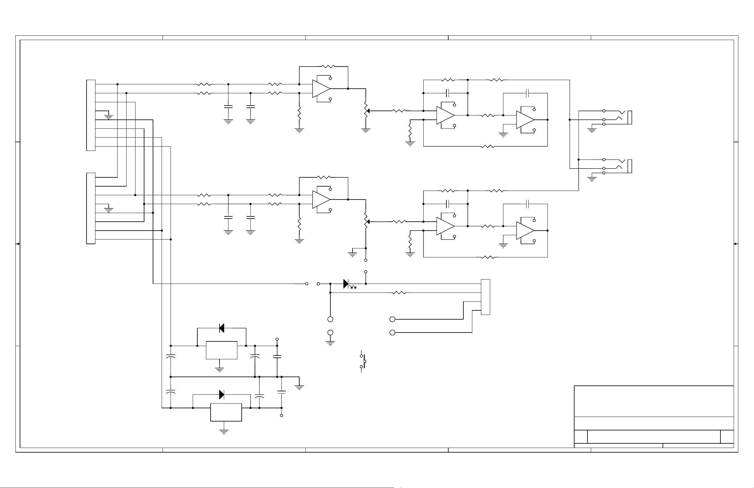
5
INPUT AND
LOOP-THRU
J1
IN L+
D D
IN L-
IN R+
GND
CONTR
IN R-
PWR IN-
PWR IN+
IN L+
IN L-
C C
IN R+
GND
CONTR
IN R-
PWR IN-
PWR IN+
1
2
3
4
5
6
7
8
J2
1
2
3
4
5
6
7
8
R19 1.00K
R20 1.00K
R21 1.00K
R22 1.00K
4
C2
.001uF
C7
.001uF
RP1A 4.99K
1 2
RP1B 4.99K
C1
.001uF
RP2A 4.99K
1 2
RP2B 4.99K
C8
.001uF
3
RP1C 4.99K
6 5
PHONES
-
-8V
2
43
8 7
RP1D
4.99K
3
RP2C 4.99K
6 5
+
8 4
1
+8V
U1A
NE5532
LEV
4 2
3
R4A
10K, 18%
RP1E 4.99K
109
R9
100
PHONES
-
-8V
6
43
8 7
5
RP2D
4.99K
+
8 4
7
+8V
U1B
NE5532
LEV
5 1
6
R4B
10K, 18%
RP2E 4.99K
109
R11
100
R7 12.1K
C3 30pF
-
2
+
3
8 4
U2A NE5532
R13 12.1K
C4 30pF
-
6
+
5
8 4
U2B NE5532
-8V
1
+8V
-8V
7
+8V
R25 10
R8 1Meg
R10 100K
R26 10
R23 1Meg
R24 100K
2
C5 .01uF
-
2
+
3
8 4
U3A LF353
C6 .01uF
-
6
+
5
8 4
U3B LF353
-8V
+8V
-8V
+8V
1
R
1
7
T
S
5
2
1
J4
PHONES 1/4"
J5
PHONES 3.5MM
JP1
JP2
B B
D1 1N4004
+8V
3
IN
C14
+
22uF
C13
+
A A
5
22uF
GND
2
D2 1N4004
2 3
IN OUT
GND
1
OUT
Q1
78L08
Q2
79L08
4
1
C15
+
22uF
+
C16
22uF
C17
.22uF
C18
.22uF
-8V
LED1
R15 1K
B1A1
A2
B2
S1
1. CONNECT S1 TO A1, A2 FOR MIC-MUTE CONTROL
2. CONNECT S1 TO B1, B2 FOR EXTERNAL USE
3. INSTALL JP1 AND JP2 FOR USE WITH CONSOLE CONTROLLER
3
J3
651-1935187
1
2
3
4
LED -
LED +
SW N.O.
SW N.O.
NOTE: UNLESS OTHERWISE SPECIFIED
1. ALL RESISTORS ARE 1/4W, 1%.
HENRY ENGINEERING
503 Key Vista Drive
Sierra Madre, CA 91024 USA
telephone - (626) 355-3656
Title
SCHEMATIC GUEST POD
Size Document Number Rev
B
4500 A
2
Date: Sheet
FAX (626) 355-0077
11Monday, October 11, 2004
1
of
 Loading...