

Page 1

TM
AUTOSWITCH
STEREO AUDIO SWITCHER + SILENCE SENSOR
DESCRIPTION
AutoSwitch is a versatile stereo audio switcher and silence sensor. It can be used to manually or automatically
select between two stereo audio sources. Manual source selection is controlled with a GPI contact closure or DC
voltage; automatic selection is via the silence sensor. When automatic operation is used, the silence sensor
monitors the “A Input” audio levels. If the level of either (or both) channels drops below the silence threshold for the
delay time preset, the unit switches to the “B Input”. When the A source audio returns, the unit resets and switches
back to the A input. The silence threshold and time delay are adjustable for each channel. An Alarm relay output is
provided to activate an external alarm or other equipment. Gain trims are provided for each audio input.
INSTALLATION
Audio and control circuits for AutoSwitch are via plug-in euroblock connectors. Remove about 1/8” of insulation,
insert the wires into the plugs, and tighten the screws. Be certain that no bare wires are exposed. Audio inputs
may be either balanced or unbalanced; for unbalanced sources, jumper the – input to GND. For unbalanced
outputs, connect to the + and GND terminals only. Do NOT short the – output to GND.
If manual control will be used to switch between A and B inputs, connect to the CONTROL connector as follows:
For GPI control (contact closure or open collector), connect to – and GND. (Open collector to –, Ground to GND.)
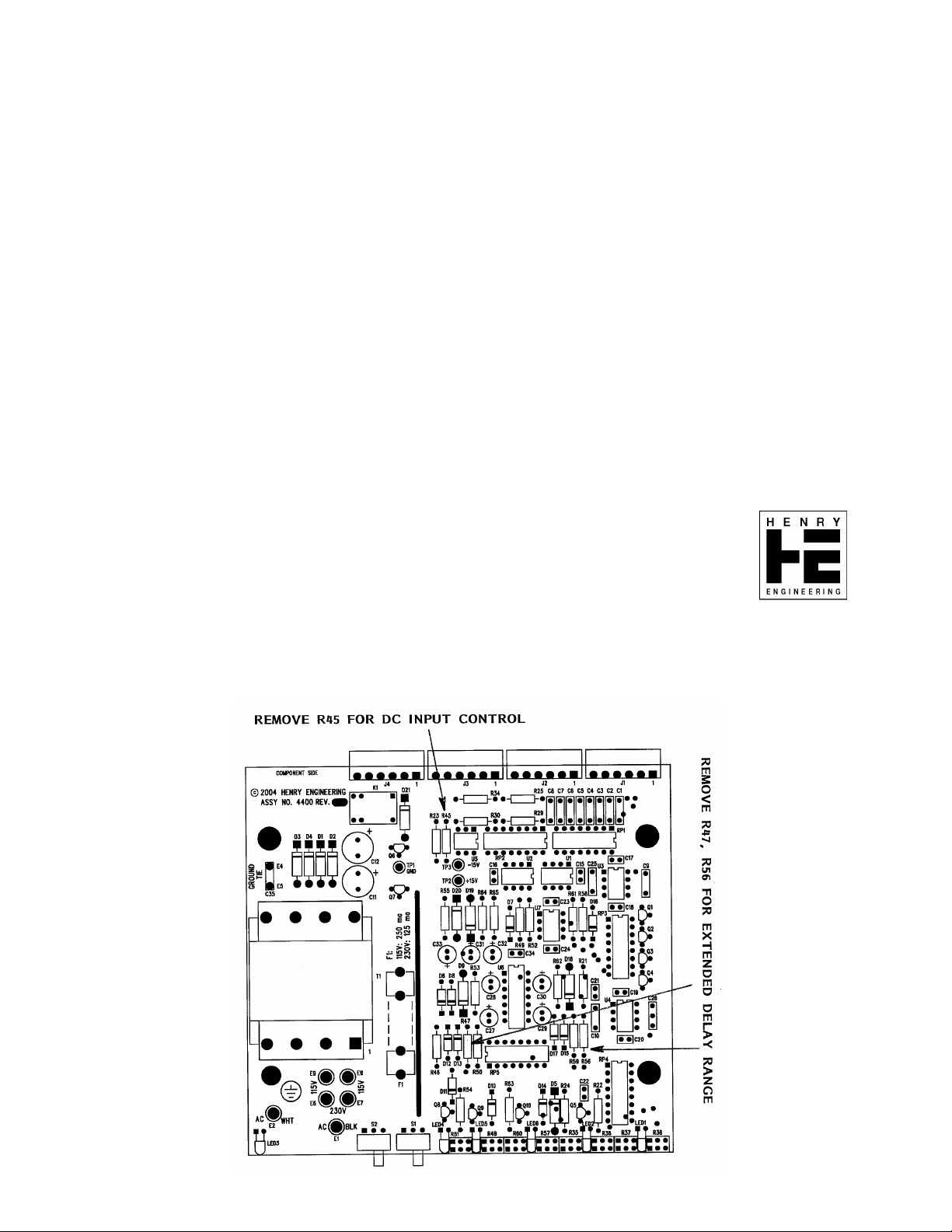
For control via a DC voltage, first open the unit and disconnect one end of R45, a 1K resistor. Connect the DC
control signal to the + and – control inputs. BE SURE to include a current limiting resistor in series with one input
lead! (For 5vdc to 12vdc, use 1K; for 24vdc, use 2K.)
AutoSwitch has an ALARM relay that activates when the silence sensor trips. Its terminals are on the CONTROL
connector. The NO and C terminals close when the silence sensor trips.
CALIBRATION AND SETUP
Once AutoSwitch has been installed, the audio levels and silence sensor adjustments should be calibrated.
Each audio input has a pair of level adjustments; adjust to produce the desired output level. (Unity gain is achieved
when the trimpots are set to mid-rotation.) Note that the unit will default to the A source, unless manually switched
to B, or unless the A audio level is below the silence sensor threshold. The GREEN LED indicates the active input.
To calibrate the silence sensor, set the SIL SEN and ALARM switches to ON.
The A source is always monitored by the silence sensor. There are separate level (LEV) and delay time (DEL)
adjustments for each (L&R) channel. The YELLOW LEDs will light whenever audio falls BELOW the silence
threshold. Turning the LEV trimmer clockwise INCREASES the threshold, making the silence sensor more apt to
trip. Turning the LEV trimmer counter-clockwise REDUCES the threshold, making the sensor less apt to trip.
Watch the yellow LEDs and adjust the LEV trimmers so the LEDs light when audio falls below the desired level.
The DELAY time trimmers determine the time the A-source audio must stay below the threshold before the silence
sensor trips. Turning the trimmer clockwise increases the delay time. The normal range is from 3 sec. to 20 sec.
(This range can be increased by removing R47 and R56. In this mode, the delay range will be from about 20 sec. to
35 sec.) NOTE: The shorter of the two delay settings always takes precedence: the unit will trip when the shorter
of the two delays “times out”. In most cases, the two delay trimmers should be set to about the same delay time.
The RED LED will indicate when the silence sensor has tripped. The GEEEN LED will confirm when the B audio
source is active.
HENRY ENGINEERING
503 Key Vista Drive
Sierra Madre, CA 91024
Tel: 626.355.3656
Fax: 626.355.0077
www.henryeng.com
Page 2
AUTOSWITCH MANUAL, PAGE 2
OPERATION
MANUAL MODE: To manually select between A and B source, set the SIL SEN switch to OFF.
In this mode, a maintained control input will switch from the A to the B source. If there is no control input, the A
source will be selected by default. The green LEDs indicate which audio source is active.
AUTOMATIC MODE: For automatic operation, set the SIL SEN switch to ON. In this mode, the silence sensor will
automatically switch to the B source if the A source fails, loses a channel, or if the audio level drops below the
threshold for the delay time set. The red LED indicates when the sensor has tripped; the green LEDs indicate
which audio source is active. When the A source audio returns, AutoSwitch will switch back to the A source.
The ALARM switch enables the alarm relay. If it is ON, the alarm relay will operate when the silence sensor trips.
The relay can be used to control an external alarm device or other equipment. If the ALARM switch is OFF, the
alarm relay is disabled, although the automatic audio switching function will remain active.
SPECIFICATIONS
INPUT LEVEL -6 to +4 dBu
INPUT IMPED 10K ohms bal, 5K ohms unbal
GAIN -6 to +6 dB
OUTPUT LEVEL +4 dBu nom, +24 dBu max
OUTPUT LOAD 600 ohms or higher per chan, bal
FREQ RESPONSE DC to 20 kHz, +/- 0.25dB
NOISE LEVEL 90 dB below +4 dBu output
DISTORTION .01%
MANUAL CONTROL Maintained contact closure or 5 – 24 VDC
SILENCE SENSE LEV 10 to 40 dB below normal level
SILENCE SENSE DEL 3 – 35 seconds in two ranges
ALARM RELAY SPDT dry contacts, 24VDC, 1A max
POWER INPUT 115/230 VAC, 50/60Hz, 3 W
APPROVAL City of Los Angeles Elect. Test Lab
CONSTRUCTION Steel enclosure
PHYSICAL DIMEN 5.75”w X 5.50”d X 1.60”h, 3 LBS
Specifications subject to change without notice. Rev. B 9/04
Page 3

5
RP1C 5.1K DIP
3 14
AIN/L+
AIN/L-
D D
A INPUT
L+
L-
GND
R+
R-
GND
J1
1
2
3
4
5
6
C1
.001uF
AIN/R+
AIN/R-
C3
C C
.001uF
BIN/L+
BIN/L-
B INPUT
J2
L+
1
L-
2
GND
R+
R-
GND
3
4
5
6
B B
BIN/R+
BIN/R-
C5
.001uF
C7
.001uF
RP1A 5.1K DIP
1 16
2 15
RP1B 5.1K DIP
C2
.001uF
5.1K DIP
RP1E 5.1K DIP
5 12
6 11
RP1F 5.1K DIP
C4
RP1H
.001uF
5.1K DIP
RP2A 5.1K DIP
1 16
2 15
RP2B 5.1K DIP
C6
.001uF
5.1K DIP
RP2E 5.1K DIP
5 12
6 11
RP2F 5.1K DIP
C8
.001uF
5.1K DIP
413
RP1D
89
413
RP2D
89
RP2H
CONTROL
J4
R
1
T
2
A A
S
3
4
5
6
RLY_NC
RLY_COM
RLY_NO
+15V
LED1
R45
U5
1K
4N25
1 6
2
5
+15V
5
4
R23
1Meg
-
6
+
5
8 4
RP3A 3.3K DIP
1 16
RP1G 5.1K DIP
7 10
-
2
+
3
8 4
RP3C 3.3K DIP
3 14
RP2C 5.1K DIP
3 14
-
6
+
5
8 4
RP3E 3.3K DIP
5 12
RP2G 5.1K DIP
7 10
-
2
+
3
8 4
RP3G 3.3K DIP
7 10
-15V
U1B
7
LF353N
+15V
-15V
U1A
1
LF353N
+15V
-15V
U2B
7
LF353N
+15V
-15V
U2A
1
LF353N
+15V
RP5G 3.9K DIP
7 10
C
1N4004
R24
100K
4
2
R35
10K 40%
1 3
2
R36
10K 40%
1 3
2
R37
10K 40%
1 3
RP3H 3.3K DIP
2
8 9
R38
10K 40%
1 3
D5
4
A
RP3B 3.3K DIP
2 15
B
RP3D 3.3K DIP
4 13
RP3F 3.3K DIP
6 11
+15V
R22
100K
C22
.1uF
Q1
J174
1 3
Q2
J174
1 3
Q3
J174
1 3
Q4
J174
1 3
LED2
2
2
2
2
RP5H 3.9K DIP
8 9
2N4401
Q5
R21
100K
C21
.1uF
3
1 16
-
6
+
5
8 4
2 15
3 14
-
2
+
3
8 4
6 11
-
2
+
3
8 4
7 10
8 9
-
6
+
5
8 4
E1
AC
115V: 250 ma; 230V: 125ma
E2
AC
E4
GROUND TIE
E5
3
-15V
+15V
-15V
+15V
C10 200pF
-15V
+15V
-15V
+15V
BLK
WHT
C35
.O1uF
C9 200pF
RP4A 3.3K DIP
U3B
7
NE5532
RP4B 3.3K DIP
RP4C 3.3K DIP
C25 200pF
U3A
1
NE5532
RP4F 3.3K DIP
U4A
1
NE5532
RP4G 3.3K DIP
RP4H 3.3K DIP
C26 200pF
U4B
7
NE5532
F1
2
E7
115V
E8
230V
R29
47
R34
47
R30
47
E6
R25
47
PRI
E9
OUT/R+
OUT/R-
1
2
3
4
SPW-061
OUT/L+
OUT/L-
5
SEC
6
D4
7
1N4004
8
T1
BIPOLAR POWER SUPPLY
2
R46
3.9K
LED3
C12
330uF 25V
330uF 25V
D2
1N4004
D3
1N4004
1
SPARE
RP4D 3.3K DIP
4 13
RP4E 3.3K DIP
C15
.1uF
C16
.1uF
5 12
+20V
+15V
C17
.1uF
C18
.1uF
-15V
OUTPUT
J3
+
C11
+
D1
1N4004
L+
1
L-
2
GND
3
R+
4
R-
5
GND
6
Q6 LM7815
3
IN
Q7 LM7915
2 3
IN OUT
NOTE: UNLESS OTHERWISE SPECIFIED
1. ALL RESISTORS ARE 1/4W, 5%.
TP2
1
1
OUT
GND
2
GND
1
1
TP3
HENRY ENGINEERING
503 Key Vista Drive
Sierra Madre, CA 91024 USA
telephone - (626) 355-3656
Title
SCHEMATIC: MONISWITCH
Size Document Number Rev
B
4400 A
Date: Sheet
FAX (626) 355-0077
1
12Wednesday, July 07, 2004
TP1
1
of
Page 4

5
4
3
2
+20V
1
ALARM OFF/ON
1
2
3
D D
S1
L TIME
R49 1.5meg
C27
10uF
C29
10uF
D6
1N4148
+
D15
1N4148
+
A
L THRESH
10K 50%
C C
R THRESH
B B
10K 50%
13
R51
R54
100
B
R60
R63
100
R52 10K
2
13
R61 10K
2
-
2
+
3
8 4
R58 1.5meg
-
6
+
5
8 4
-15VB
LF353N
+15VB
-15VB
U7B
LF353N
+15VB
U7A
1
7
D7
1N4148
D12
1N4148
D13
1N4148
D16
1N4148
D9
C28
10uF
6.2V
+
S2
1
2
3
SIL SENSE OFF/ON
D18
C30
10uF
6.2V
+
R53
10K
R62
10K
U6A
40106
R55 10K
U6F
40106
21
RP5A
3.9K DIP
1213
RP5E
3.9K DIP
116
Q9
2N4401
512
U6B
43
40106
LED5
L SENSE
U6E
1011
40106
LED6
D8
1N4148
RP5B 3.9K DIP
2 15
D17
1N4148
RP5F 3.9K DIP
6 11
R47 270K
R50 1.5meg
U6C
65
40106
D10
1N4148
D14
1N4148
U6D
89
40106
R48
1meg 50%
1 3
2
RP5C 3.9K DIP
3 14
R56 270K
R59 1.5meg
D21
1N4004
LED4
ALARM
Q8
2N4401
R TIME
R57
1meg 50%
1 3
2
K1
24VSPDT
1
2
5
RP5D 3.9K DIP
4 13
D11
1N4148
4
3
+15VB
RLY_COM
RLY_NC
RLY_NO
C
R SENSE
D19
+15V
A A
-15V
1N4004
D20
1N4004
+15VB
VDD
C34
.1uF
C24
.1uF
-15VB
C23
.1uF
R64
1K
R65
1K
C32
10uF
+
4
C31
+
10uF
C33
+
10uF
5
Q10
2N4401
HENRY ENGINEERING
503 Key Vista Drive
Sierra Madre, CA 91024 USA
telephone - (626) 355-3656
Title
SCHEMATIC: MONISWITCH
Size Document Number Rev
B
4400 A
3
2
Date: Sheet
FAX (626) 355-0077
of
1
22Monday, July 05, 2004
 Loading...