


AES DIGISWITCH 3X1
HENRY ENGINEERING
THREE-INPUT AES DIGITAL AUDIO SWITCHER PO Box 3796
Seal Beach, CA 90740
Tel: 562.493.3589
www.henryeng.com
DESCRIPTION
AES DigiSwitch 3X1 is a three-input digital audio switcher. It accepts up to three AES digital audio sources,
selecting one source that is routed to the AES output. It can be used as an AES source selector, or "in reverse" as
a router, sending an AES source to one of three destinations. All switching is via sealed relays. There is no active
circuitry in the signal path, hence all data remains bit-accurate with no added delay or latency. The unit can be
controlled by front panel pushbuttons and/or by any remote switch or contact closure, TTL/CMOS logic, or DC
voltage. Internal power-up programming permits the user to determine which input is automatically selected when
AC is applied. An optional Auto-Return mode automatically selects Input #1 if no other input is selected. Tally
outputs are provided to drive remote status LEDs. Input sources that are not selected are automatically terminated.
WARNING! For 230V operation, change mains voltage jumpers before connecting to AC power!
Remove jumpers between E6 & E7, and between E5 & E8. Install a jumper between E5 & E6 for 230V; replace
fuse with a .125a fuse. See schematic on reverse side. Jumpers should be changed by a qualified technician only.
INSTALLATION
All AES I/O is via standard XLR connectors. Pin 1 of all XLRs is connected to the AC safety ground and the units chassis.
AES DigiSwitch 3X1 can be controlled with any contact closure, open-collector, or by applying a DC voltage (5 - 24 VDC) from
an external source, e.g., the TTL or CMOS-level output of a computer interface or a logic circuit. Control inputs can be either
momentary or maintained.
Control logic programming: Before connecting control inputs, the user must determine the type of control that will be used,
and configure internal programming jumpers accordingly. There are 3 Control inputs, one for each audio source. Each Control
input can be set to accept one of 3 types of control input: (1) a contact closure that switches to ground, (2) a contact closure
that switches to a positive voltage, or (3) a DC voltage between 5 and 24 VDC.
The programming jumpers are located within the unit just behind the front panel. They and are marked JP1, JP2, and JP3, for
Control inputs #1, #2 and #3. Each set of programming jumpers has pin-pairs labeled A, B, and P.
To configure an input for control via any circuit that switches to a positive voltage, or to control by applying a DC voltage:
Install two jumpers in the A positions. To configure an input for control via any circuit that switches to ground: Install two
jumpers in the B positions. (DigiSwitch is shipped with this configuration preset.)
Connect Control inputs via the 9-pin D connector as follows:
Pin 1 Control #1 input Pin 4 Ground Pin 7 Tally #1 output
Pin 2 Control #2 input Pin 5 +12 VDC source Pin 8 Tally #2 output
Pin 3 Control #3 input Pin 6 Remote Disable Pin 9 Tally #3 output
Connect all control input signals between pin 4 (ground) and the desired Control input pin. For open-collector interface, connect
the emitter to pin 4 (Ground), and connect the open-collector to the appropriate Control input.
Power-up programming: Each set of programming jumpers has a P option to set the power-up programming. The input that
is selected with the P jumper will be automatically selected upon power-up. Install a P jumper in one input only. DigiSwitch is
shipped from the factory with the Input #1 P jumper set for power-up.
Auto-Return mode: AES DigiSwitch 3X1 can be configured to return to Input #1 if no other input is selected. This would be
applicable if external equipment provides a maintained closure when switching should occur, and the release of this closure is
used to return to input #1. To use the Auto-Return mode, 4 components must be installed on the DigiSwitch PC board: Two
1N4004 diodes (D6, D7), one 10K resistor (R3), and one 35uf/25v capacitor (C2). Install these components on the PC board
where indicated. Observe polarity.
NOTE: ALL of the power-up “P” jumpers must be removed when the Auto-Return mode is used.
To use the Auto-Return mode, ALL Control inputs must be configured for ground-closure use, with jumpers in the B
positions. Control inputs to #2 and/or #3 must be ground closures. Connect between pin 4 (ground) and the appropriate Control
input. DO NOT connect anything to Control input #1 (pin 1). Remove the “P” jumper.
PAGE 2
When either Input #2 or #3 is selected with a maintained closure, DigiSwitch will switch to that input. When the closure is
released, DigiSwitch will return to Input #1.
DigiSwitch provides TALLY outputs to drive external indicator LEDs. The Tally outputs are open collectors, which go LOW when
the input is active. Connect status LEDs between each TALLY output and +12V (pin 5) on the D connector.
Termination: AES DigiSwitch 3X1 is supplied with 110 ohm terminating resistors installed. Inputs that are not selected are
automatically terminated. To defeat this feature, remove the terminating resistors as needed:
INPUT #1: R17 INPUT #2: R19 INPUT #3: R21
OPERATION
Operation is straightforward. Activating any control input will select the corresponding audio source. Switching always occurs at
the leading edge the control input. Only one source can be selected at a time. Do not "overlap" control inputs; doing so will
lock-out all audio sources. The remote Tally indicators will follow whichever front panel pushbutton is illuminated.
Remote Disable: If the REMOTE DISABLE input (pin 6) is connected to GROUND (pin 4), ALL inputs will be OFF; no signal
will be sent to the OUTPUT. When the ground connection is released, the input previously active will return ON. Note that input
selection is still active even if the DISABLE function is used.
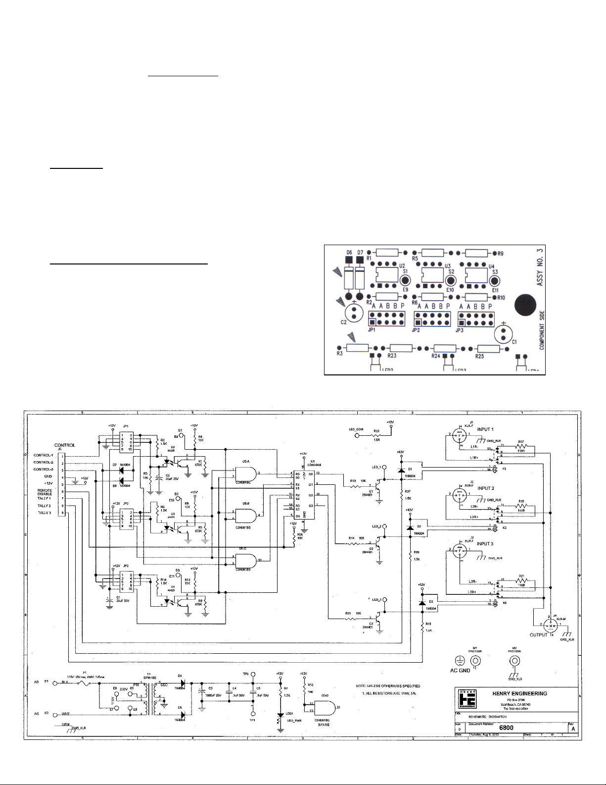
FOR AUTO-RETURN OPERATION
Install these components, see diagram at right:
D6, D7: 1N4004 diodes X2
C2: 35uF/25V capacitor
R3 10K ¼ W resistor
Install jumpers J1P, JP2, JP3 according to input
signal used for control. See text for details.
 Loading...