

Page 1

Supplied By www.heating spares.co Tel. 0161 620 6677
Page 2
Supplied By www.heating spares.co Tel. 0161 620 6677
WH FF (Natural Gas Models Only) PI No. 87 AP 107
WH 30 FF .................................G.C. No. 41 349 87
WH 40 FF .................................G.C. No. 41 349 88
WH 50 FF .................................G.C. No. 41 349 89
WH 60 FF .................................G.C. No. 41 349 90
WH 70 FF .................................G.C. No. 41 349 91
WH 80 FF .................................G.C. No. 41 349 92
WH100 FF .................................G.C. No. 41 349 93
Introduction
It is essential that the instructions in this booklet are
strictly followed, for safe and economic operation of
the boiler.
Current Gas Safety (Installation & Use)
Regulations or rules in force.
In your own interest, and that of safety, it is the law that this
boiler must be installed by a registered installer, in accordance
with all national and local regulations.
Electricity Supply
This appliance must be efficiently earthed.
Supply: 230 V ~ 50 Hz. The fusing should be 3A.
Connection must be made in a way that allows complete
isolation of the electrical supply such as a double pole switch
having a 3mm (1/8") contact separation in both poles, or a plug
and socket, serving only the boiler and system controls. The
means of isolation must be accessible to the user after
installation.
IMPORT ANT NOTES
a. This appliance must not be operated without the casing correctly
fitted and forming an adequate seal.
b. If the boiler is installed in a compartment then the compartment
MUST NOT be used for storage purposes.
c. The ventilation provided for the boiler during installation MUST
NOT be blocked, and a check should be made periodically that
the ventilation areas are free from any obstruction.
d. If it is known or suspected that a fault exists on the boiler then
it MUST NOT be used until the fault has been corrected by a
CORGI registered installer.
e. Flammable materials must not be placed in close proximity to
the appliance. Materials giving off flammable vapours must
not be stored in the same room as the appliance.
f. Under NO circumstances should any of the sealed components
on this appliance be used incorrectly or tampered with.
Minimum clearances
A clearance of 533mm (21") MUST be available at the front of the
boiler for servicing.
The minimum clearances given below MUST be complied with in
order to maintain the safe running of the boiler.
Above the boiler 100 mm (4")
At each side of the boiler 5 mm (
Underneath the boiler 100 mm (4")
In front of the boiler 75 mm (3")
1/4")
To light the boiler (refer to Frame 1)
If a timer is fitted refer to separate instructions for the timer before
continuing.
1. CHECK THAT THE ELECTRICITY SUPPLY TO THE BOILER
IS OFF.
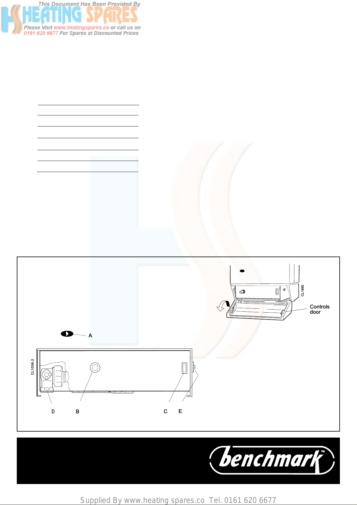
2. Open the controls access door by hinging downwards.
3. Ensure that the gas inlet cock (D) is OPEN.
4. Press the overheat reset button (E), located as shown in
Frame 1.
5. Ensure that the mains on/off switch (C) is in the OFF position.
6. Switch ON the electricity supply to the boiler. Check that all
external controls, e.g. room thermostat etc., are ON.
7. Turn the boiler thermostat knob (B) to position 6 and the mains
on/off switch (C) to ON. After about 15 seconds the boiler will
light automatically - this can be viewed through the sight glass
(A). Set the boiler thermostat to the desired position.
8. Close the controls access door.
In winter conditions, i.e. central heating and domestic hot water,
the thermostat should be set at position 5 or 6.
For summer conditions, i.e. domestic hot water only, the
thermostat should be set at position 3.
These settings, however, are offered for general guidance only
and other settings may be found preferable, dependent upon the
type of system installed or as recommended by the installer.
CAUTION.
T o avoid the possibility of injury during the installation, servicing or cleaning of this
appliance care should be taken when handling edges of sheet steel components
2 Henrad WH FF - User's
Page 3
Supplied By www.heating spares.co Tel. 0161 620 6677
Control of water temperature
To shut down the boiler
1. Adjust the boiler thermostat (B) to give the required
temperature of central heating.
2. The boiler thermostat automatically switches the main
burner OFF and ON to maintain the selected temperature.
Approximate flow temperatures for the boiler thermostat
settings are:
Knob Setting Flow Temperature
°C °F
1 56 133
2 61 142
3 66 152
4 72 161
5 77 170
6 82 180
1. For short periods
Turn the boiler on/off switch (C) to OFF.
When heating is again required, restore the switch to ON.
2. For longer periods
Turn the boiler on/off switch (C) to OFF.
Switch the electricity supply to OFF.
To relight the boiler
Repeat the procedure 1-8, detailed in 'To light the boiler'.
Frost protection
If no frost protection is provided and frost is likely during a short
absence from home, leave the heating controls at a reduced
temperature setting.
For longer periods, the entire system should be drained including the domestic water supply. If the system includes a
frost thermostat then, during cold weather, the boiler should be
turned OFF at the time switch(es) ONLY. The mains supply
should be left switched ON, with the boiler thermostat left in the
normal running position.
Boiler Overheat Thermostat
1
BOILER CONTROLS
View inside boiler controls area
The boiler is fitted with a safety 'cutout' thermostat. This will shut
down the boiler in the event of overheating. Should this occur
allow the boiler to cool, press the reset button (E) then relight as
detailed in steps 1-8 in 'To light the boiler'.
If the cutout condition still persists turn off the boiler and consult a
CORGI registered installer.
LEGEND
A Sightglass.
B Thermostat knob.
C Mains on/off switch.
D Gas service cock (shown in the OPEN
position).
E Overheat thermostat reset button.
THE LOG BOOK SHOULD BE COMPLETED AFTER
EACH SERVICE AND KEPT WITH THESE
INSTRUCTIONS
Henrad WH FF - User's
3
Page 4
Supplied By www.heating spares.co Tel. 0161 620 6677
Escape of gas
Should a gas leak be suspected, contact your local gas supplier
without delay.
DO NOT SEARCH FOR GAS LEAKS WITH A NAKED FLAME.
Cleaning
For normal cleaning simply dust with a dry cloth.
To remove stubborn marks and stains, wipe with a damp cloth
and finish off with a dry cloth.
Do NOT use abrasive cleaning materials.
Maintenance
The appliance should be serviced at least once a year by a
CORGI registered installer.
THIS SYMBOL IS YOUR
ASSURANCE OF QUALITY
The code of practice for the installation,
commissioning & servicing of central heating systems
These appliances are designed for use with Natural
Gas only . They have been tested and conform with
the provisions of BS. 6332 and BS. 5258.
Caradon Plumbing Limited is a member of the
Benchmark initiative and fully supports the aims of the
programme. Benchmark has been introduced to improve
the standards of installation and commissioning of central
heating systems in the UK and to encourage the regular
servicing of all central heating systems to ensure safety
and efficiency.
Caradon Plumbing Limited pursues a policy of continuing
CERTIFIED PRODUCT
Manufactured under a BS EN ISO 9001:1994
Quality System accepted by BSI.
Caradon Plumbing Limited, P .O. Box 103, National A ve, Kingston upon Hull, HU5 4JN. T elephone:
01482 492 251 Fax: 01482 448 858. Registration No. London 322 137.
improvement in the design and performance of its products. The
right is therefore reserved to vary specification without notice.
FF.87/AP/107
RS.87/AP/108
February 2001 UIN 156 644 A01
Natural Gas
appliances are
service listed by
British Gas
Henrad Consumer Helpline: 01482 498660
 Loading...