

Page 1

Henny Penny
Multipurpose Holding Cabinet
Model MP-941
Model MP-942
Model MP-943
Model MP-944
TECHNICAL MANUAL
Page 2

Page 3

Model MP-941/942/943/944
TABLE OF CONTENTS
Section Page
Section 1. MAINTENANCE ............................................................................................................1-1
1-1. Introduction .............................................................................................................1-1
1-2. Safety ......................................................................................................................1-1
1-3. Test Instruments ......................................................................................................1-2
1-4. Error Codes .............................................................................................................1-2
1-5. Control Board..........................................................................................................1-3
1-6. Power Switch .........................................................................................................1-4
1-7. Transformer.............................................................................................................1-5
1-8. Relays ......................................................................................................................1-6
1-9. Heating Elements ....................................................................................................1-7
1-10. Temperature Probe ..................................................................................................1-8
1-11. Drawer Gasket ........................................................................................................1-9
1-12. High Limit (335˚ F) ................................................................................................1-10
1-13. Wiring Diagrams .....................................................................................................1-11
Section 5. PARTS INFORMATION ................................................................................................2-1
2-1. Introduction .............................................................................................................2-1
2-2. Genuine Parts ..........................................................................................................2-1
2-3. How To Order .........................................................................................................2-1
2-4. Prices .......................................................................................................................2-1
2-5. Delivery...................................................................................................................2-1
2-6. Warranty .................................................................................................................2-1
2-7. Recommended Spare Parts for Distributors ............................................................2-1
106 FM06-014 i
Revised 07-10-07
Page 4

Model MP-941/942/943/944
Page 5

Model MP-941/942/943/944
SECTION 1. MAINTENANCE
1-1. INTRODUCTION This section provides procedures for checking and
replacement of the various parts used within the cabinet.
1-2. SAFETY Where information is of particular importance or is safety
related, the words NOTICE, CAUTION, or WARNING are
used. Their usage is described below:
SAFETY ALERT SYMBOL is used with DANGER,
WARNING, or CAUTION which indicates a personal
injury type hazard.
NOTICE is used to highlight especially important
information.
CAUTION used without the safety alert symbol
indicates a potentially hazardous situation
which, if not avoided, may result in property damage.
CAUTION used with the safety alert symbol
indicates a potentially hazardous situation which, if
not avoided, may result in minor or moderate injury.
WARNING indicates a potentially hazardous
situation which, if not avoided, could result in
death or serious injury.
203 1-1
Page 6

Model MP-941/942/943/944
1-3. TEST INSTRUMENTS You may use two test instruments to check the electrical
components.
1. A continuity light.
2. An ohmmeter.
When the manual refers to the circuit being closed, the
continuity light will be illuminated or the ohmmeter should
read zero unless otherwise noted. When the manual refers to
the circuit being open, the continuity will not illuminate or
the ohmmeter will read one or infinite resistance.
An ohmmeter must be used to check coils.
1-4. ERROR CODES
DISPLAY CAUSE PANEL BOARD CORRECTION
“E-4” Control board Turn switch to OFF position, then turn switch back to
overheating ON; if display shows “E-4”, the control board is
getting too hot; make sure unit is not overheating
“E-6” Faulty temperature Check to see if unit is set to the correct number of
probe drawers, ex: “MP-942=2” drawers (see Operation
and Programming Section in Operator’s Manual)
“E-41” Memory scrambled Press and release the UP and DOWN buttons to
initialize the program; if “E-41” persists replace the
control board
“Hi” Unit over-heating; Have relay or control board replaced
faulty relay or
control board
1-2 203
Page 7

Model MP-941/942/943/944
1-5. CONTROL BOARD 1. Disconnect the electrical supply to the cabinet.
To avoid electrical shock or property damage,
move the POWER switch to OFF and disconnect
main circuit breaker, or unplug cord at wall
receptacle.
2. Remove the two screws on the front of the control
panel and pull control drawer out (Figure 1-1).
Figure 1-1
3. Using a 5/16" socket, remove nuts securing the board
and remove board from the panel (Figure 1-2).
Figure 1-2
4. Remove the connectors from the control board
(Figure 1-3).
5. Install new control board in reverse order.
Do not over-tighten the nuts securing the control
board, or the buttons on the controls may not
function.
Figure 1-3
103 1-3
Page 8

Model MP-941/942/943/944
1-6. POWER SWITCH 1. Disconnect the electrical supply to the cabinet.
To avoid electrical shock or property damage,
move the POWER switch to OFF and disconnect
main circuit breaker, or unplug cord at wall
receptacle.
2. Remove the two screws on the front of the control
panel and pull control drawer out.
Mark the wires when removing them from the switch
to be sure the switch is rewired correctly.
3. Remove the wires from the switch (Figure 1-4).
Check for continuity across the top and bottom
Figure 1-4 terminals, on both left and right side of the switch.
With the switch in the ON position, the circuit should
be closed. With the switch in the OFF position, the
circuit should be open. If the switch is defective,
replace it by continuing with this section.
4. Squeeze the tabs on the back of the switch and pull
the switch out from the front of the panel
(Figure 1-5).
5. Install new POWER switch in reverse order.
Figure 1-5
1-4 203
Page 9

Model MP-941/942/943/944
1-7. TRANSFORMER 1. Disconnect the electrical supply to the cabinet.
To avoid electrical shock or property damage,
move the POWER switch to OFF and disconnect
main circuit breaker, or unplug cord at wall
receptacle.
Figure 1-6 2. Remove the two screws on the front of the control
panel and pull control drawer out.
Before pulling the control panel out on the HC-944s,
remove the four screws securing the control box
(Figure 1-6).
3. Label wires and remove them from the transformer
(Figure 1-7).
Figure 1-7
4. Using a Phillips head screwdriver, remove the two
screws securing the transformer and remove the
transformer (Figure 1-8).
5. Install the new transformer in reverse order.
Figure 1-8
203 1-5
Page 10
Model MP-941/942/943/944
1-8. RELAYS 1. Disconnect the electrical supply to the cabinet.
To avoid electrical shock or property damage,
move the POWER switch to OFF and disconnect
main circuit breaker, or unplug cord at wall
receptacle.
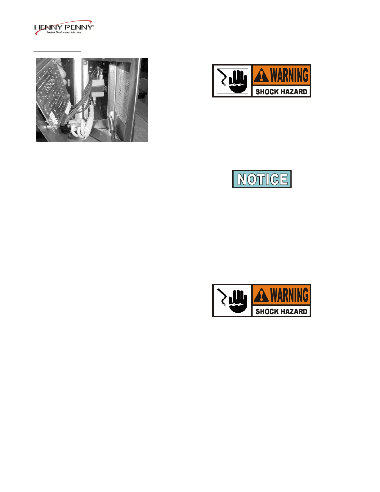
Figure 1-9 2. Remove the two screws on the front of the control
panel and pull out the control panel.
Before pulling control panel out on HC-944s, remove
four screws securing control box (Figure 1-9).
The front relay controls the heat of the left drawer, the
back relay controls the right drawer, and the middle
relays control the middle drawers.
Checkout:
3. With no power (24 volts) going to the relay, 120 volts
should show on the output side of the relay, and 0
volts on the input (24 volts).
To avoid electrical shock, make connections before
applying power, take reading, and remove power
before removing meter leads. The following
checks are performed with the wall circuit breaker
closed and the POWER switch in the ON position.
4. With the component energized, 0 volts should show
on the output side of the relay, and 12 volts on the
input side.
5. If voltage varies from steps 3 and 4, remove power to
unit pull input wires from relay and place leads of
meter onto input wires. Reapply power to unit.
When unit is running, if the input wires to relay
shows 5vdc, the relay is faulty.
1-6 203
Page 11
Model MP-941/942/943/944
1-8. RELAYS (Continued) Replacement:
6. Remove power supplied to unit.
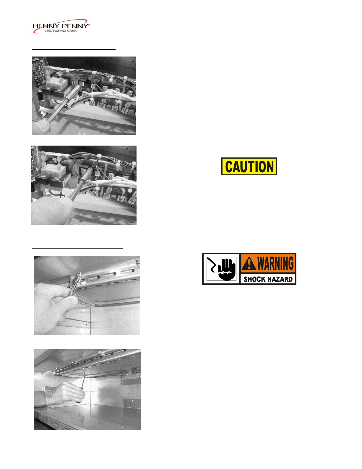
7. Label and remove wires from the appropriate relay
(Figure 1-10).
8. Using a Phillips head screwdriver, remove the screws
securing the relay and remove the relay from the unit
(Figure 1-11).
Figure 1-10 9. Coat the back of the relay with the thermal joint
compound and install new relay.
Failure to use the thermal joint compound will
shorten the life of the relay.
10. Replace control panel and unit is now ready for use.
Figure 1-11
1-9. HEATING ELEMENTS 1. Disconnect the electrical supply to the cabinet.
To avoid electrical shock or property damage,
move the POWER switch to OFF and disconnect
main circuit breaker, or unplug cord at wall
receptacle.
2. Remove the drawer from the appropriate liner.
Figure 1-12 3. Using a 3/8” socket, remove the four acorn nuts
securing the front of the bracket (Figure 1-12).
4. Using a Phillips head screwdriver, remove the six
screws securing the bracket and remove the bracket
(Figure 1-13).
Figure 1-13
1-7 103
Page 12
Model MP-941/942/943/944
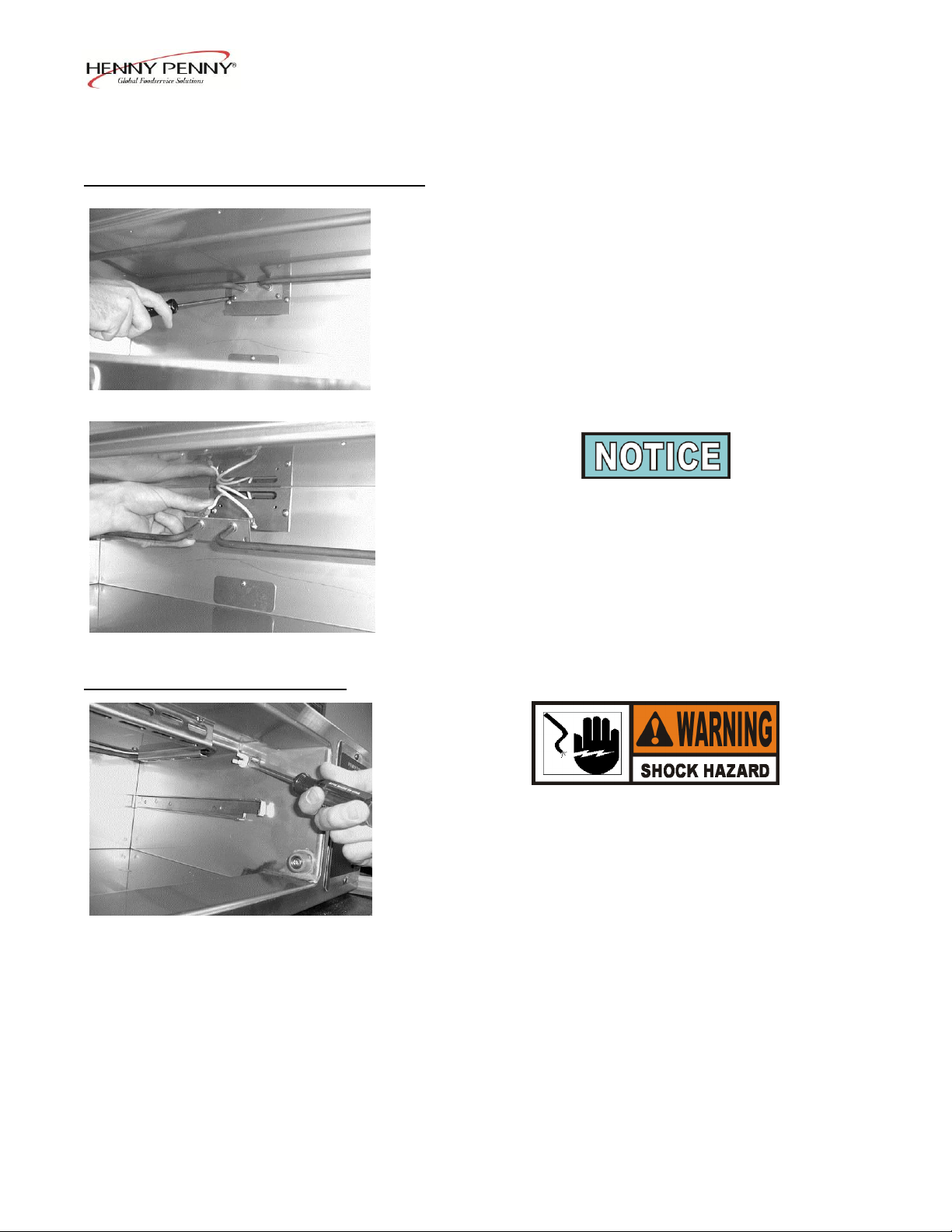
1-9. HEATING ELEMENTS (Continued) 5. Using a Phillips head screwdriver, remove the two
screws securing the element to the back of the liner
(Figure 1-14).
6. Pull the element out towards you until the terminals
are exposed.
Figure 1-14 7. Pull the wires off of the terminals and remove
element from the unit (Figure 1-15).
To check the elements, they should show an ohm
reading of 30 ohms, after the wires have been
removed.
8. Install new element in reverse order.
Figure 1-15
1-10. TEMPERATURE PROBE 1. Disconnect the electrical supply to the cabinet.
To avoid electrical shock or property damage,
move the POWER switch to OFF and disconnect
main circuit breaker, or unplug cord at wall
receptacle.
2. Remove the appropriate drawer.
Figure 1-16
3. Using a flat blade screwdriver, pry the rubber strain
relief from the liner (Figure 1-16).
4. Pull the probe wires out of the unit far enough to
access the connector incased in a protective cover.
5. Cut the wire ties on the ends of cover and slide the
protective cover up and out of the way.
1-8 203
Page 13
Model MP-941/942/943/944
1-10. TEMPERATURE PROBE 6. Disconnect the wires at the connector.
(Continued)
7. Reconnect the new probe assembly to the unit and
pull protective cover back over the connector, then
secure with wire ties.
8. Thread the wire back through the hole and push the
strain relief back into the liner (Figure 1-17).
9. Place drawer back into unit and the unit is now ready.
for use.
Figure 1-17
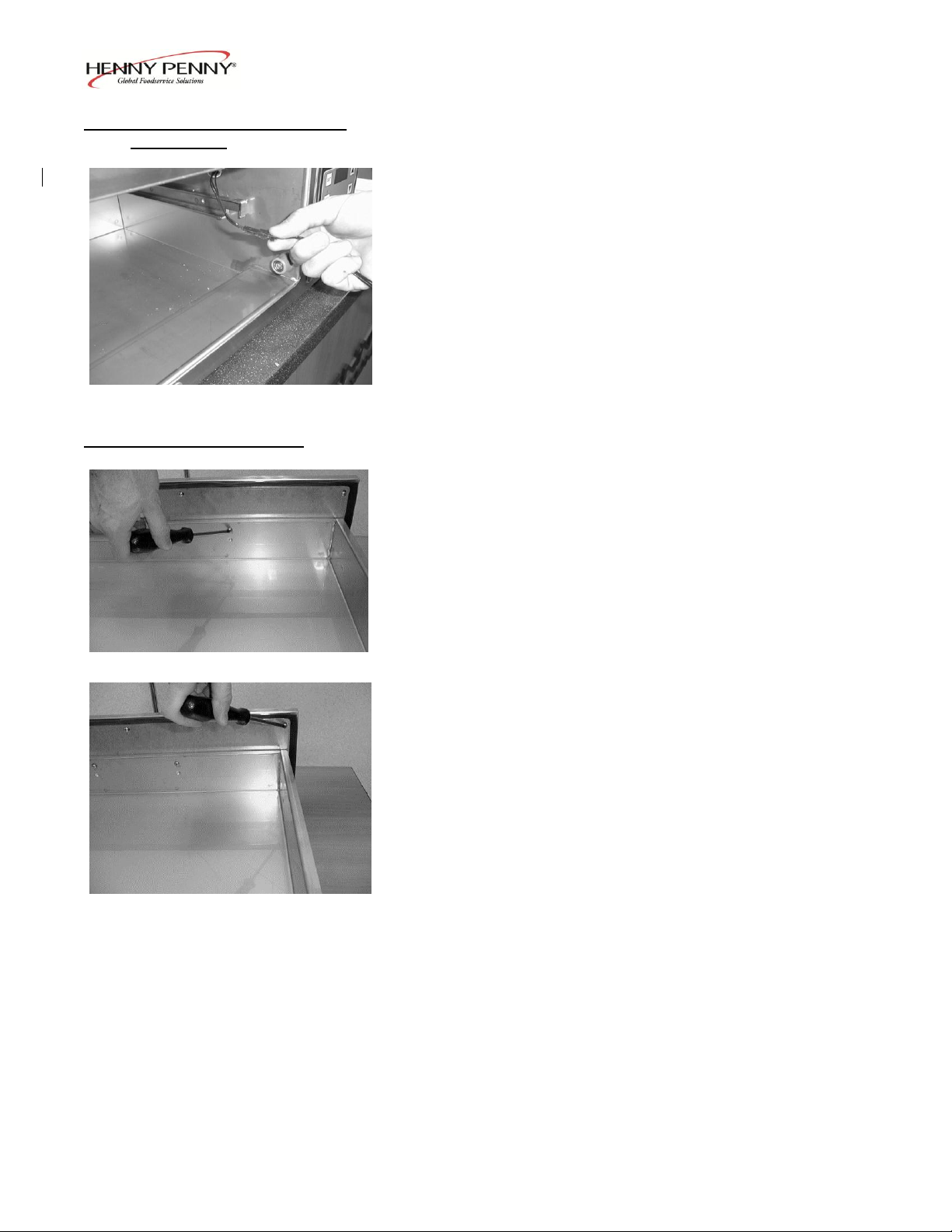
1-11. DRAWER GASKET 1. Remove the drawer from the unit.
2. Using a Phillips head screwdriver, remove the drawer
handle by removing the two screws fastening the
handle to the drawer (Figure 1-18).
Figure 1-18
3. Using a Phillips head screwdriver, remove the six
screws that secure the backing plate and gasket to the
drawer front (Figure 1-19).
4. Separate the drawer frame from the drawer front.
5. Remove the gasket from the drawer front.
Figure 1-19 6. Reassemble the drawer frame and drawer front in
reverse order of disassembly. Make sure the two
drawer-handle spacers, between the drawer front and
backing plate, remain centered over the holes so that
the handle screws pass through the spacers.
103 1-9
Page 14
Model MP-941/942/943/944
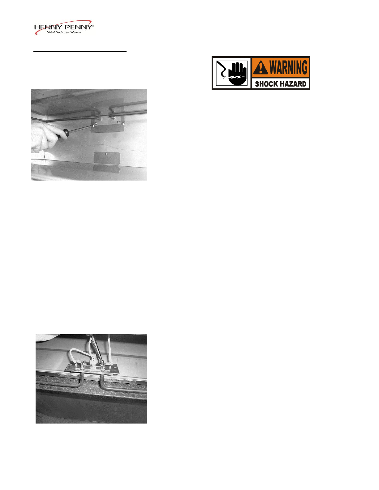
1-12. HIGH LIMIT (335 F) 1. Disconnect the electrical supply to the cabinet.
To avoid electrical shock or property damage,
move the POWER switch to OFF and disconnect
main circuit breaker, or unplug cord at wall
receptacle.
2. Remove the drawer from the appropriate liner.
3. Using a 3/8” socket, remove the four acorn nuts
securing the front of the bracket
(Figure 1-12).
Figure 1-20 4. Using a Phillips head screwdriver, remove the six
screws securing the bracket and remove the bracket
(Figure 1-13).
5. Using a Phillips head screwdriver, remove the two
screws securing the plate to the back of the liner
(Figure 1-20).
6. Pull the element out towards you until the terminals
are exposed.
7. Label and pull the wires off of the terminals and high
limit remove element from the unit.
8. Once the wires have been removed from the high
limit, check for continuity across the terminals. The
circuit should be closed if the high limit is good, if it
shows open, continue on to step 9 and replace high
limit.
9. Using a 5/16” socket, remove the nuts securing the
high limit and remove the high limit from the unit
(Figure 1-21).
10. Install new high limit in reverse order.
Figure 1-21
1-10 203
Page 15
Model MP-941/942/943/944
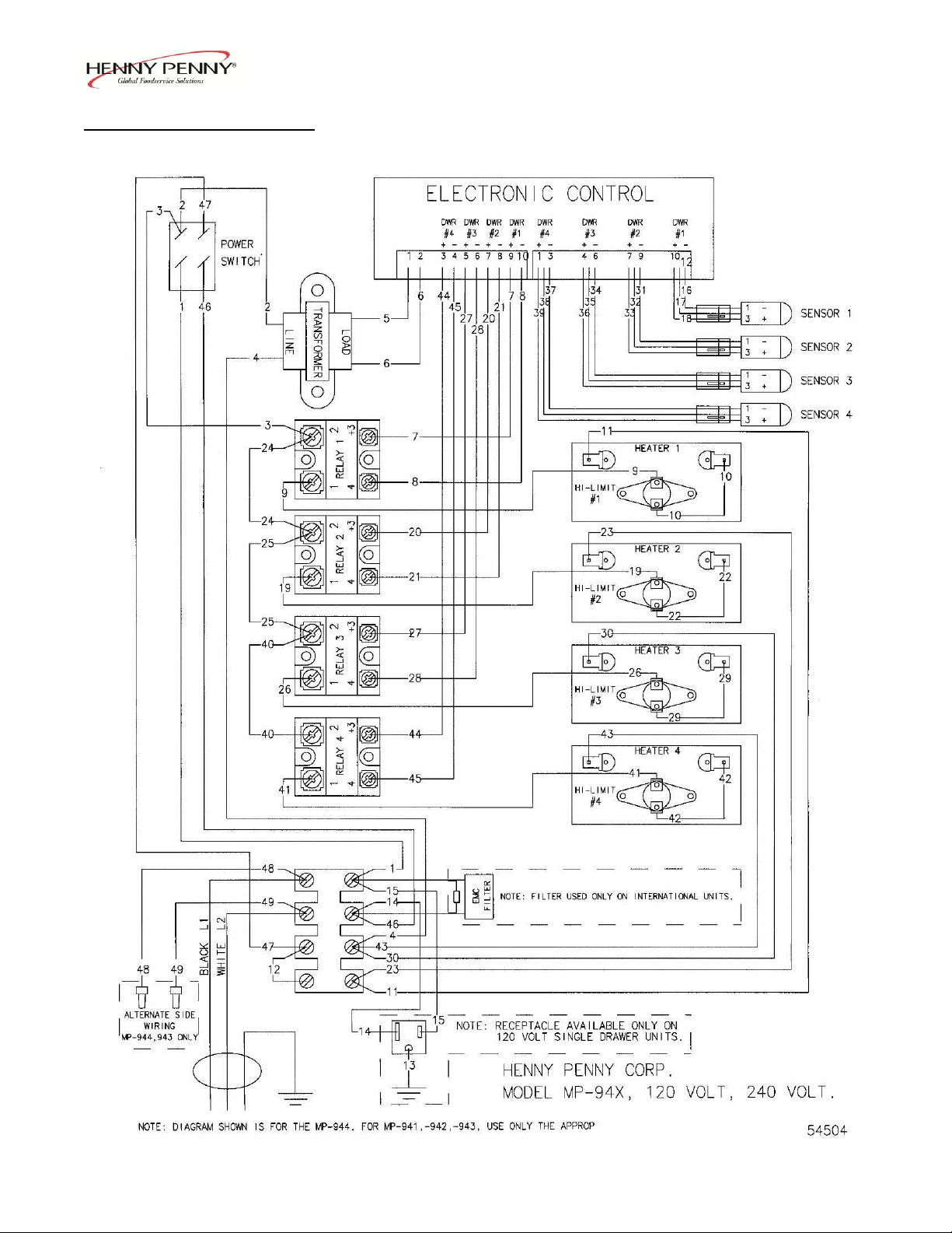
1-13. WIRING DIAGRAMS
103 1-11
Page 16
Model MP-941/942/943/944
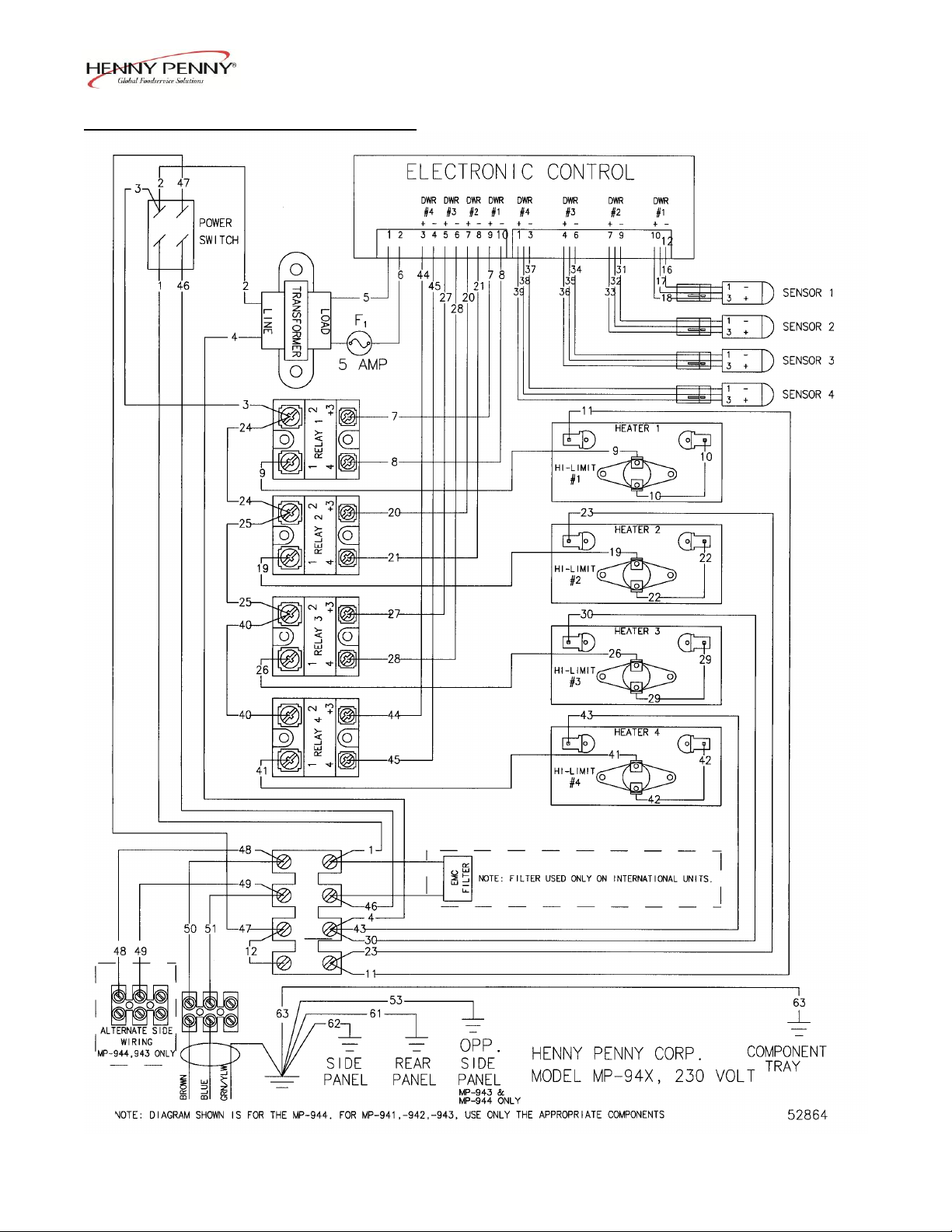
1-13. WIRING DIAGRAMS (Continued)
1-12 103
Page 17

Model MP-941/942/943/944
Page 18
Model MP-941/942/943/944
LIMITED WARRANTY FOR HENNY PENNY EQUIPMENT
Subject to the following conditions, Henny Penny Corporation makes the following limited warranties to the original
purchaser only for Henny Penny appliances and replacement parts:
NEW EQUIPMENT: Any part of a new appliance, except baskets, lamps, and fuses, which proves to be defective
in material or workmanship within two (2) years from date of original installation, will be repaired or replaced
without charge F.O.B. factory, Eaton, Ohio, or F.O.B. authorized distributor. Baskets will be repaired or replaced
for ninety (90) days from date of original installation. Lamps and fuses are not covered under this Limited
Warranty. To validate this warranty, the registration card for the appliance must be mailed to Henny Penny within
ten (10) days after installation.
FILTER SYSTEM: Failure of any parts within a fryer filter system caused by the use of the non-OEM filters or
other unapproved filters is not covered under this Limited Warranty.
REPLACEMENT PARTS: Any appliance replacement part, except lamps and fuses, which proves to be defective
in material or workmanship within ninety (90) days from date of original installation will be repaired or replaced
without charge F.O.B. factory, Eaton, Ohio, or F.O.B. authorized distributor.
The warranty for new equipment covers the repair or replacement of the defective part and includes labor charges and
maximum mileage charges of 200 miles round trip for a period of one (1) year from the date of original installation.
The warranty for replacement parts covers only the repair or replacement of the defective part and does not include any
labor charges for the removal and installation of any parts, travel, or other expenses incidental to the repair or replacement of
a part.
EXTENDED FRYPOT WARRANTY: Henny Penny will replace any frypot that fails due to manufacturing or
workmanship issues for a period of up to seven (7) years from date of manufacture. This warranty shall not cover any frypot
that fails due to any misuse or abuse, such as heating of the frypot without shortening.
0 TO 3 YEARS: During this time, any frypot that fails due to manufacturing or workmanship issues
will be replaced at no charge for parts, labor, or freight. Henny Penny will either install a new frypot at no
cost or provide a new or reconditioned replacement fryer at no cost.
3 TO 7 YEARS: During this time, any frypot that fails due to manufacturing or workmanship issues
will be replaced at no charge for the frypot only. Any freight charges and labor costs to install the new
frypot as well as the cost of any other parts replaced, such as insulation, thermal sensors, high limits,
fittings, and hardware, will be the responsibility of the owner.
Any claim must be presented to either Henny Penny or the distributor from whom the appliance was purchased. No
allowance will be granted for repairs made by anyone else without Henny Penny’s written consent. If damage occurs during
shipping, notify the sender at once so that a claim may be filed.
THE ABOVE LIMITED WARRANTY SETS FORTH THE SOLE REMEDY AGAINST HENNY PENNY FOR ANY
BREACH OF WARRANTY OR OTHER TERM. BUYER AGREES THAT NO OTHER REMEDY (INCLUDING
CLAIMS FOR ANY INCIDENTAL OR CONSEQUENTIAL DAMAGES) SHALL BE AVAILABLE.
The above limited warranty does not apply (a) to damage resulting from accident, alteration, misuse,
or abuse; (b) if the equipment’s serial number is removed or defaced; or (c) for lamps and fuses. THE
ABOVE LIMITED WARRANTY IS EXPRESSLY IN LIEU OF ALL OTHER WARRANTIES,
EXPRESS OR IMPLIED, INCLUDING MERCHANTABILITY AND FITNESS, AND ALL OTHER
WARRANTIES ARE EXCLUDED. HENNY PENNY NEITHER ASSUMES NOR AUTHORIZES
ANY PERSON TO ASSUME FOR IT ANY OTHER OBLIGATION OR LIABILITY.
Revised 01/01/07
1-14 207
Page 19

Model MP-941/942/943/944
SECTION 2. PARTS INFORMATION
2-1. INTRODUCTION This section identifies and lists the replaceable parts of the
Henny Penny Multipurpose Holding Cabinets.
2-2. GENUINE PARTS Use only genuine Henny Penny parts in your cabinet.
Using a part of lesser quality or substitute design may result
in cabinet damage or personal injury.
2-3. HOW TO ORDER Once the part you want to order has been found in the Parts
List, write down the following information:
1. From the Parts List:
(Sample)
Item Number 1
Part Number 51718
Description Gasket – Drawer
2. From the data plate:
(Sample)
Product Number 05882
Serial Number 0001
Voltage 120V
2-4. PRICES Your independent Henny Penny distributor has a price parts
list and will be glad to inform you of the cost of your parts
order.
2-5. DELIVERY Commonly replaced items are stocked by your independent
Henny Penny distributor and will be sent out when your
order is received. Other parts will be ordered by the
distributor from Henny Penny Corporation. Normally,
these will be sent to your distributor within three working
days.
2-6. WARRANTY All replacement parts (except lamps and fuses) are covered
under warranty for 90 days against manufacturing defects
and workmanship. If damage occurs during shipping,
notify the carrier at once so that a claim may be properly
filed. Refer to warranty on the front of this section for
other rights and limitations.
2.7. RECOMMENDED Recommended replacement parts, stocked by your
SPARE PARTS FOR distributor, are indicated with in the parts lists. Please
DISTRIBUTORS use care when ordering recommended parts, because all
voltages and variations are marked. Distributors should
order parts based upon common voltages and equipment
sold in their territory.
106 2-1
Page 20
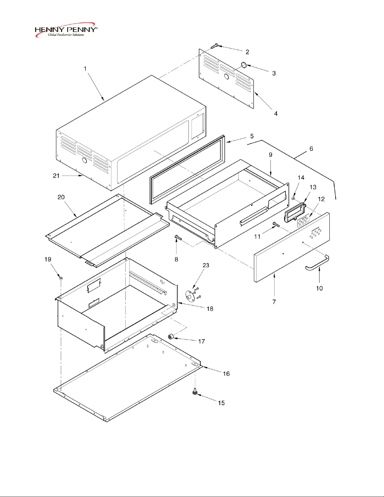
Model MP-941/942/943/944
Figure 2-1. Shell and Drawer
2-2 512
Page 21

Model MP-941/942/943/944
FIG. &
ITEM QTY QTY QTY QTY
NO. PART NO. DESCRIPTION 941 942 943 944
2-1 SHELL AND DRAWER
1 51514 SHELL ASSY. - 941 1 - - 1 52626 SHELL ASSY. - 942 - RH - 1 - 1 52649 SHELL ASSY. - 942 - LH - 1 - 1 52650 SHELL ASSY. - 943 - RH - - 1 1 52651 SHELL ASSY. - 943 - LH - - 1 1 52652 SHELL ASSY. - 944 - RH - - - 1
1 52653 SHELL ASSY. - 944 - LH - - - 1
2 SC01-034 SCREWS 10 10 10 10
3 PL01-014 PLUG - 1 1/16” 2 3 3 1
4 51306 PANEL - ACCESS - RH 1 1 1 4 51912 PANEL - RH - SIDE ACCESS - 944 - - - 1
5 51718 GASKET - DRAWER 1 2 3 4
6 49548 DRAWER ASSY. 1 2 3 4
7 14715 . KIT - DRAWER FRONT ASSY (1 VENT) 1 2 3 4
8 SC02-016 . SCREW, FRONT RETAINING 5 10 15 20
9 49550 . DRAWER WELD ASSY. 1 2 3 4
10 31395 . DRAWER HANDLE 1 2 3 4
11 SC01-144 . SCREW, HANDLE RETAINING 2 4 6 8
12 51497 . SLIDE VENT 1 2 3 4
13 27501 . MOLDED BLOCK - VENT 1 2 3 4
14 NS02-006 . NUT 3 6 9 12
15 26411 FOOT 4 4 5 16 51503 BASE ASSY. - 941 1 - - 16 53639 BASE ASSY. - 942 - RH - 1 - 16 52640 BASE ASSY. - 942 - LH - 1 - 16 52641 BASE ASSY. - 943 - RH - - 1 16 52642 BASE ASSY. - 943 - LH - - 1 -
17 14113 BEARING KIT 1 2 3 4
18 51505 LINER WELD ASSY. 1 2 3 4
19 NS02-002 NUT 4 8 12 16
20 52131 LINER - TOP STUD ASSY. 1 2 3 4
21 51097 PANEL - ACCESS - LH 1 1 1 21 51912 PANEL - ACCESS - LH - - - 1
22* 52701 DECAL - TEMP. CALIBRATION 1 1 1 1
23 14458 KIT – BEARING SUPPORT 2 4 6 8
recommended parts
*not shown
512 2-3
Page 22
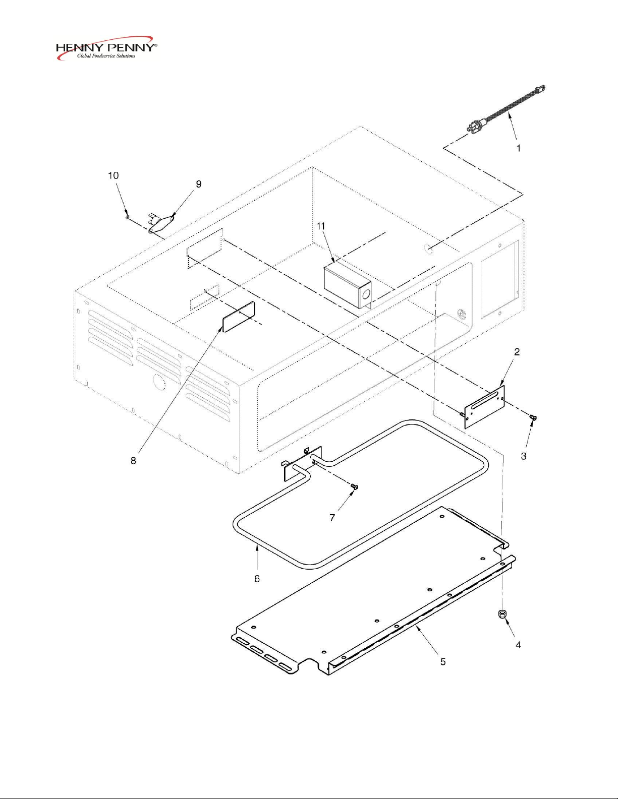
Model MP-941/942/943/944
Figure 2-2. Heater and Cover Plate
2-4 607
Page 23

Model MP-941/942/943/944
FIG. &
ITEM QTY QTY QTY QTY
NO. PART NO. DESCRIPTION 941 942 943 944
2-2 HEATER AND COVER PLATE
1 52100 TEMPERATURE SENSOR ASSY. 1 2 3 4
2 51951 BRACKET – HEATER (BEFORE SN: GA0407031) 1 2 3 4
3 SC01-034 SCREW 2 4 6 8
4 NS03-024 ACORN NUT 3 6 9 12
5 51329 DEFLECTOR – HEAT(BEFORE APRIL 1, 2001) 1 2 3 4
5 70793 DEFLECTOR – HEAT(APRIL 1, 2001 & AFTER) 1 2 3 4
6 51796 HEATER - 475 W. - 120 V. 1 2 3 4
6 51932 HEATER - 475 W. - 240 V. 1 2 3 4
7 SC02-041 SCREW 2 2 2 2
8 51325 PLATE - HEATER COVER 1 2 3 4
9 18201 HIGH LIMIT - 335º F 1 2 3 4
10 NS02-005 NUT 2 2 2 2
11 52237 COVER - TEMP. SENSOR 1 2 3 4
12* 51468 INSULATION - NON-CONTROL SIDE RH 1 1 1 12* 52689 INSULATION - LINER - CONTROL SIDE LH - 1 1 12* 51473 INSULATION - LINER - CONTROL SIDE RH - - - 1
12* 52691 INSULATION - LINER - CONTROL SIDE LH - - - 1
12* 51469 INSULATION - SHELL TOP 1 2 3 4
12* 51470 INSULATION - LINER - BOTTOM 1 2 3 4
12* 51471 INSULATION - LINER - REAR - LOWER 1 2 3 4
12* 51472 INSULATION - LINER - REAR - TOP 1 2 3 4
12* 51474 INSULATION - LINER - TOP 1 2 3 4
12* 52093 INSULATION - LINER - TOP 1 - - 4
12* 51475 INSULATION - CONTROL SIDE RH 1 1 1 12* 52690 INSULATION - LINER - NON-CONTROL
SIDE LH - 1 1 12* 51116 INSULATION - LINER - NON-CONTROL
SIDE RH - - - 1
12* 52692 INSULATION - LINER - NON-CONTROL
SIDE LH - - - 1
recommended parts
*not shown
607 2-5
Page 24
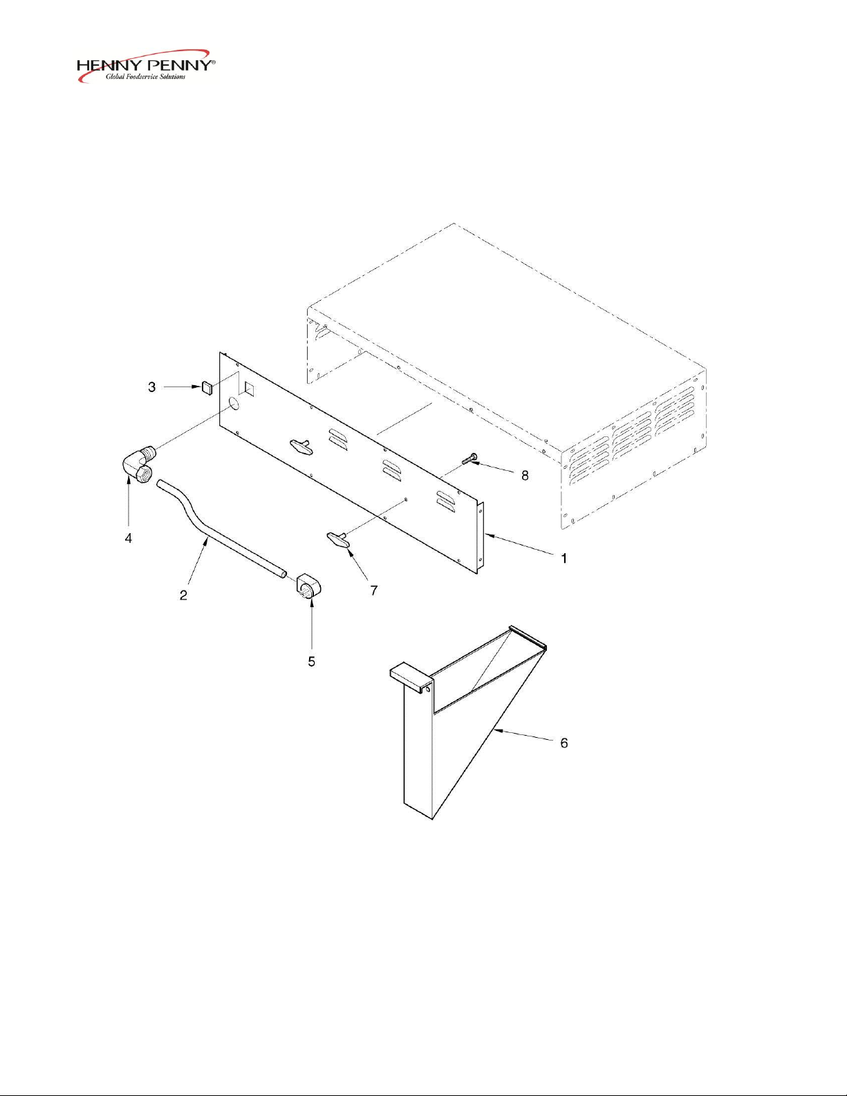
Model MP-941/942/943/944
Figure 2-3. Rear Panel
2-6 204
Page 25

Model MP-941/942/943/944
FIG. &
ITEM QTY QTY QTY QTY
NO. PART NO. DESCRIPTION 941 942 943 944
2-3 REAR PANEL
3 1 51297 REAR ACCESS PANEL - 941 1 - - 3 1 51351 REAR ACCESS PANEL - 942 - 1 - 3 1 51947 REAR ACCESS PANEL - 943 - - 1 3 1 52647 REAR ACCESS PANEL STUD ASSY. - - - 1
3 2 40297 POWER CORD ASSY. 1 1 1 3 2 27555 POWER CORD ASSY. - 944 - - - 1
3 2 63837 POWER CORD ASSY. – CE 1 2 3 4
3 3 MS01-197 RECEPTACLE - NEMA 5-15 R 1 - - 3 4 27639 STRAIN RELIEF 1 1 1 1
3 5 40298 PLUG - ANGLED - 125 V. - 15 AMP 1 1 1 3 5 27692 PLUG - ANGLED - 125 V - 20 AMP - - - 1
3 6 52676 MIDDLE SUPPORT BRACKET - 944 - - - 1
3 7 27645 KNOB - CORD WRAP – 941 (BEFORE 3-6-06) 2 - - 3 8 SC01-172 SCREW (BEFORE 3-6-06) 4 - - -
607 2-7
Page 26
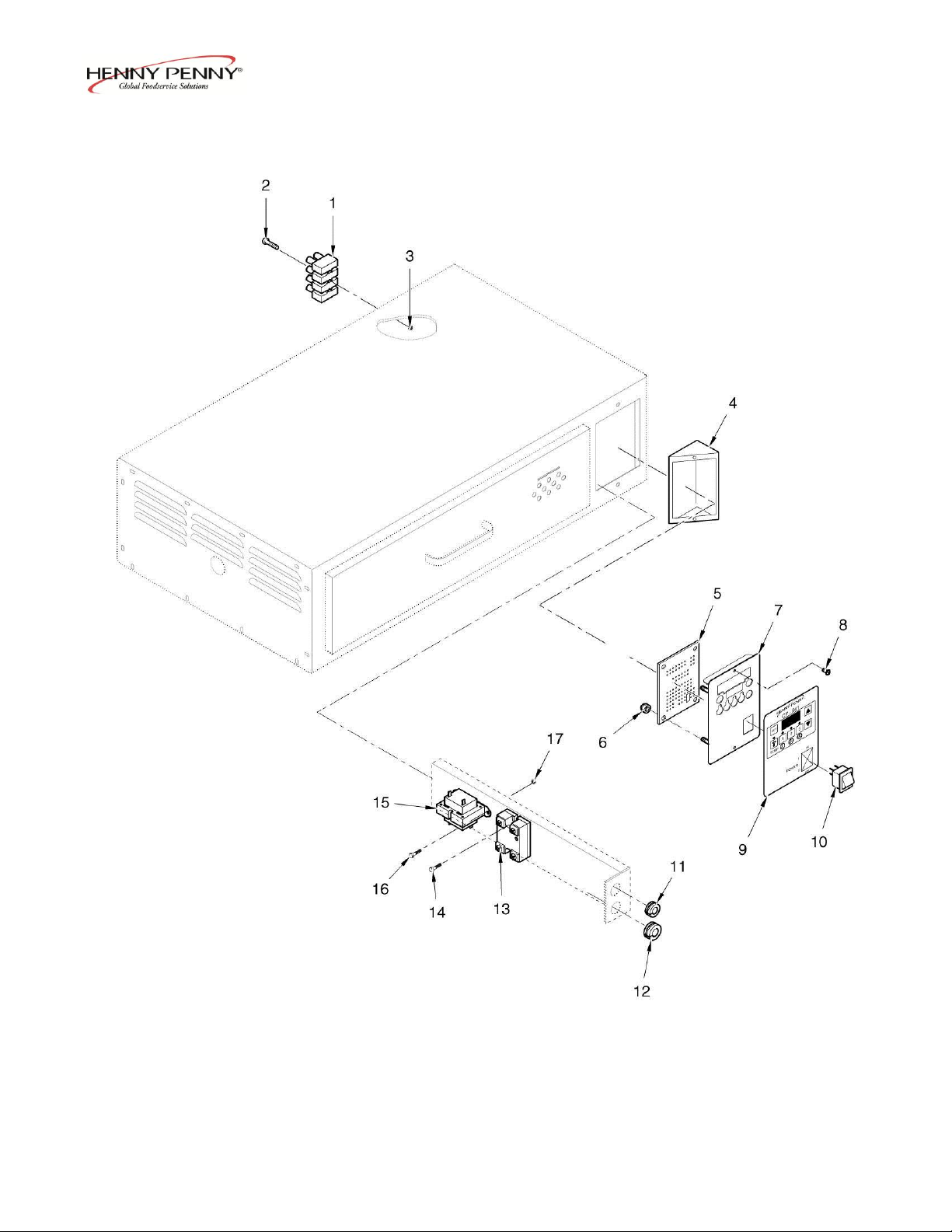
Model MP-941/942/943/944
Figure 2-4. Electrical Controls
2-8 204
Page 27

Model MP-941/942/943/944
FIG. &
ITEM QTY QTY QTY QTY
NO. PART NO. DESCRIPTION 941 942 943 944
2-4 ELECTRICAL CONTROLS
1 33073 TERMINAL BLOCK – 4 POLE 1 1 1 1
2 SC01-053 SCREW 3 3 3 3
3 NS02-007 NUT 3 3 3 3
4 51925 CONTROL BRACKET WELD ASSY. - - - 1
5 52755RB PC BOARD ASSY. – GEN. MKT. 1 1 1 1
5 51102RB PC BOARD ASSY. – WENDY’S 1 1 1 1
6 NS02-005 NUT 4 4 4 4
7 51924 CONTROL PANEL STUD ASSY. - - - 1
7 51545 CONTROL PANEL STUD ASSY. 1 2 3 8 SC04-003 SCREW 2 2 2 2
9 51463 DECAL - CONTROL - 941 - WENDY’S 1 - - 9 52695 DECAL - CONTROL - 941 - GEN. MKT. 1 - - 9 52699 DECAL - CONTROL - 941 - DAIRY QUEEN 1 - - 9 51560 DECAL - CONTROL - 942 - WENDY’S - 1 - 9 52696 DECAL - CONTROL - 942 - GEN. MKT. - 1 - 9 51561 DECAL - CONTROL - 943 - WENDY’S - - 1 9 52697 DECAL - CONTROL - 943 - GEN. MKT. - - 1 9 51464 DECAL - CONTROL - 944 - WENDY’S - - - 1
9 52698 DECAL - CONTROL - 944 - GEN. MKT. - - - 1
10 72277 SWITCH - POWER DPST SPLASH PROOF 1 1 1 1
10 52224 POWER SWITCH – CE 1 1 1 1
11 EF02-072 BUSHING - SPLIT 1 1 1 1
12 EF02-040 BUSHING - SNAP 1 1 1 1
13 40645 RELAY 1 2 3 4
14 SC04-003 SCREW 2 2 2 2
15 28979 TRANSFORMER - 208/240 V. 1 1 1 1
15 30978 TRANSFORMER - 120 V. 1 1 1 1
16 SC01-034 SCREW 2 2 2 2
17 NS02-007 NUT 2 2 2 2
18* 51390 EMC FILTER – CE 1 1 1 1
18* FA53-005 FUSE – CE 1 1 1 1
19* EF02-114 FUSE HOLDER 1 1 1 1
recommended parts
*not shown
607 2-9
Page 28
Model MP-941/942/943/944
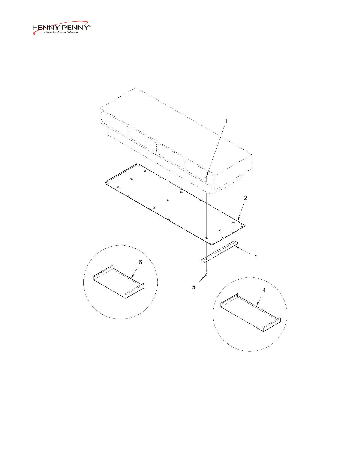
Figure 2-5. Paper Tray
2-10 204
Page 29

Model MP-941/942/943/944
FIG. &
ITEM QTY QTY QTY QTY
NO. PART NO. DESCRIPTION 941 942 943 944
2-5 PAPER TRAY
1 NS-02-007 NUT - - - 12
2 52854 PANEL - BOTTOM ACCESS - - - 1
3 52845 BRACKET – PAPER TRAY - - - 4
4 05940 3 PAPER TRAY – WENDY’S - - - 2
5 SC01-153 SCREW - - - 12
6 05941 2 PAPER TRAY – WENDY’S - - - 2
204 2-11
 Loading...