


Henny Penny
Split Vat & Full Vat
Open Fryers – Gas
Model LVG-202
Model LVG-203
Model LVG-204
TECHNICAL MANUAL


TABLE OF CONTENTS
Section Page
Section 1. TROUBLESHOOTING .............................................................................................. 1-1
1-1 Introduction .................................................................................................... 1-1
1-2 Safety .............................................................................................................. 1-1
1-3 Troubleshooting .............................................................................................. 1-2
1-4 Error Code Table ............................................................................................ 1-7
Section 2. INFO, FILTER & TEMP BUTTON STATS ............................................................... 2-1
2-1 INFO Button Stats .......................................................................................... 2-1
2-2 FILTER Button Stats ...................................................................................... 2-1
2-3 TEMP Button Stats ......................................................................................... 2-1
2-4 HP Info Mode ................................................................................................. 2-2
Section 3. LEVEL 1 PROGRAMMING ...................................................................................... 3-1
3-1 Modifying Product Settings ........................................................................... 3-1
3-2 AIF Clock ....................................................................................................... 3-3
3-3 Deep Clean Mode ........................................................................................... 3-4
3-4 Fryer Setup ..................................................................................................... 3-5
Section 4. LEVEL 2 PROGRAMMING ...................................................................................... 4-1
4-1 Advanced Product Settings ............................................................................ 4-1
4-2 E-Log (error code log) .................................................................................... 4-2
4-3 Passwords ....................................................................................................... 4-3
4-4 Alert Tone (and volume) ................................................................................ 4-3
4-5 Filter After ...................................................................................................... 4-4
4-6 Filter Time ...................................................................................................... 4-4
Section 5. LEVEL 3 PROGRAMMING ...................................................................................... 5-1
5-1 Additional Advanced Product Settings .......................................................... 5-1
5-2 Special Programming ..................................................................................... 5-2
5-3 Clock Set ........................................................................................................ 5-7
5-4 Data Comm & Heat Control ........................................................................... 5-7
5-5 Tech Mode ...................................................................................................... 5-8
5-6 Stats Mode ...................................................................................................... 5-13
Section 6. INFORMATION MODE ............................................................................................. 6-1
6-1 Info Mode ....................................................................................................... 6-1
Section 7. MAINTENANCE SECTION ...................................................................................... 7-1
7-1 Preventive Maintenance ................................................................................. 7-1
7-2 Maintenance Hints .......................................................................................... 7-1
7-3 Complete Control Replacement ..................................................................... 7-2
7-4 Power Switch Replacement ............................................................................ 7-2
7-5 Burner Tube Removal .................................................................................... 7-3
7-6 Pilot Replacement .......................................................................................... 7-3

Section 7. MAINTENANCE SECTION (Continued)
7-7 High Limit Thermocouple .............................................................................. 7-4
7-8 High Limit Control ......................................................................................... 7-5
7-9 Probe Replacement ......................................................................................... 7-6
7-10 Back Shroud Removal .................................................................................... 7-6
7-11 Blower Replacement ...................................................................................... 7-7
7-12 Vacuum Switch Replacement ......................................................................... 7-7
7-13 JIB Pump Replacement .................................................................................. 7-8
7-14 Selector Valve Drive Motor Replacement ...................................................... 7-9
7-15 Gas Valve Replacement .................................................................................. 7-12
Section 8. PARTS SECTION
8-1 Introduction .................................................................................................... 8-1
8-2 Genuine Parts ................................................................................................. 8-1
8-3 When Ordering Parts ...................................................................................... 8-1
8-4 Prices .............................................................................................................. 8-1
8-5 Delivery .......................................................................................................... 8-1
8-6 Warranty ......................................................................................................... 8-1
8-7 Recommended Spare Parts for Distributors ................................................... 8-1
Apenndix A A-1 Wiring Diagrams & Scematics ....................................................................... A-1

Technical Data for CE Marked Products
Nominal Heat Input: Natural (I2H) = 19,8, kW (67,560 Btu/h)
(Net) Natural (I2E) = 19.8 kW (67,560 Btu/h)
Natural (I2E+) = 19.8 kW (67,560 Btu/h)
Natural (I2L) = 19.8 kW (67,560 Btu/h)
Natural (I2HS) = 19.8 kW (67,560 Btu/h)
Liquid Propane (I3P) = 19,8, kW (67,560 Btu/h)
Liquid Propane/Butane (I3B/P) = 19,8, kW (67,560 Btu/h)
Nominal Heat Input: Natural (I2H) = 21,98 kW (75,000 Btu/h) (79.13 MJ/h)
(Gross) Natural (I2E) = 21,98 kW (75,000 Btu/h)
Natural (I2E+) = 21,98 kW (75,000 Btu/h)
Natural (I2L) = 21,98 kW (75,000 Btu/h)
Natural (I2HS) = 21,98 kW (75,000 Btu/h)
Liquid Propane (I3P) = 21,98 kW (75,000 Btu/h) (79.13 MJ/h)
Liquid Propane/Butane (I3B/P) = 21,98 kW (75,000 Btu/h) (79.13 MJ/h)
Supply Pressure: Natural (I2H) = 20 mbar (2.0 kPa)
Natural (I2E) = 20 mbar
Natural (I2E+) = 20/25 mbar
Natural (I2L) = 25 mbar
Natural (I2HS) = 25 mbar
Liquid Propane (I3P) = 30/37/50 mbar (3.0/3.7/5.0 kPa)
Liquid Propane/Butane (I3B/P) = 30/50 mbar
Test Point Pressure: Natural (I2H) = 8.7 mbar (.87 kPa)
Natural (I2E) = 8,7 mbar
Natural (I2E+) = N/A
Natural (I2L) = 8.7 mbar
Natural (I2HS) = 8.7 mbar
Liquid Propane (I3P) = 25 mbar (2.5 kPa)
Liquid Propane/Butane (I3B/P) = 30/50 mbar (3.0/5.0 kPa)
Injector Size: Natural (I2H) = 2.08 mm
Natural (I2E) = 2.08 mm
Natural (I2E+) = 1.70 mm
Natural (I2L) = 2.30 mm
Natural (I2HS) = 2.30 mm
Liquid Propane/Butane (I3B/P) = 1.30 mm
Liquid Propane (I3P) *30 mbar = 1.18 mm
Liquid Propane (I3P) *50 mbar = 1.04 mm
This appliance must be installed in accordance with the manufacturer’s instructions and the regulations
in force and only used in a suitable ventilated location. Read the instructions fully before installing or
using the appliance.
Noise generated from this equipment is less than 70 dB(A)
SECTION 1. TROUBLESHOOTING
Model LVG-202, 203, 204
1-1. INTRODUCTION
1-2. SAFETY
This section provides troubleshooting information in the
form of an easy to read table.
If a problem occurs during the rst operation of a new fryer,
recheck the Installation Section of the Operator’s Manual.
Before troubleshooting, always recheck the Operation
Section of the Operator’s Manual.
Where information is of particular importance or is safety
related, the words DANGER, WARNING, CAUTION, or
NOTE are used. Their usage is described on the next page:
SAFETY ALERT SYMBOL is used with DANGER,
WARNING or CAUTION which indicates a personal
injury type hazard.
NOTICE is used to highlight especially important
information.
CAUTION used without the safety alert symbol indicates a potentially hazardous situation which, if not
avoided, may result in property damage.
CAUTION used wih the safety alert symbol indicates a
potentially hazardous situation which, if not avoided,
could result in minor or moderate injury.
WARNING indicates a potentially hazardous situation which, if not avoided, could result in death or
serious injury.
DANGER INDICATES AN IMMINENTLY HAZARDOUS SITUATION WHICH, IF NOT AVOIDED, WILL RESULT IN DEATH OR SERIOUS
INJURY.
Aug. 2012
1-1

Model LVG-202, 203, 204
1-3. TROUBLESHOOTING To isolate a malfunction, proceed as follows:
1. Clearly dene the problem (or symptom) and when it
occurs.
2. Locate the problem in the Troubleshooting table.
3. Review all possible causes. Then, one-at-a-time work
through the list of corrections until the problem is solved.
4. Refer to the maintenance procedures in the Maintenance
Section to safely and properly make the checkout and
repair needed.
If maintenance procedures are not followed correctly,
injuries and/or property damage could result.
Aug. 2012
1-2

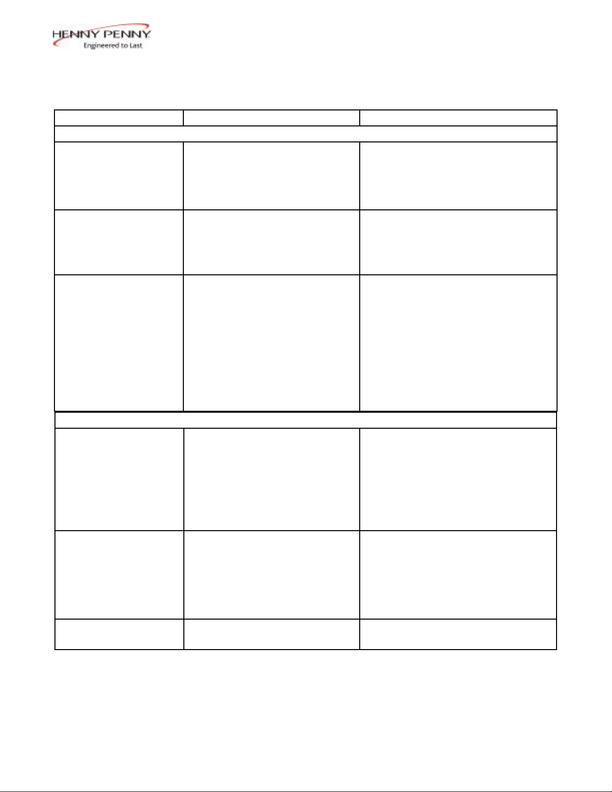
Problem Cause Correction
With power switch in ON position,
the fryer is completely inoperative
(NO POWER)
HEATING OF SHORTENING SECTION
Oil will not heat but lights
are on
No Heat error “E-22”
• Blown fuse or tripped
• Faulty power switch.
• Faulty cord and plug
• Faulty drain switch
• Faulty PC Board
• High limit control switch
tripped
POWER SECTION
• Open circuit
“E-10”
Model LVG-202, 203, 204
• Check to see that unit is plugged in
• Check the breaker or fuse at supply
box
• Check voltage at wall receptacle
• Check MAIN POWERswitch; replace if defective
• Check cord and plug
• Reset transformer circuit breaker
• Reset breaker or replace fuse circuit
breaker at supply box or control panel
• Check power switch
• Check cord and plug
• Check power at receptacle
• Check drain switch
• Check control panel per maintenance
section and replace as needed
• Allow fryer to cool for 15-20
minutes; reset high limit by
pressing down & releasing raised
side of the switch for the vat that is
not operating; a single reset switch
is found behind the door of each
well; if high limit does not reset,
high limit must be replaced
Aug. 2012
1-3
Problem Cause Correction
Oil will not heat (continued)
HEATING OF SHORTENING SECTION (Continued)
• Drain valve open
• Faulty temperature probe
• Faulty gas valve
• Close drain valve
• Replace temerature probe
• Check gas valve
Model LVG-202, 203, 204
Oil heating too slow • Low gas pressure
• Wire(s) loose
• Burnt or charred wire
connection
Oil overheating • Programming wrong
• Faulty PC board
• Faulty temperature probe
• Faulty gas valve
OIL LEVEL SECTION
Oil foaming or boiling
over vat
• Water in oil
• Improper or bad oil
• Improper ltering
• Cold zone (bottom of vats) full
of crumbs
• Improper rinsing after cleaning
the fryer
Oil will not drain from vat
• Drain valve clogged with
crumbs
• Faulty actuator
• Oil channel clogged
Oil leaking through drain
valve
• Obstruction in drain
• Faulty drain valve
• Have gas pressure checked
• Tighten
• Replace wire and clean connections
• Check Temperature setting in the
program mode
• Replacecontrol board if heat
indicator stays on past ready
temperature
• Check probe calibration and
replace if temperature is off ± 5
degrees
• Check gas calve
• At end of a Cook Cycle, drain and
clean vat; add fresh oil
• Use recommended oil
• Refer to the procedure on ltering
the oil.
• Open valve. using cleaning brush,
force crumbs through drain valve
• Replace actuator
• Access the clean-out plug on the
sides of the unit (see Oil Channel
Clean-out Section)
• Remove obstruction
• Replace drain valve
Aug. 2012
1-4

Problem Cause Correction
Vat is under-lled
Bubbles in oil during
entire ltering process
OIL LEVEL SECTION (Continued)
• Locations with RTI, the 3-way
valve is stuck open
• Filter pan needs cleaned
• JIB is low or empty
• JIB oil line is clogged or
collapsed
• Quick Disconnect O-ring may
be worn or missing
• Filter pan needs cleaned
• Filter pan not completely
engaged
• Filter pan clogged
• Damaged o-ring on lter line
tube on fryer
Model LVG-202, 203, 204
• The RTI system can be
disconnected until RTI repairs the
valve
• Clean lter pan and change pad
• Fill the JIB
• Check JIB line
• Check JIB Disconnect O-ring
for wear or cracking. Replace if
missing or torn
• Clean lter pan and change pad
• Make sure lter pan return line
is pushed completely into the
receiver on the fryer
• Clean pan and change pad
• Change o-ring
FILTER MOTOR SECTION
Filter motor runs but
pumps oil slowly
Filter motor will not run • Thermal reset button on the rear
• Filter line connections loose
• Drain pan o-rings damaged or
missing
• Filter paper or pad clogged
of the pump motor is tripped
To prevent burns caused by splashing shortening, turn the unit’s
POWER switch to the OFF position
before resetting the lter pump motor’s manual reset
protection device.
• Tighten all lter line connections
• Install new o-rings
• Change lter paper or pad
• Allow time for the motor to cool.
Open front door and using at
least a 12 in. (305 mm) Phillip’s head
screwdriver, press on the thermal reset
button by prying hard between the
button and the door frame until button
clicks
July 2013
1-5

“IS POT FILLED” lter
error prompt
DISPLAYED PROMPT SECTION
• All oil did not completely return
after a lter cycle
• Filter pad clogged
Model LVG-202, 203, 204
• Have manager follow prompts
• Is JIB full? If not, ll JIB
• Replace lter pad/clean pan.
“CHECK PAN” prompt • Filter drain pan missing
• Filter drain pan not completely
engaged
• Filter drain interlock switch not
• engaged
“CHANGE FILTER PAD”
prompt appears
• Filter pad has not been changed
within a 24hr time period; Main
power switch was turned off during
lter pad change
• Drain pan microswitch stuck
• Find pan and install
• Adjust lter drain pan position
• Check drain microswitch
• Replace old lter pad with NEW
lter pad with main power switch
turned on.
• *NOTE* 24/7 store replace lter
twice a day.
• Check drain microswitch
Aug. 2012
1-6

Model LVG-202, 203, 204
1-4. ERROR CODES
In the event of a control system failure, the digital display
shows an error message. The message codes are shown in the
DISPLAY column below. A constant tone is heard when an error code is displayed, and to silence this tone, press any button.
DISPLAY CAUSE CORRECTION
“E-4” Control board overheating Turn switch to OFF position, then turn switch back
to ON; if display shows “E-4”, the control board is
getting too hot; check the louvers on each side of
the unit for obstructions
Oil overheating Turn switch to OFF position, then turn switch back
“E-5”
to ON; if display shows “E-5”, the heating circuits
and temperature probe should be checked
Temperature probe open Turn switch to OFF position, then turn switch back
“E-6A”
to ON; if display shows “E-6A”, the temperature
probe should be checked
Temperature probe shorted checked Turn switch to OFF position, then turn switch back
“E-6B”
to ON; if display shows “E-6B”, temperature probe
should be
“E-10” E-10A- tripped above 300F
E-10B- tripped below 300F
E-10C- tripped while cooking
E-10D- tripped <5min. of Auto Filter
E-10F- tripped during lter cycle
E-10M- tripped during melt mode
Allow fryer to cool for 15-20 minutes; reset high
limit by pressing down & releasing raisedside of
the switch for the vat that is not operating; a single
reset switch is found behind the door of each well;
if high limit does not reset, high limit must be
replaced
E-10Y- tripped <5min of “YES” to
“IS THE POT FULL?” prompt
“E-15”
“E-18-A”
“E-18-B”
“E-18-C”
“E-20-A”
“FAN
SENSOR
STUCK
CLOSED”
Feb. 2013
Drain valve open Clean and/or close sh vat drain valve; if clean and
closed, have drain switch continuity checked
Left level sensor open
Right level sensor open
Both level sensors open
Turn switch to OFF position, then turn switch back
to ON; If display still indicates a failed sensor,
check the connectors at the control board; check
sensor & replace, if necessory
Pressure switch failure/ Wiring
problem
If fan is not running, have pressure switch
checked; should be open circuit, if no air pressure
If fan is running, wiring error
1-7

1-4. ERROR CODES (CONTINUED)
Model LVG-202, 203, 204
“E-20-B”
“NO
DRAFT”
“CHECK
FAN”
“E-20-D”
Pressure Switch failure/ hose loose
Draft Fan failure/ low voltage/ Flue
or hood obstruction
• Failure to ignite/ no ame sense
• Plugged atmospheric
equalization hole in regulator cap
resulting in pilot ame slowly
fading
Press power button to vat off and back on again,
if E-20-B persists, have pressure switch checked;
should be open circuit if no air pressure; make sure
hose is connected to fan and pressure switch
Have draft fan checked; low voltage going to fan
Check the fryer ue and hood system for
obstructions
• Press power button to vat off and back on
again, if E-20-D persists, check gas line
connections; check gas shutoff valve; check
ignition module; check gas valve; check ame
sensor gap; check gas valve, and check ignition
module wiring
• Clear obstruction from hole
“E-21”
“E-22”
“NO
HEAT”
“E-41” ,
“E-46”
“E-47”
“E-48”
“E-54-C”
Slow heat recovery Have a certied service technician check the fryer
for correct gas supply and pressure to the unit;
have the gas valves checked; have unit checked
for loose or burnt wires
Burner not igniting Have gas valve and heat circuit checked
Programming failure Turn switch to OFF, then back to ON; if display
shows any of these error codes, re-initialize the
controls; if error code persists, check control board
and replace as needed
Analog converter chip or 12 volt
supply failure
Turn switch to OFF, then back to ON; if “E-47”
persists, replace the PC board
Input system error Turn switch to OFF, then back to ON; have control
PC board replaced if “E-48” persists
Temperature input error Turn switch to OFF, then back to ON; have control
PC board replaced if “E-54C” persists
July 2013
1-8

1-4. ERROR CODES (CONTINUED)
Model LVG-202, 203, 204
AIF PC board not communicating
with control PC board
“E-60”
Turn switch to OFF, then back to ON; if “E-60”
persists, check 1.5 amp fuse on AIF PC board on
International units only; check connector between
the PC boards; replace AIF PC board or control PC
board if necessary
Communication error -Verify the OQM senser wiring is correct.
“E-62A”
-Replace cable.
-Replace Sensor
“E-62B” Wrong calibration parameter Replace OQM Sensor
“E-62C” Shorted capacitance Replace OQM Sensor
“E-62D” Shorted RTD Replace OQM Sensor
“E-62E” Open RTD Replace OQM Sensor
”E-62F” Open capacitance Replace OQM Sensor
”E-62G”
“E-70-C”
Out of range (TPM value over 35) Replace oil and take a TPM reading, if the error is
still present replace OQM sensor.
Drain valve jumper wire missing or
disconnected
Have the jumper wire checked on the PC board at
drain switch interlock position
Selector Valve not detected Have wiring checked between Selector Valve and
“E-82A”
AIF board
“E-82B”
Selector Valve failed Have the “Home” switch on Selector Valve
checked
Selector Valve failed Have wiring checked between the “Home” &
“E-82C”
“Position” encoder and the Selector Valve; Have
Selector Valve Motor checked; Have drive chain
checked
“E-82-D”
“E-83”
“PRES-
Selector Valve failed Have the “Home” switch and the “Position” switch
on Selector Valve checked
Pressure Trasducer senses too high
pressure in AIF system
Check AIF system or the RTI quick-disconnect;
See details below;
SURE ”
“TOO
HIGH”
“E-83-A” Pressure too high Check AIF system in Vat #1
“E-83-B” Pressure too high Check AIF system in Vat #2
“E-83-C” Pressure too high Check AIF system in Vat #3
“E-83-D” Pressure too high Check AIF system in Vat #4
“E-83-E” Pressure too high Check AIF system in Vat #5
“E-83-J”
“E-83-R”
RTI “JIB FILL” switch ON when
pressure too high
RTI “DISPOSE” switch ON when
pressure too high
Check JIB ll valves
Check RTI quick-disconnect behind fryer; RTI
phone no. if needed: 888-796-4997
“E-83-Z” Unknown source Check RTI system & JIB ll valve
“E-93-A” 24VDC tripped Have drain actuator checked
May 2014
1-9

Model LVG-202, 203, 204
1-10
Model LVG-202, 203, 204
SECTION 2. INFO, FILTER & TEMP BUTTON STATS
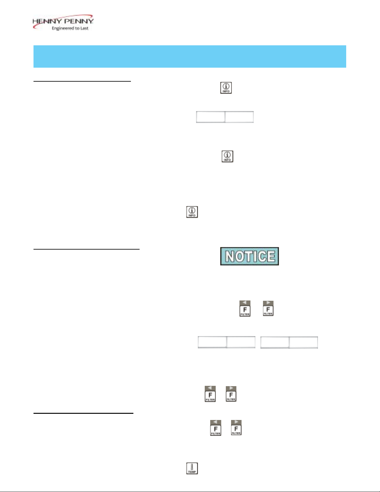
2-1. INFO BUTTON STATS
2-2. FILTER BUTTON STATS
Recovery Information for each Vat/OQM Information
1. Press and release and REC shows in left display and
the recovery time that oil temperature went from 250°F
(121°C) to 300°F (149°C) shows in the right display. For
example, means it took 5 minutes and
30 seconds for the oil temperature to recover to 300°F
(149°C) from 250°F (121°C).
1a. Press and release
reading, date of the last TPM reading, and time stamp of
last TPM reading (only if OQM sensor is installed and
enabled).
Selected Languages
2. Press twice and the primary language shows in the
left display and the secondary language shows in right dis-
play. Press
operation to that language.
REC 5:30
, the display will show the last TPM
ü
button under either language to switch unit
2-3. TEMP BUTTON STATS
If no buttons are pressed within 5 seconds in any of stats
modes, the controls revert back to normal operation.
Cook Cycles Remaining before Filtering
1. Press and release either or and left display
shows “COOKS REMAIN” and right display shows the
number of cook cycles before the next auto lter. For
example,
means after 3 more cook cycles on the left vat, the controls
ask operator if they are ready to lter or not. But, 6 more
cook cycles remain on the right vat.
Time and Date
2. Press either or twice and time-of-day and date
shows in the displays.
Filter Pad Usage
3. Press either or three times and number of hours
the present lter has been used is shown in the displays.
REMA IN
3 6
May 2016
Actual Oil Temperature
1. Press and the actual oil temperature shows in the
display, for each vat.
2-1

Model LVG-202, 203, 204
Set-point Temperature
2. Press twice and SP shows in the display, along with
the set-point (preset) temperature of each vat.
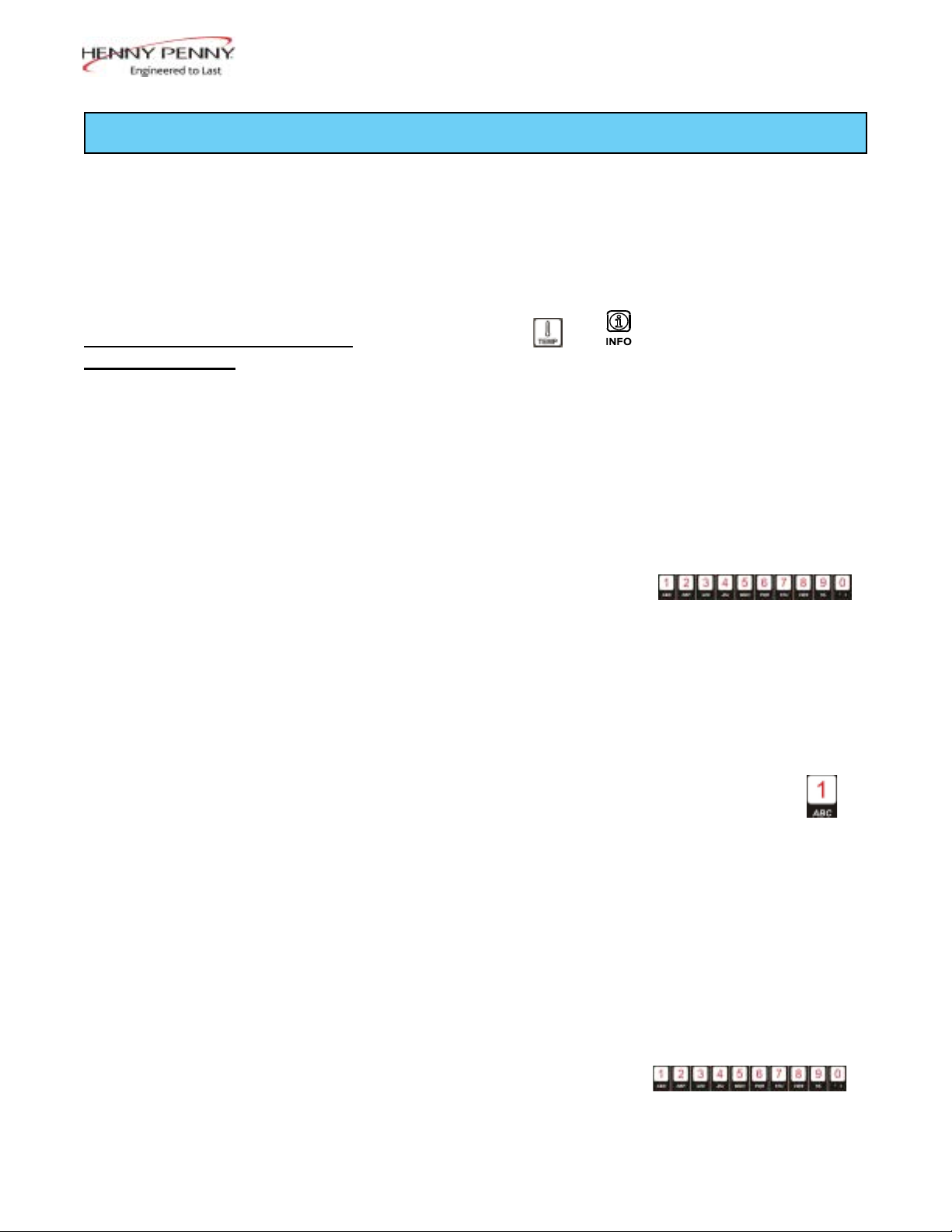
2-4. HP INFO MODE
Cook Cycles Remaining before Filtering
Press and release both and at the same time to
enter HP Info Mode. You can view the following option in HP
Info Mode:
1. E-Log
2. Last Load
3. Daily Stats
4. Review Usage
5. Inputs HDE (to check: high limit, drain switch jumper,
and tilt switch)
6. Outputs S_H (saftey contactor / heat contactor)
7. Oil Temperature
8. CPU Temp
9. Communication OQM Sensor
10. Analog
11. Activity Log
12. Oil Levels (see if low level sensing temperature difference
between probes).
13. Pumps and Valves
14. AIF Info (check for drain pan recognition: Left F button
1X and down arrow 2X.
15. Print Report to USB
16. Remove USB
17. Oil Quality Support
a. Software Version (SVN); hardware (HVN)
b. Serial Number
c. RTC Date
d. RTC Time
e. Vat-1
f. Vat-2
g. Vat-3
h. Vat-4
i. Vat-5
j. Vat-6
k. Vat-7
l. Vat-8
May 2016
2-2
SECTION 3. LEVEL 1 PROGRAMMING
Level 1 contains the following:
• Modify product settings
• Set the AIF clock for products
• Perform the Deep Clean procedure
• Fryer Setup Mode
Model LVG-202, 203, 204
3-1. MODIFYING PRODUCT
SETTINGS
1. Press and hold and buttons until LEVEL - 1
shows in the display, followed by ENTER CODE.
2. Enter code 1, 2, 3, 4 (rst 4 product buttons).
“PRODUCT” and “SELECTN” show in the displays.
3. Press right √ button and ‘SELECT PRODUCT’ and “-P 1-”
(ex: NUGGETS) show in the displays.
Change Product Names
4. Use the ◄ and ► buttons to scroll through 40 products,
or press desired product button
5. Press right √ button and the product (ex: NUGGETS)
shows in left display and “MODIFY”, and “YES NO”
shows in right display. Press √ button to change this
product, or press the X button to choose another product.
6. If √ button was pressed, press and release a product button
and the ashing letter changes to the rst letter under the
product button that was pressed. For example, if
pressed, the ashing letter changes to an “A”.
Aug. 2012
Press same button again and the ashing letter changes to a
“B”. Press it again and the ashing letter changes to a “C”.
Once desired letter shows in the display, press ► button
to continue to the next letter and repeat the procedure.
Press and hold the right X button to exit Program Mode, or
press ▼ button to continue on to “1. COOK TIME”.
To Change Times and Temperatures
7. Press ▼ button until “COOK TIME” shows in display,
and then use product buttons
to change the time in minutes and seconds, to a maximum
of 59:59.
3-1
Model LVG-202, 203, 204
3-1. MODIFYING PRODUCT
SETTINGS (CONTINUED)
8. Press and release▼ button and “TEMP” shows in the dis-
play, along with the preset temperature on the right side of
the display.
Press the product buttons
to change the temperature. The temperature range is 190°F
(88°C) to 380°F (193°C).
Cook ID Change
9. Press ▼ button until “COOK ID” shows in the display
along with the product ID. For example, NUG would be
the ID for nuggets. Use the product buttons to change the
ID, following the same procedure as Step 6 above.
Alarms (Duty 1 & 2)
10. Press ▼ button until “DUTY 1” shows in left display,
and an alarm time in the right display. Press the product
buttons to set an alarm.
Ex., If a Cook Cycle was set at 3 minutes, and an alarm
was to go off after 30 seconds into the Cook Cycle, “0:30”
would be set in the display at this time. When the timer
counts down to 2:30 the alarm sounds.
After alarm time is set, press ▼ button and “DUTY 2”
shows in display, and a second alarm can be programmed.
Quality Timer
11. Press ▼ button until QUAL TMR shows in display along
with preset holding time. Press product buttons to adjust
hold time (2 hrs., 59 min. max.).
AIF Disable
12. Press ▼ button until “AIF DISABLE” shows in display
along with “YES” or “NO”. Using ◄ and ► buttons
change the display to “YES” if that product is to not be
included in the automatic intermittent ltration operation,
or “NO” if it is to be included.
Assign Button
13. Press ▼ button until “ASSIGN BTN” shows in the display, along with the product (ex: NUGGETS). If this product already has a product button assigned to it, that LED
will be lit. To assign other product buttons to that product,
press and hold the product button for 3 seconds and that
LED stays lit. To remove a product from a button, press
and hold the product button with a lit LED and the LED
goes out.
Aug. 2012
3-2

Model LVG-202, 203, 204
3-2. AIF CLOCK
This feature allows controls to be set for periods of the day that
block the automatic “Filter Now” prompts. For example, the
controls could be set not interrupt with “Filter Now” prompts
during the lunch rush, and during the supper rush. But, if ltering is desired during this time, press and hold a button to
access the lter menu.
Each AIF Blocking period is dened by a start time (a time of
day, XX:XX A, etc) and a duration in minutes.
Weekdays M-F are all grouped together. Up to four different
AIF blocking periods may be programmed throughout the day
for Monday - Friday. (All days share the same settings.)
A separate set of four blocking periods may be programmed
for Saturdays, and a nal set of four blocking periods may be
programmed for Sundays.
1. Press and hold and buttons until LEVEL - 1
shows in the display, followed by ENTER CODE.
2. Enter code 1, 2, 3, 4 (rst 4 product buttons). “PRODUCT”
and “SELECTN” show in the displays.
3. Press ▼ button once and “AIF CLOCK” show in
displays.
4. Press √ button and use ◄ and ► buttons to scroll
through “ENABLE” and “DISABLE” and then press √
button again to select one.
5. If “ENABLE” is chosen, then ▲ and ▼ buttons can be
used to scroll through following list of blocking periods:
Left Display Right Display
M-F 1 XX:XX A XX
M-F 2 XX:XX A XX
M-F 3 XX:XX A XX
M-F 4 XX:XX A XX
SAT 1 XX:XX A XX
SAT 2 XX:XX A XX
SAT 3 XX:XX A XX
SAT 4 XX:XX A XX
SUN 1 XX:XX A XX
SUN 2 XX:XX A XX
SUN 3 XX:XX A XX
SUN 4 XX:XX A XX
Aug. 2012
3-3

Model LVG-202, 203, 204
3-2. AIF CLOCK
(CONTINUED)
In 12-hour clock mode, there are three items on each line: the start
time “XX:XX”, the A or P (am/pm) setting, and the “XX” duration.
Use the ◄ and ► buttons to set these items, which ashes when the
item is selected.
To set a new start time setting, use the product buttons,
to enter the new value.
Press the ► button to step over to the AM/PM setting. The A or P
can be toggled by pressing the ‘0’ product button.
Press the ► button again to step over to the duration value (in minutes). Enter a new value using the product buttons,
In 24-hour clock mode, there are only two items on each line: the
time (XX:XX) and the duration (XX). Again, the ◄ and ►
buttons step you between these items.
Press the right-side X button to exit out of AIF Clock programming
mode.
3-3. DEEP CLEAN MODE
This procedure allows a thorough cleaning of the vat by removing caramelized oil from vat. See Section 4-3 in the Operator’s
Manual for complete set of instructions.
Aug. 2012
3-4

Model LVG-202, 203, 204
3-4. FRYER SETUP
This mode has the same settings as seen upon initial start-up of the
fryer.
1. Press and hold and buttons until LEVEL - 1
shows in the display, followed by ENTER CODE.
2. Enter code 1, 2, 3, 4 (rst 4 product buttons). “PRODUCT”
and “SELECTN” show in the displays.
3. Press ▼ button 3 times and “FRYER SETUP” show in
the displays.
4. Press √ button and *SETUP* *MODE* shows in displays,
followed by, “LANGUAGE” on the left display,
“ENGLISH” on the right display.
Use ◄ or ► buttons to change the operation display to,
“FRANCAIS”, “CAN FREN”, “ESPANOL”, “PORTUG”,
“DEUTSCHE”, “SVENSKA”, “РУССКИИ”.
Press ▼ to continue with other set-up items which include:
• ZONE - USA or NON-USA
• TEMP FORMAT - oF or oC
• TIME FORMAT - 12-HR OR 24-HR
• ENTER TIME - Time of day (use product buttons to change)
• ENTER TIME - AM OR PM
• DATE FORMAT - US OR INTERNATIONAL
• ENTER DATE - Today’s date (use product buttons to change)
• FRYER TYPE - GAS or ELEC
• VAT TYPE - FULL OR SPLIT
• DISPOSE BULK OIL - YES/NO (BULK has RTI system)
• SUPPLY BULK OIL - YES/NO (BULK has RTI system)
• DAYLIGHT SAVING TIME - 1.OFF; 2.US (2007 & after);
3.EURO; 4.FSA (US before 2007)
• OIL QUALITY ENABLED (yes or no)
• TPM WARN (value can be set to 0% - 40%)
• TPM MAX (value can be set to 0% - 40%)
Unless otherwise indicated, use ◄ or ► to change settings.
May 2016
3-5


SECTION 4. LEVEL 2 PROGRAMMING
Used to access the following:
• Advanced changes to product settings
• Error code log
• Password programming
• Alert Tone/Volume
• No. of cook cycles before lter is suggested
• Automatic lter time
Model LVG-202, 203, 204
4-1. ADVANCED PRODUCT
SETTINGS
1. Press and hold and buttons until LEVEL - 2
shows in the display, followed by ENTER CODE.
2. Enter code 1, 2, 3, 4 (rst 4 product buttons). “PROD”
and “COMP” show in the displays.
3. Press right √ button and ‘SELECT PRODUCT’ and “-P 1-”
show in the displays.
4. Use the ◄ and ► buttons to scroll through 40 products,
or press the desired product button.
5. Press right √ button and product (ex: NUGGETS) shows in
the left display and “MODIFY” “YES NO” shows in the
right display. Press the √ button to change this product, or
press the X button to choose another product.
>Load Compensation, Load Compensation
Reference, Full Heat, PC Factor<
6. If √ button was pressed, “LD COMP” shows in the display
along with the load compensation value. This automatically adjusts the time to account for the size and temperature
of the cooking load. Press the product buttons
to change this value of 0 to 20.
Aug. 2012
7. Press ▼ button until “LCMP REF” shows in the display
along with the load compensation average temperature.
(if load compensation is set to “OFF”, then “_ _ _” shows
in display and setting cannot be programmed) This is the
average cooking temperature for each product. The timer
speeds up at temperatures above this setting and slows
down at temperatures below this setting. Press the product
buttons to change this value.
4-1
Model LVG-202, 203, 204
4-1. ADVANCED PRODUCT
SETTINGS (CONTINUED)
4-2. E-LOG
(ERROR CODE LOG)
8. Press ▼ button until “FULL HT” shows in display along
with full heat value in seconds, which means heat is on as
soon as a timer button is pressed, for a programmed length
of time. Press product buttons
to change this value of 0 to 90 seconds.
9. Press ▼ button until “PC FACTOR” shows in display
along with the proportional temperature, which helps keep
the oil from over-shooting the setpoint temperature. Press
product buttons to change this
value of 0 to 50 degrees.
• Use ▲ button to go back to previous menu items.
• Press X button when nished with the current product, to
return to the PRODUCT SELECTN step.
• Press X button a second time to exit PROD COMP mode.
1. Press and hold and buttons until LEVEL - 2
shows in the display, followed by ENTER CODE.
2. Enter code 1, 2, 3, 4 (rst 4 product buttons). “PROD”
and “COMP” show in the displays.
3. Press ▼ button and “E-LOG” shows in the display.
4. Press right √ button and “A” plus the present date & time
ashes on the display, along with “*NOW*”.
5. Press ▼ and if an error was recorded, “B” and date, time,
and error code information shows in display. This is the
latest error code that the controls recorded.
6. Press ▼ and the next latest error code information can be
seen. Up to 10 error codes (B to K) can be stored in the
E-Log Section.
Press and hold the right √ button to view a brief description
of the error.
Aug. 2012
4-2
Model LVG-202, 203, 204
4-3. PASSWORDS
The 4-digit passwords can be changed for access to Set-Up,
Usage, Level 1, Level 2, & Get Mgr.)
1. Press and hold and buttons until LEVEL - 2
shows in the display, followed by ENTER CODE.
2. Enter code 1, 2, 3, 4 (rst 4 product buttons). “PROD”
and “COMP” show in the displays.
3. Press ▼ button twice and “PASSWORD” shows in the
display.
4. Press right √ button and “SET UP” shows in display. The
Set up password can be changed at this time, or press ▼
once to change the USAGE password, twice for LEVEL 1
password, 3 times for LEVEL 2 password, or 4 times for
GET MGR password. And then, follow instructions below.
5. If the password for Set Up Mode (for example) is to be
changed, press right √ button and “MODIFY? “YES NO”
shows in the display. Press right √ button to change the
4-digit password for the Set Up Mode, using the product
buttons
4-4. ALERT TONE
(AND VOLUME)
6. Once new password is entered, “CONFIRM PASSWORD”
shows in the display. Press √ button to conrm, or press X
to choose another password.
1. Press and hold and buttons until “LEVEL - 2”
shows in the display, followed by “ENTER CODE”.
2. Enter code 1, 2, 3, 4 (rst 4 product buttons). “PROD”
and “COMP” show in the displays.
3. Press ▼ button 3 times and “ALERT TONE” shows in
the display.
4. Press right √ button and “VOLUME” shows in display,
along with volume value. Use the product buttons
to set volume from 1 (softest) to
10 (loudest).
5. Once volume is set, press √ button and “TONE” shows in
display, along with the tone value. Use the product buttons
to set tone from 50 to 2000 Hz.
Aug. 2012
6. Press X to exit Alert Tone Mode.
4-3

Model LVG-202, 203, 204
4-5. FILTER AFTER
4-6. FILTER TIME
The number of cook cycles between ltering the oil can easily
be programmed for all products.
1. Press and hold and buttons until LEVEL - 2
shows in the display, followed by ENTER CODE.
2. Enter code 1, 2, 3, 4 (rst 4 product buttons). “PROD”
and “COMP” show in the displays.
3. Press ▼ button 4 times and “FILR AFTR” shows in the
left display.
4. Use the product buttons to set the
number to cook cycles between ltering procedures from 0
to 99.
5. Once set, press
The length of time the fryer remains idle between cook cycles
before the controls suggest ltering.
ü
button to conrm.
1. Press and hold and buttons until LEVEL - 2
shows in the display, followed by ENTER CODE.
2. Enter code 1, 2, 3, 4 (rst 4 product buttons). “PROD”
and “COMP” show in the displays.
3. Press ▼button 5 times and “FILR TIME” shows in the
left display (hours:minutes).
4. Use the product buttons to set a
time between cook cycles from 0 to 18:00 hours.
For example, if “5:00” is programmed in the right display,
if the vat was not used for 5 hours after a cook cycle, the
controls would display “FILR NOW?” “YES NO”.
5. Once set, press übutton to conrm.
Aug. 2012
4-4
 Loading...