

Henny Penny LVE-202, LVE-203, LVE-103, LVE-104 Operation Manual
OPERATION
SPLIT/FULL VAT OPEN FRYER (Electric)
MANUAL
MODEL
LVE-202
LVE-203
LVE-204
REGISTER WARRANTY ONLINE AT WWW.HENNYPENNY.COM

Compliance Information
These are the original version controlled Henny Penny instructions for Low oil Volume Electric (L VE)
model 20 number of vats 2 (LVE-202/203/204). Read these instructions completely prior to installation
and operation of this appliance to ensure compliance to all required installation, operation and safety
standards. Read and obey all safety messages to avoid damage to the appliance and personal injury . This
appliance is intended for commercial use in kitchens of restraunts, bakeries, hospitals, etc. but not for the
continuous mass production of food such as in a factory setting. This fryer must be installed and used
in a way that water does not contact the oil which can cause splashing and boiling over of oil and steam
leading to personal injury; excludes normal product moisture. Proper daily , weekly, monthly, quarterly and
yearly maintenance must be performed on this appliance to ensure safe and continuous operation. Proper
maintenance also increases the usable life of the appliance and oil, which reduces lifetime operating costs.
Additionally, old oil increases the possibility of surge boiling and re due to the reduced ash point of the
oil. This appliance must never be cleaned with a water jet or steam cleaning tool. Cleaning brushes are
shipped with the appliance and proper cleaning instructions are included in this manual.

Model LVE-202, 203, 204
TABLE OF CONTENTS
Section Page
Section 1. INTRODUCTION ..............................................................................1-1
1-1 Introduction ..............................................................................1-1
1-2 Proper Care ...............................................................................1-1
1-3 Assistance .................................................................................1-1
1-4 Safety ........................................................................................1-2
Section 2. INSTALLATION................................................................................ 2-1
2-1 Introduction ..............................................................................2-1
2-2 Unpacking .................................................................................2-1
2-3 Selecting the Fryer Location .....................................................2-2
2-4 Leveling the Fryer ....................................................................2-2
2-5 Ventilation of Fryer ...................................................................2-3
2-6 Adjusting Height of Top Cap ....................................................2-3
2-7 Removal of Top Cap .................................................................2-3
2-8 Electrical Requirements ...........................................................2-4
2-9 Dimensions ...............................................................................2-6
2-10 LonWorks Function Conrmation ............................................2-7
Section 3. OPERATION ......................................................................................3-1
3-1 Operating Components .............................................................3-1
3-2 Set-Up Mode .............................................................................3-5
3-3 Filling or Adding Oil ................................................................3-6
3-4 Morning Start-Up Procedures ..................................................3-7
3-5 Cooking with Dedicated Display ..............................................3-8
3-6 Cooking with Multi-Product Display .......................................3-9
3-7 Change from Breakfast to Lunch & Lunch to Breakfast ..........3-9
3-8 Change from Multi-Product Display to Dedicated Display ....3-10
3-9 Change from Dedicated Display to Multi-Product Display ....3-10
3-10 Change from Multi-Product Display to Multi-Product
Display with Different Setpoint Temperatures ........................3-10
3-11 Auto Top-Off ...........................................................................3-11
3-12 Automatic Intermittent Filtration (AIF) ..................................3-12
3-13 Maintenance Filter ...................................................................3-14
3-14 Discarding Oil from Vat Using RTI .........................................3-16
3-15 Discarding Oil from Vat Using Oil Discard Shuttle ................ 3-17
3-16 Discarding Oil from Vat Using Non-RTI (REAR) System .....3-18
3-17 Changing the Filter Pad ...........................................................3-19
3-18 Removing and Cleaning Basket Rest ......................................3-21
3-19 Info Button Stats ......................................................................3-22
3-20 Filter Button Stats ....................................................................3-22
3-21 Temp Button Stats ...................................................................3-22
3-22 Information Mode ....................................................................3-23
Aug. 2012
i

Model LVE-202, 203, 204
TABLE OF CONTENTS (Continued)
Section Page
Section 4. LEVEL 1 PROGRAMMING ............................................................4-1
4-1 Modifying Product Settings ......................................................4-1
4-2 AIF Clock ..................................................................................4-3
4-3 Deep Clean Mode ......................................................................4-4
4-4 Fryer Setup ................................................................................4-8
Section 5. LEVEL 2 PROGRAMMING ............................................................5-1
5-1 Advanced Product Settings .......................................................5-1
5-2 E-Log (error code log) ...............................................................5-2
5-3 Password....................................................................................5-3
5-4 Alert Tone ..................................................................................5-3
5-5 Filter Aftr ...................................................................................5-4
5-6 Filter Time .................................................................................5-4
Section 6. TROUBLESHOOTING ....................................................................6-1
6-1 Troubleshooting Guide ..............................................................6-1
6-2 Error Codes ...............................................................................6-3
Aug. 2012
ii
Model LVE-202, 203, 204
SECTION 1. INTRODUCTION
1-1. INTRODUCTION
1-2. PROPER CARE
The Henny Penny open fryer is a basic unit of food processing
equipment. This unit is used only in institutional and commercial
food service operations.
As of August 16, 2005, the Waste Electrical and Electronic
Equipment directive went into effect for the European Union.
Our products have been evaluated to the WEEE directive. We
have also reviewed our products to determine if they comply with
the Restriction of Hazardous Substances directive (RoHS) and
have redesigned our products as needed in order to comply. To
continue compliance with these directives, this unit must not be
disposed as unsorted municipal waste. For proper disposal, please
contact your nearest Henny Penny distributor.
As in any unit of food service equipment, the Henny Penny open
fryer does require care and maintenance. Requirements for the
maintenance and cleaning are contained in this manual and must
become a regular part of the operation of the unit at all times.
1-3. ASSISTANCE
Should you require outside assistance, call your local independent
distributor in your area, or call Henny Penny Corp. at 1-800-4178405 or 1-937-456-8405.
Aug. 2012
1-1
Model LVE-202, 203, 204
1-4. SAFETY
OR
The Henny Penny open fryer has many safety features
incorporated. However, the only way to ensure a safe operation
is to fully understand the proper installation, operation, and
maintenance procedures. The instructions in this manual have
been prepared to aid you in learning the proper procedures.
Where information is of particular importance or safety related,
the words DANGER, WARNING, CAUTION, and NOTICE are
used. Their usage is described below.
This appliance is not intended for use by persons (including
children) with reduced physical, sensory or mental capabilities, or
lack of experience and knowledge, unless they have been given
supervision or instruction concerning use of the appliance by a
person responsible for their safety
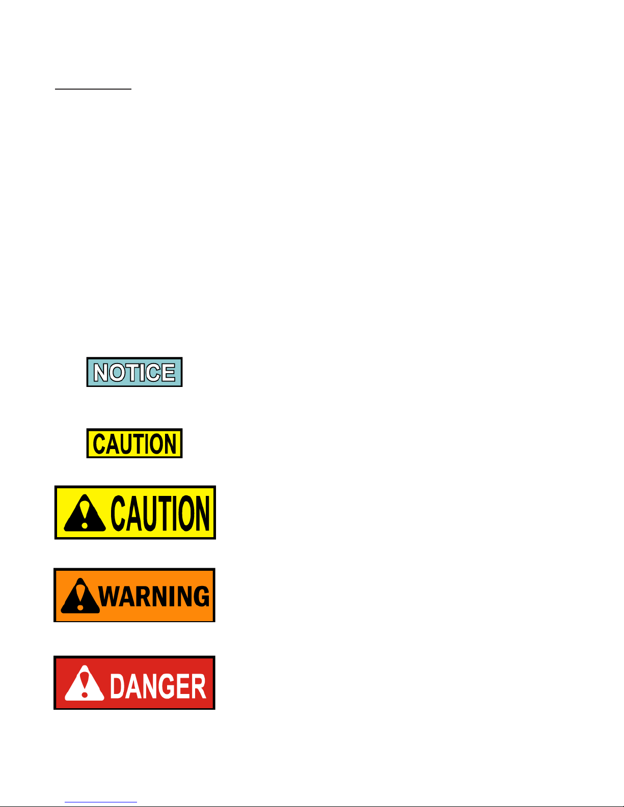
SAFETY ALERT SYMBOLS are used with DANGER, WARNING,
or CAUTION which indicates a personal injury OR type hazard.
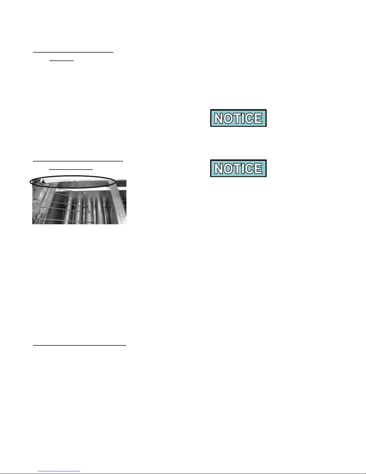
NOTICE is used to highlight especially important
information.
CAUTION used without the safety alert symbol indicates a
potentially hazardous situation which, if not avoided, may
result in property damage.
CAUTION used with the safety alert symbol indicates a
potentially hazardous situation which, if not avoided, may
result in minor or moderate injury.
WARNING indicates a potentially hazardous situation
which, if not avoided, could result in death or serious
injury.
DANGER INDICATES AN IMMINENTLY
HAZARDOUS SITUATION WHICH, IF NOT AVOIDED,
WILL RESULT IN DEATH OR SERIOUS INJURY.
April 2012
1-2
Model LVE-202, 203, 204
1-4. SAFETY (Continued)
OR
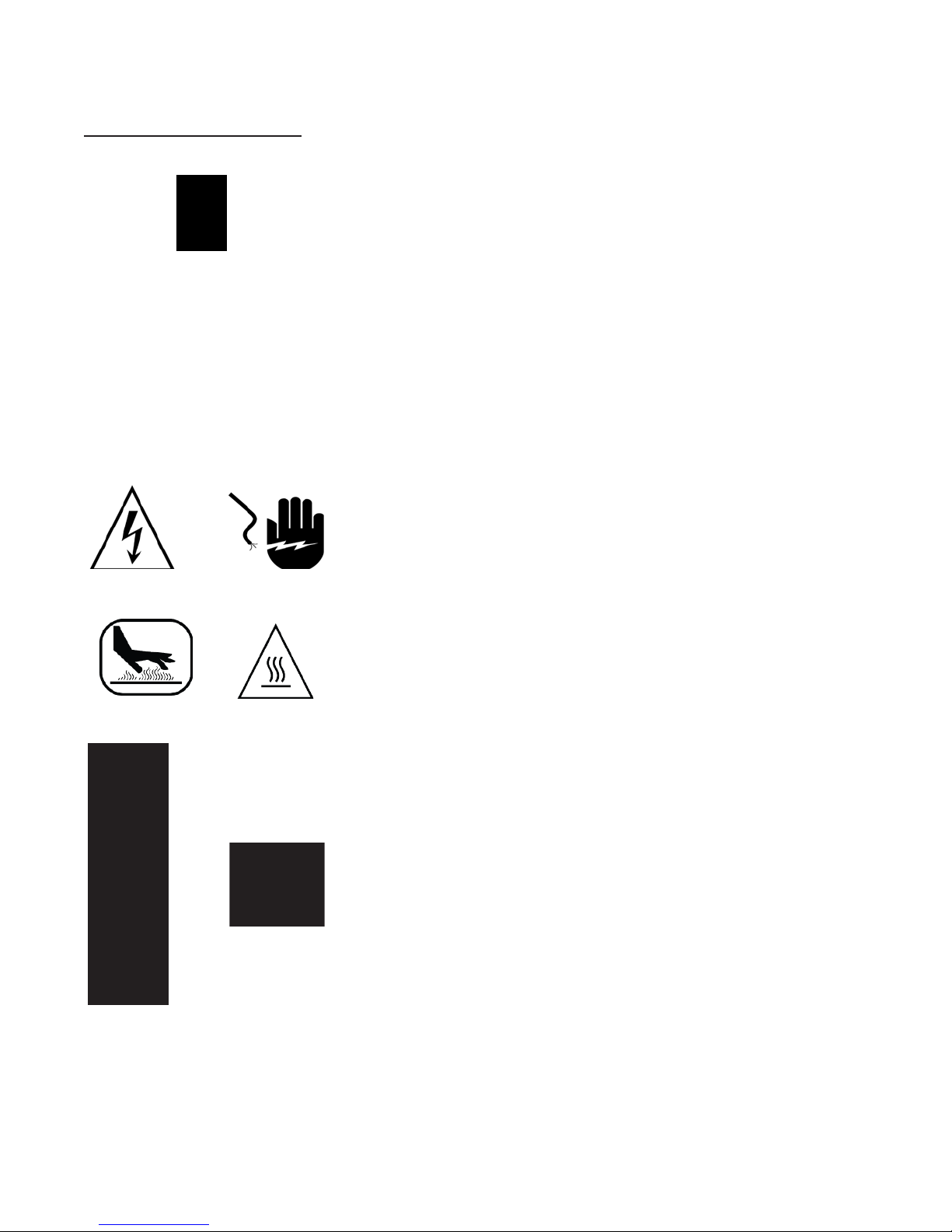
Equipotential Ground Symbol
Waste Electrical and Electronic Equipment (WEEE) Symbol
Shock Hazard Symbols
OR
Hot Surface Symbols
To Check or Conrm
Noise generated from this equipment is less than 70 dB(A)
Aug. 2012
1-3
Model LVE-202, 203, 204
SECTION 2. INSTALLATION
2-1. INTRODUCTION
2-2. UNPACKING
INSTRUCTIONS
This section provides the installation and unpacking instructions
for the Henny Penny LVE fryer.
Installation of this unit should be performed only by a
qualied service technician.
Do not puncture the fryer with any objects such as drills
or screws as component damage or electrical shock could
result.
Any shipping damage should be noted in the presence of the
delivery agent and signed prior to his or her departure.
1. Cut and remove the metal bands from the carton.
2. Remove the carton lid and lift the main carton off the fryer.
Figure 1
3. Remove corner packing supports (4).
4. Cut the stretch lm from around the carrier/rack box and
remove it from the top of the fryer lid.
5. Cut and remove the metal bands holding the fryer to the pallet.
• Do not r emove shipping brace from right side of fryer until
unit is in nal location as damage to fryer could result.
• Remove lter drain pan and JIB shelf from fryer before
removing fryer from pallet or damage to the unit could
result. Figure 1.
6. Remove the fryer from the pallet.
Take care when moving the fryer to prevent personal
injury. The fryer weighs approximately 600 lbs. (272 kg)
to 800 lbs. (363 kg)
.
Aug. 2012
2-1
Model LVE-202, 203, 204
2-3. SELECTING THE
FRYER LOCATION
2-4. LEVELING THE FRYER
The proper location of the fryer is very important for operation,
speed, and convenience. The location of the open fryer should
allow clearances for servicing and proper operation. Choose a
location which will provide easy loading and unloading without
interfering with the nal assembly of food orders. Operators have
found that frying from raw to nish, and holding the product in
warmers provides fast continuous service. Keep in mind, the best
efciency will be obtained by a straight line operation, i.e. raw in
one side and nished out the other side. Order assembly can be
moved away with only a slight loss of efciency.
To avoid re and ruined supplies, the area under the fryer
should not be used to store supplies.
To prevent severe burns from splashing hot oil, position
and install fryer to prevent tipping or movement.
Restraining ties may be used for stabilization.
For proper operation, the open fryer should be level from side-
to-side and front to back. Using a level placed on the at areas
around the vat collar, on the middle well, and adjust the casters
until the unit is level.
Casters adjustable up to 1.562 in (40mm)...see below.
Feb. 2011
2-2
Model LVE-202, 203, 204
2-5. VENTILATION OF
FRYER
2-6. ADJUSTING HEIGHT
OF TOP CAP
The fryer should be located with provision for venting into
adequate exhaust hood or ventilation system. This is essential
to permit efcient removal of steam exhaust and frying odors.
Special precaution must be taken in designing an exhaust
canopy to avoid interference with the operation of the fryer. We
recommend you consult a local ventilation or heating company to
help in designing an adequate system.
Ventilation must conform to local, state, and national codes.
Consult your local re department or building authorities.
Adjustable top cap to be used on all series exhaust hoods with
the exception of the universal exhaust hood (UH SERIES).
For UH SERIES top cap is to be removed - see Section 2-7.
Figure 1
Figure 2
2-7. REMOVAL OF TOP CAP
On the rear shroud of the fryer is an adjustable panel that must t
up against the vent hood. Figure 1.
Using a 3/8” socket, wrench or nutdriver, loosen the 3 acorn nuts
securing the panel. Figure 2.
Move the panel to t against the vent hood and then tighten the 3
acorn nuts.
Some installations (UH SERIES) may require the adjustable rear
shroud to be removed.
Using a Phillip’s-head screwdriver, remove two screws (one at
each end) securing the rear shroud and pull shroud from unit.
Aug. 2010
2-3
Model LVE-202, 203, 204
2-8. ELECTRICAL
REQUIREMENTS
Check the data plate, mounted on the inside of the left door, to
determine the correct power supply.
This fryer must be adequately and safely grounded
(earthed) or electrical shock could result. Refer to
local electrical codes for correct grounding (earthing)
procedures or in absence of local codes, with The National
Electrical Code, ANSI/NFPA No. 70-(the current edition).
In Canada, all electrical connections are to be made in
accordance with CSA C22.1, Canadian Electrical Code
Part 1, and/or local codes.
To avoid electrical shock, this appliance must be equipped
with an external circuit breaker which will disconnect all
ungrounded (unearthed) conductors. The main power
switch on this appliance does not disconnect all line
conductors.
(FOR EQUIPMENT WITH CE MARK ONLY!)
To prevent electric shock hazard this appliance must be
bonded to other appliances or touchable metal surfaces
in close proximity to this appliance with an equipotential
bonding conductor. This appliance is equipped with an
equipotential lug for this purpose. The equipotential lug is
marked with the following symbol
.
Aug. 2010
2-4

Model LVE-202, 203, 204
2-8. ELECTRICAL
REQUIREMENTS
(Continued)
An all pole, separate disconnect switch, with proper capacity
fuses or breakers must be installed at a convenient location
between the fryer and the power source, and must be installed
according to national and local codes. It should be an insulated
o
copper conductor rated for 600 volts and 90
C. For runs longer
than 50 feet (15.24 m), use the next larger wire size. CE units
require a minimum wire size of 6 mm to be wired to the terminal
block.
It is recommended that a 30 mA rated protective device such as
a residual current circuit breaker (RCCB), or ground fault circuit
interrupter (GFCI), be used on the fryer circuit.
Permanently connected electric fryers with casters must be
installed with exible conduit and a cable restraint, when
installed in the United States. See illustration at left. Holes are
available in the rear fryer frame for securing the cable restraint
to the fryer. The cable restraint does not prevent the fryer from
tipping.
The fryer is supplied with 2 different, 7 ft. (2.13 m) power
cord assemblies. The cord assembly with the NEMA L21-
20P twistlock plug is wired specically for McDonald’s Hood
Interlock Receptacle only, and supplies power to the controls.
DRYWALL CONSTRUCTION
Secure I-bolt to a building
stud. Do not attach to drywall
only. Preferred installation is
approximately six inches to either
side of service. Cable restraint
must be at least six inches
shorter than exible conduit.
The other power cord, supplying power to the heating system,
uses NEMA 15-60P Straight Plug, and each vat has its own power
cord assembly.
The supply power cords shall be oil-resistant, sheathed exible
cable, no lighter than ordinary polychloroprene or other
equivalent synthetic elastomer-sheathed cord.
Aug. 2010
2-5

Model LVE-202, 203, 204
2-9. DIMENSIONS
Aug. 2010
Casters adjustable up to 1.562 in (40mm)
2-6

Model LVE-202, 203, 204
2-10. LONWORKS FUNCTION
CONFIRMATION
Once the installation of the Henny Penny fryer is complete,
perform this procedure to verify that the LonWorks control in the
LVE is communicating with the computer console in the store.
1. Access the LonWorks system on the store’s computer console.
2. Turn the Main Power switch to the ON position on the Henny
Penny LVE fryer.
3. On one of the fryer controls, press both buttons
and “1. E-LOG” shows in the display.
4.
Press button until “9. COMM” & “LONWORKS ü”
show in the displays. (If “LONWORKS ---” shows in
display, the LonWorks control is not being acknowledged by
the main controls.)
5. Press button twice and “SRVC” & “PIN” show in the
displays. Press button under “SRVC”.
6. From the store’s console, click the WINK DEVICE button
and the displays on ALL LVE controls should ash, verifying
that the system is working properly.
If the the fryer and the store’s computer console is not
communicating, please contact the Technical Support Department
at 1-800-417-8405, 1-937-456-8405, or
technicalservice@hennypenny.com.
Oct. 2012
2-7
Model LVE-202, 203, 204
SECTION 3. OPERATION
3-1. OPERATING COMPONENTS Refer to explanations on the next pages.
1 2
4 5 73
6
8 9 1311 12
Aug. 2010
10 15
14
Figure 3-1
16
17
18
Figure 3-2
3-1

Model LVE-202, 203, 204
3-1. OPERATING
COMPONENTS
(Continued)
Refer to Figures 3-1 & 3-2 in conjunction with the description of
the functions below.
Fig.
No.
3-1 1
3-1 2
3-1 3
3-1 4
3-1 5
Item
No.
Description Function
This LED lights when the control calls for heat for the left vat(s), and
the elements come on and heat the oil
During normal operation, press this button to start and stop cook
cycles for the left basket; press to change displayed product; also used
ü
for
During normal operation, press this button to start and stop cook
cycles for the left basket; press to change displayed product; also used
for X to indicate NO or cancel
Digital Display Digital Display Shows the product codes; shows the timer countdown
during cook cycles; shows the prompts during the lter modes; shows
the selections in the Program Mode; shows the temperature of the
oil by pressing
languages)
During normal operation, press this button to start and stop cook
cycles for the right basket; press to change displayed product; press to
conrm prompts in the lter modes; also used for
or conrmation
to indicate YES or to conrm
; shows error codes (also displays in several
ü
to indicate YES
3-1 6
3-1 7
3-1 8
3-1 9
3-1 10
During normal operation, press this button to start and stop cook
cycles for the right basket; press to change displayed product; press
to deny prompts in the lter modes; also used for X to indicate NO or
cancel
This LED lights when the control calls for heat for the right vat(s), and
the elements come on and heat the oil
Press to turn on and off the heat system for the left vat(s)
Each product button LED lights when that particular product has been
selected
Press to select the desired product; press, during naming a product, to
place the letters under the button, in the name
Aug. 2010
3-2
Model LVE-202, 203, 204
3-1. OPERATING
COMPONENTS
(Continued)
Fig. No. Item No. Description Function
3-1 11 & 14
3-1 12
3-1 13
3-1 15
Used in the Programming and Filtering Modes;
also used for or buttons ; press to view the
following ltering stats:
a. the number of cook cycles before next lter
b. time and date of last lter cycle
c. the number of hours the existing lter has been used
Used in the Programming Modes; used in the Filtering
Modes; used in lling and emptying the vats; also used
for
button; press to view the following temperature
stats:
a. actual oil temperature in each vat
b. setpoint temperature for each vat
Used in the Programming Modes; also used for
button; press to display the following fryer information
and stats:
a. recovery information for each vat
b. selected primary and secondary display languaages
Press to turn on and off the heat system for the right
vat(s)
3-2 16
3-2 17
3-2 18
Aug. 2010
When turned to the ON position, power is supplied to
the controls and lter pumps
When lit blue , indicates an Automatic
Intermittent Filtration should be done at this time
When lit amber, indicates the JIB needs lled or
replaced
3-3

Model LVE-202, 203, 204
Figure 3-3
Fig.
No.
Item
No.
Description Function
3-3 1 Filter Drain Pan
Assy.
3-3 2 Basket Rest The baskets hang on this when not in use, or to drain the product
3-3 3 RTI Switch Only on fryers that have the RTI System at the location
3-3 4 Vat Covers Covers the vat when not in use
3-3 5a JIB Jug-in-a-Box for locations without RTI systems; holds oil
3-3 5b JIB Jug for locations with RTI systems; holds oil
Aug. 2010
Oil is drained into this pan and then is pumped through lters to
help prolong the use of the oil
after a cook cycle
3-4
 Loading...