

Page 1

INSTALLATION MANUAL
FlexFuison® PLATINUM ELECTRIC COMBI
FPE-615
FPE-621
FPE-115
FPE-121
FPE-215
FPE-221
Page 2

Directory of Contents
2
1
Introduction
4
1.1
About this manual
4
1.1.1
Explanation of signs
4
1.2
Use of the unit
6
1.3
Warranty
6
2
Safety information
7
3
Description of the unit
9
3.1
Overview of the unit
9
3.2
Planning drawing
11
3.3
Equipment and connection data
12
4
Transporting the unit
14
4.1
Information about transporting
14
4.2
Transporting to the installation site
14
4.2.1
Transporting on a pallet
15
4.2.2
Transporting without a pallet
15
4.2.3
Transporting by lifting and lowering
17
4.3
Unpacking the unit
17
5
Setting up the unit
18
5.1
Lifting the unit off the pallet
18
5.2
Setting up the unit on the equipment legs
19
5.3
Setting up the unit on a work surface
19
5.4
Aligning the unit
20
5.4.1
Aligning countertop units
21
5.4.2
Aligning floor-standing units
21
Directory of Contents
Page 3

Directory of Contents
3
5.5
Minimum clearances
22
6
Connecting the unit
24
6.1
Opening and closing the housing
24
6.1.1
Removing and attaching the side panel
24
6.2
Making the electrical connection
26
6.2.1
Connected loads for various connection voltages
26
6.2.2
Connecting to the electric mains
27
6.2.3
Connecting the electric power cable to the unit
28
6.3
Connecting the power optimizing system
30
6.4
Connecting the unit to the network
30
6.5
Basic settings
32
6.6
Making the water connection
34
6.6.1
Information about the water connection
34
6.6.2
Connecting hard and soft water
34
6.6.3
Connecting soft water twice
36
6.7
Making the wastewater connection
37
6.7.1
Information about the wastewater connection
37
6.7.2
Connecting the wastewater line permanently
37
6.8
Making the exhaust air connection
38
6.8.1
Information about the exhaust air connection
38
7
Putting the unit into service
39
7.1
Filling out the commissioning report
39
Page 4
1
Introduction
About this manual
4
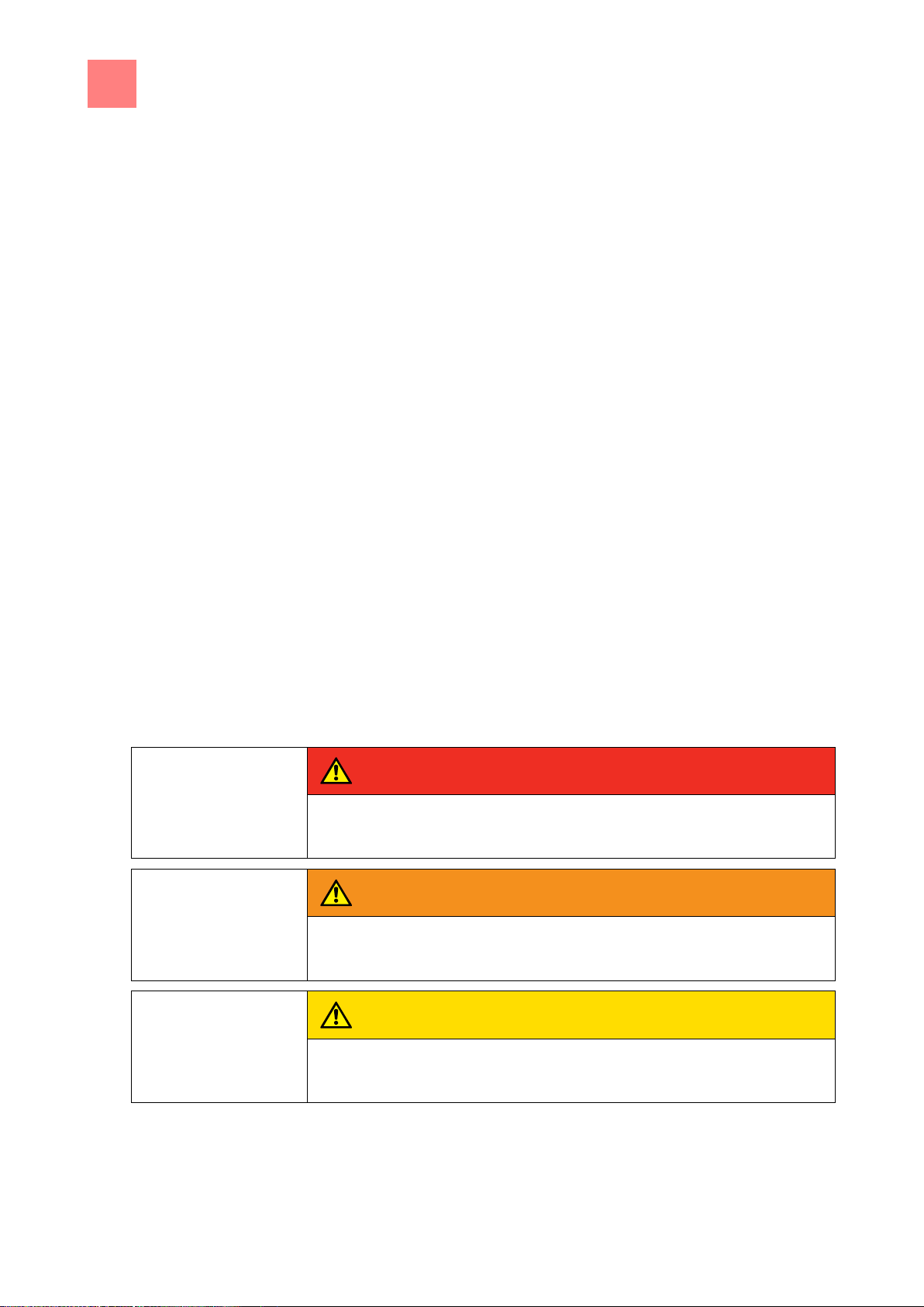
DANGER
Imminent threat of danger
Failure to comply will lead to death or very severe injuries.
WARNING
Possible threat of danger
Failure to comply can lead to death or very severe injuries.
CAUTION
Dangerous situation
Failure to comply can cause minor or moderate injuries.
1
1.1
Target group
Figures
1.1.1
Introduction
About this manual
The target group for the installation manual is trained technical personnel
that is familiar with installing and operating the unit.
All figures in this manual are intended as examples. Discrepancies between
these and the actual unit can arise.
The instruction manual is part of the unit and contains information on safe
installation of the unit.
Observe and adhere to the following instructions:
▪ Read the instruction manual in its entirety prior to installation.
▪ Make the instruction manual available to the installer at the operating site
at all times.
▪ Preserve the installation manual throughout the service life of the unit.
▪ Insert any supplements from the manufacturer.
▪ Pass on the installation manual to any subsequent operator of the unit.
Explanation of signs
Page 5

Introduction
1
About this manual
5
SAFETY INSTRUCTIONS
Material damage
Failure to comply can cause material damage.
NOTICE
Information
Notes for better understanding and operation of the unit.
Symbol / sign
Meaning
▪
Listing of information.
Action steps, which can be
performed in any sequence.
1.
2.
Action steps, which must be
performed in the prescribed
sequence.
Result of a listed action.
Page 6

1
Introduction
Use of the unit
6
1.2
1.3
Use of the unit
This unit is intended to be used solely for commercial purposes, particularly
in commercial kitchens.
This unit is certified in the following:
Warranty
The warranty is void and safety is no longer assured in the event of:
▪ Modifications or technical changes to the unit,
▪ Improper use,
▪ Incorrect startup, operation or maintenance of the unit,
▪ Problems resulting from failure to observe these instructions.
Page 7

Safety information
2
7
2
Ensuring conformity with
standards
Improper installation
Fire prevention
Organisational measures
Transportation and storage
Safety information
Observe applicable international, European and national laws, regulations,
standards and directives for the unit when transporting, setting up and
connecting it.
Risk of property damage and personal injury from improper
installation
▪ Install the unit only as specified in these installation instructions.
▪ Use only original spare parts.
Risk of fire from combustible surfaces
▪ Observe general fire prevention regulations.
Risk of property damage and personal injury from lack of
organizational measures
▪ Identify hazard areas when transporting, setting up and connecting the
unit.
▪ Prior to starting the installation work, notify any operators present about
the procedure.
▪ Prior to starting the installation work, discuss how to behave in an
emergency.
▪ Use equipment and protective gear suitable for the activity.
▪ Brace housing components to prevent them from falling over and
dropping.
Risk of personal injury and property damage from improper
transportation and improper storage.
▪ Store the unit in a dry, frost-free environment.
▪ Observe the safety regulations for the lifting gear used.
▪ Attach the unit to the lifting gear securely during transport and setup, and
prevent it from dropping.
▪ Transport the unit in an upright position, do not tilt or stack.
▪ Pay attention to protruding parts when transporting the unit without
packaging.
Page 8

2
Safety information
8
Setup
Electrical connection
Commissioning
Risk of property damage and personal injury from improper
setup
▪ Ensure that the installation area has adequate load-bearing capacity.
▪ Where safety shoes and protective gloves.
Risk of fire from improper connection
▪ Observe applicable regional regulations of the electrical utility.
▪ Ensure that only licensed electricians connect the unit.
▪ Ensure that the electrical system is earthed by a protective earthing
conductor.
▪ Note the information on the nameplate.
Risk of electric shock from live components.
▪ Prior to working on the electrical system, switch off the unit, disconnect
the electrical system from the mains and prevent power from being
switched on again. Check to ensure absence of voltage.
Risk of property damage and personal injury from improper
commissioning
▪ Read the operating instructions prior to commissioning. Observe the
safety instructions in this installation manual and in the "Safety
information" chapter of the operating instructions.
▪ Put the unit into service only after a successful function test following
assembly.
▪ Put the unit into service only after it has reached room temperature.
Page 9
Description of the unit
3
Overview of the unit
9
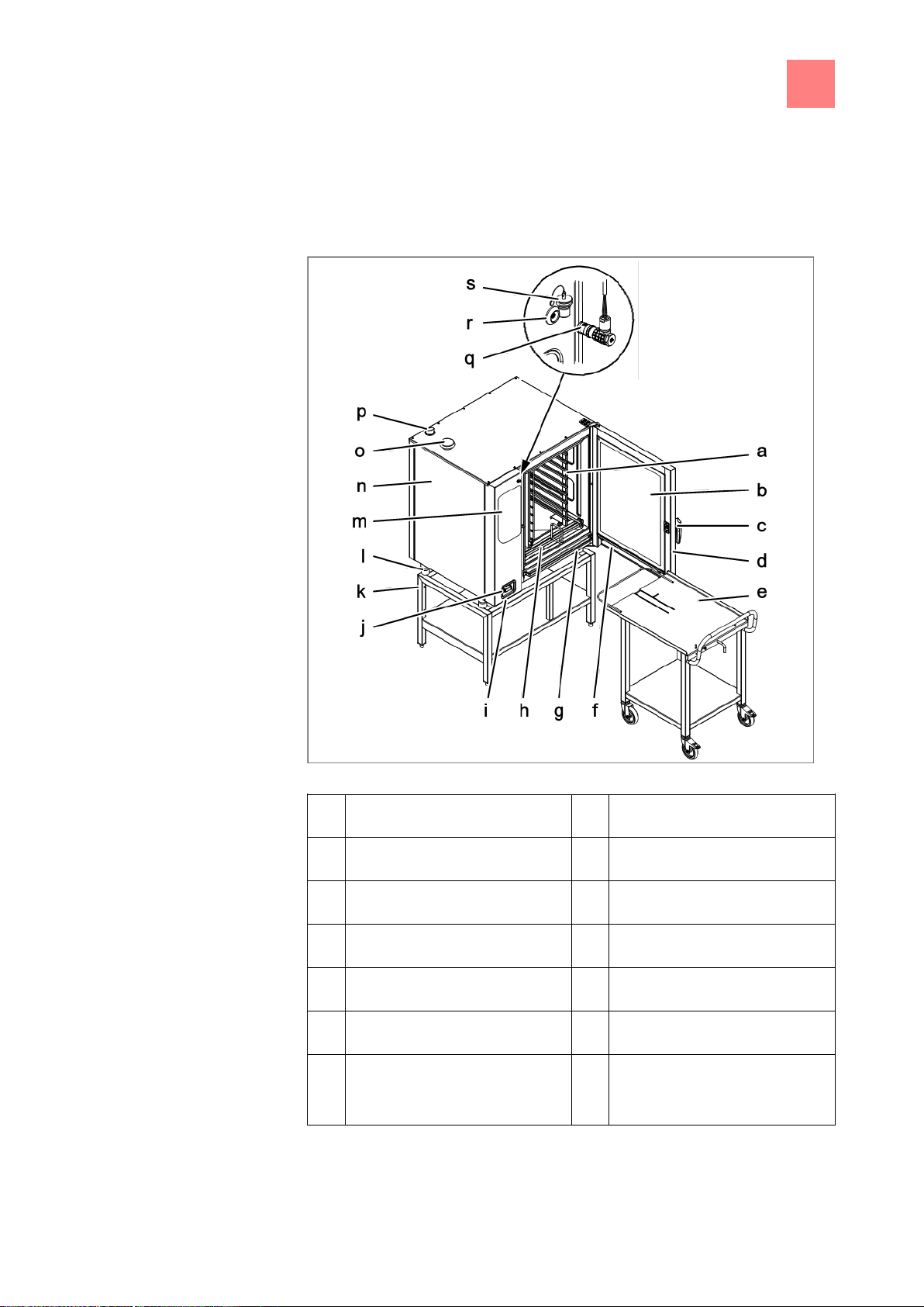
a
Tray rack
k
Base frame (optional)
b
Insulated window
l
Equipment foot
c
Door handle
m
Operating control
d
Cooking zone door
n
Housing
e
Tray rack trolley (optional)
o
Air intake connection fitting
f
Steam drain channel, door
p
Steam outlet connection fitting
g
Steam drain channel, unit
q
Core temperature sensor
(optional)
3
3.1
Description of the unit
Overview of the unit
FlexFusion with tray rack trolley
Page 10
3
Description of the unit
Overview of the unit
10
h
Guide rail for tray rack
(optional)
r
Connection (optional)
i
USB port (covered)
s
Protective cap (optional)
j
Hand shower (optional)
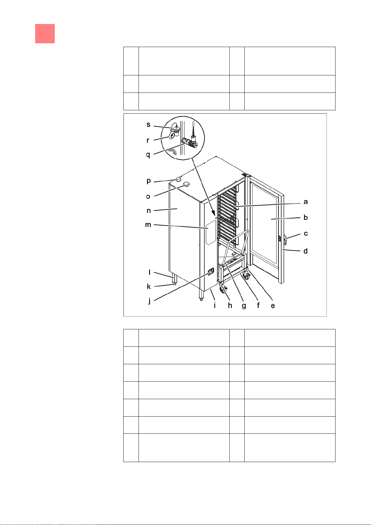
a
Tray rack
k
Equipment leg
b
Insulated window
l
Equipment foot
c
Door handle
m
Operating control
d
Cooking zone door
n
Housing
e
Guide rail (right)
o
Air intake connection fitting
f
Tray trolley
p
Steam outlet connection fitting
g
Push handle
q
Core temperature sensor
(optional)
FlexFusion with tray trolley
Page 11
Description of the unit
3
Planning drawing
11
h
Guide rail (left)
r
Connection (optional)
i
USB port (covered)
s
Protective cap (optional)
j
Hand shower
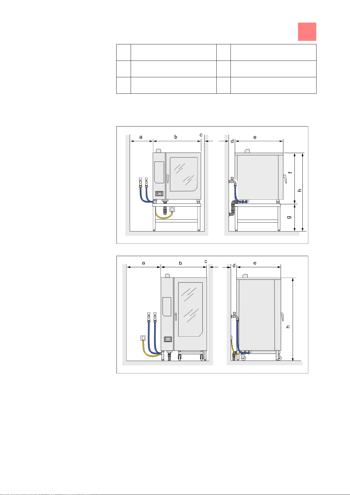
3.2
Planning drawing
Combisteamer – sizes 6 and 10
Combisteamer – size 20
Page 12

3
Description of the unit
Equipment and connection data
12
Size
a mm (in)
b mm (in)
c mm (in)
d mm (in)
e mm (in)
f mm (in)
g mm (in)
h mm (in)
6.15, 6.21
500 (20)
997 (39)
50 (2)
50 (2)
799 (31)
790 (31)
850 (33)
1640 (65)
10.15, 10.21
500 (20)
997 (39)
50 (2)
50 (2)
799 (31)
1060 (42)
580 (23)
1640 (65)
20.15, 20.21
500 (20)
1075 (42)
50 (2)
50 (2)
813 (32)
--
--
1960 (65)
Unit size
6.15
6.21
10.15
10.21
20.15
20.21
Dimensions
Unit
Length x width x height
mm
(in)
1000 x 800
x 790
(39 x 31 x
31)
1000 x 800
x 790
(39 x 31 x
31)
1000 x 800 x
1060
(39 x 31 x
42)
1000 x 800 x
1060
(39 x 31 x
42)
1075 x 813 x
1722
(42 x 32 x
68)
1075 x 813
x 1722
(42 x 32 x
68)
Packaged unit
Length x width x height
mm
(in)
1080 x 960
x 1020
(39 x 38 x
40)
1080 x 960
x 1020
(39 x 38 x
40)
1080 x 960 x
1280
(39 x 38 x
50)
1080 x 960 x
1280
(39 x 38 x
50)
1160 x 960 x
2200
(46 x 38 x
87)
1160 x 960
x 2200
(46 x 38 x
87)
Weight
Unit kg (lbs)
120 (265)
125 (276)
140 (309)
145 (320)
305 (672)
313 (690)
Packaged unit kg (lbs)
140 (309)
145 (320)
165 (364)
170 (375)
340 (750)
348 (767)
Emissions
Latent heat rejection (W)
1780
3670
2750
5400
5510
10200
Sensible heat rejection (W)
1190
2450
1840
3600
3670
7100
Noise level (db (A))
< 70
Ambient climate
5–40 °C (41-104°F), 95 % relative humidity, non-condensing
Electrical connection
Protection class
IPX5
3.3
Equipment and connection data
Page 13

Description of the unit
3
Equipment and connection data
13
Connected load (kW)
10.4
20.9
15.9
30.5
31.7
60.9
Type of connection
3 N PE 400 V AC 50 Hz
Maximum line current (A)
15.6
31.0
23.6
45.0
47.0
90.0
Recommended fusing (A)
3 x 16
3 x 35
3 x 25
3 x 50
3 x 63
3 x 100
Soft water connection
Type of water
Softened tap water, cold
Carbonate hardness CaCO3
(mmol/l)
< 1.5
Chloride Cl (mg/l)
< 50
Iron Fe (mg/l)
< 0.1
Connection pressure (hPa),
(bar)
200–600, 2–6
Type of connection
R ¾", male thread
Hard water connection
Type of water
Tap water, cold
Carbonate hardness CaCO3
(mmol/l)
Maximum 4
Connection pressure (hPa),
(bar)
200–600, 2–6
Type of connection
R ¾", male thread
Wastewater connection
Type of wastewater
Dirty water, maximum 80 °C (176°F)
Connection to unit
Connection fitting, 50 mm (2in) diameter
Page 14

4
Transporting the unit
Information about transporting
14
WARNING
Risk of property damage and personnel injury from tipping equipment
a) Do not linger next to or behind raised equipment.
b) Move raised equipment carefully.
SAFETY INSTRUCTIONS
Risk of physical damage from improper transport
a) Transport the unit upright.
b) Do not tilt or stack the unit.
c) Pay attention to protruding parts when transporting the unpacked unit.
4
4.1
4.2
Transporting the unit
Information about transporting
Crossing a grate with the tray trolley
➢ Prior to transporting the unit to the installation site, ensure that:
a) The route has adequate load-bearing capacity; place rails or metal plates
underneath if necessary.
b) Wall openings are large enough. Removing the packaging reduces the
clear width required Equipment and connection data [➙ 12] .“
Transporting to the installation site
Page 15

Transporting the unit
4
Transporting to the installation site
15
SAFETY INSTRUCTIONS
Risk of physical damage from improper lifting of the unit
a) Lift size 6 and size 10 units only with the aid of wooden beams placed
underneath.
4.2.1
4.2.2
Requirement
Transporting on a pallet
a) Move the pallet truck under the pallet.
b) Raise the unit on the pallet.
Transporting the unit on a pallet
c) Move the unit to the installation site.
Transporting without a pallet
Unit sizes 6 and 10
➢ Packaging removed except for the pallet
a) Move the pallet truck under the unit from the right.
b) Place the wooden beams on the lift forks and slide under the unit.
c) Lift the unit off the pallet.
Page 16

4
Transporting the unit
Transporting to the installation site
16
Requirement
Transporting unit sizes 6 and 10 without a pallet
d) Move the unit to the installation site.
Unit size 20
➢ Packaging removed except for the pallet
a) Move the pallet truck under the guide rails of the unit from the right.
b) Lift the unit off the pallet.
Transporting unit size 20 without a pallet
c) Move the unit to the installation site.
Page 17

Transporting the unit
4
Unpacking the unit
17
DANGER
Risk of fatal injury from falling load
a) Do not linger under a suspended load.
b) Cordon off the hazard area according to regulations.
SAFETY INSTRUCTIONS
Risk of physical damage from tightened lifting straps
a) Always lift the unit with lifting straps and a spreader bar.
WARNING
Risk of injury from sharp edges
Wear protective gloves.
NOTICE
When unpacking the unit, inspect it for transport damage. Do not install
damaged units or put into service. Enter the information from the
nameplate into the commissioning report.
4.2.3
4.3
Transporting by lifting and lowering
a) Guide the lifting straps under the pallet and attach them to the spreader
bar.
b) Brace the unit to prevent tipping.
c) Carefully lift the unit onto the pallet.
Unpacking the unit
a) Remove the packaging.
b) Pull the protective film off the unit.
c) Remove the packaging material from the cooking zone completely.
d) Lift the unit off the pallet and place in position.
e) Clean the unit
see the "Cleaning and maintaining the unit" chapter in the
operating instructions.
f) Separate and dispose of the packaging material.
Page 18

5
Setting up the unit
Lifting the unit off the pallet
18
WARNING
Risk of burns from spraying hot fat
a) Set up deep fat fryers outside the range of the hand shower.
CAUTION
Risk of crushing from improper setup
a) Protect the unit and work area during setup and alignment.
WARNING
Risk of fire from failure to observe applicable regional fire prevention
regulations
a) Observe applicable regional fire prevention regulations.
SAFETY INSTRUCTIONS
Risk of physical damage from overheating of the unit
a) Do not set up the unit close to heat sources.
CAUTION
Risk of property damage and personnel injury from tipping equipment
a) Do not linger next to or behind raised equipment.
b) Move raised equipment carefully.
SAFETY INSTRUCTIONS
Risk of physical damage from lifting the unit incorrectly
a) Place the forks of the lift truck next to the waste trap.
5
5.1
Requirement
Setting up the unit
Lifting the unit off the pallet
➢ Unit unpacked
➢ Protective film removed
➢ Unit cleaned
Page 19

Setting up the unit
5
Setting up the unit on the equipment legs
19
5.2
Requirement
5.3
Requirement
Lifting the unit off the pallet
a) Slide the forks of the pallet truck under the unit and to the right of the
waste trap.
b) Lift the unit off the pallet.
Setting up the unit on the equipment legs
➢ The floor must carry the weight of the unit
a) Lift the unit with the pallet truck.
b) Move the unit to the installation site.
c) Place the unit on the floor.
d) Set up the unit in accordance with the planning drawing Planning
drawing .
Setting up the unit on a work surface
➢ The base frame must carry the weight of the unit
➢ Base frame levelled
➢ Base frame set up in accordance with the planning drawing Planning
drawing
a) Lift the unit.
Page 20

5
Setting up the unit
Aligning the unit
20
a
Lift fork
d
Stud bolt
b
Waste trap on the unit
e
Equipment leg
c
Base frame
f
Unit
WARNING
Risk of burns from missing stickers
a) Attach stickers if the upper insertion rails are higher than 1.60 m (63in).
5.4
Setting up the unit on a work surface
b) Place the unit over the stud bolts on the work surface.
Attach warning sign regarding insertion height
a) Clean the adhesion surface for the sticker.
b) Attach the sticker to the cooking zone door at a height of 1.6 m (63in).
Aligning the unit
Page 21

Setting up the unit
5
Aligning the unit
21
NOTICE
The tray trolley is needed to align a floor-standing unit.
Prepare the tray trolley.
5.4.1
Requirement
5.4.2
➢ Base frame levelled
a) Place a spirit level on the unit.
b) Screw the equipment legs in or out to level the unit.
Aligning floor-standing units
a) Screw the equipment legs in or out to align the unit.
b) Open the cooking zone door.
Aligning countertop units
Aligning the unit with the tray trolley
Page 22

5
Setting up the unit
Minimum clearances
22
a
Tray trolley
d
Equipment leg
b
Distance between roller and
support rail
e
Roller
c
Support rail
a
Ceiling
b
Baking oven
c
Deep fat fryer
5.5
c) Place the tray trolley against the support rails.
d) Screw the equipment legs in or out until the rollers are 1 to 5 mm above
the support rails.
e) Retract the tray trolley.
f) Level the support rails.
g) Push the tray trolley against the unit until it stops.
h) Remove the push handle.
i) Close the cooking zone door.
⇨ The unit is aligned correctly.
Minimum clearances
FlexFusion minimum clearances
The following clearances from walls, ceilings or other equipment must be
provided when setting up the unit:
▪ Left, right and behind: at least 50 mm (2in).
▪ If possible at the left, 500 mm (20in) for service work
Page 23

Setting up the unit
5
Minimum clearances
23
▪ If possible at the left, 800 mm (31in) for parking the trolley tray
▪ At the left, 500 mm (20in) to heat sources (baking ovens) so that the
cooling air for the unit is not heated.
▪ Left and right, one length of the hand shower so that no water can be
sprayed into the hot deep fat fryer.
▪ To ceilings, at least 500 mm (20in). There must be no water, gas or
electric lines in the ceiling above the unit.
Page 24

6
Connecting the unit
Opening and closing the housing
24
DANGER
Risk of electric shock
a) Prior to working on the unit, ensure that the unit has been disconnected
from the mains.
b) Do not operate the unit with the housing open.
WARNING
Risk of injury from sharp edges
a) Wear protective gloves.
SAFETY INSTRUCTIONS
Risk of physical damage from damage to the lines
a) Remove and attach housing components carefully.
6
6.1
6.1.1
Connecting the unit
Opening and closing the housing
Removing and attaching the side panel
Removing the side panel
a) Unscrew the bolts on the bottom of the side panel.
b) Pull the bottom of the side panel forward.
Removing and attaching the side panel
c) Remove the side panel.
Page 25

Connecting the unit
6
Opening and closing the housing
25
SAFETY INSTRUCTIONS
Risk of physical damage from squeezing the lines
When attaching the side panel, make sure that no lines are squeezed.
SAFETY INSTRUCTIONS
Risk of physical damage from a loose side panel
a) The side panel must be in contact with the unit on all sides.
Attaching the side panel
a) Insert the top edge of the side panel.
a) Carefully push the bottom of the side panel inward.
b) Secure the bottom of the side panel with bolts.
c) Check that the side panel is in contact with the unit on all sides.
Page 26

6
Connecting the unit
Making the electrical connection
26
Unit size
6.15
6.21
10.15
10.21
20.15
20.21
Electricity network type
3PE / AC 50/60Hz , 3NPE / AC 50/60Hz
Voltage (V)
200
Connected load (kW)
9.7
16.3
14.7
25.5
29.4
50.9
Fusing (A)
35
50
50
80
100
180
Voltage (V)
208
Connected load (kW)
10.2
17.4
15.7
27.3
31.4
54.6
Fusing (A)
35
50
50
80
100
180
Voltage (V)
230
Connected load (kW)
12.6
21.4
19.3
33.6
38.6
67
Fusing (A)
35
63
63
100
125
180
Voltage (V)
240
Connected load (kW)
13.7
23.3
21
36.5
42
72.9
Fusing (A)
35
63
63
100
125
180
Voltage (V)
380
Connected load (kW)
9.4
18.9
14.4
27.6
28.7
55
Fusing (A)
16
35
25
50
50
100
Voltage (V)
400
6.2
6.2.1
Making the electrical connection
▪ Ensure that only licensed electricians connect the unit.
▪ Note the information on the nameplate.
▪ Observe applicable regional regulations of the electrical utility.
Connected loads for various connection
voltages
Page 27

Connecting the unit
6
Making the electrical connection
27
Connected load (kW)
10.4
20.9
15.9
30.5
31.7
60.9
Fusing (A)
16
35
25
50
50
100
Voltage (V)
415
Connected load (kW)
11.2
22.5
17.1
32.8
34.1
65.5
Fusing (A)
16
35
25
50
50
100
Voltage (V)
440
Connected load (kW)
10.4
20.9
15.8
30.5
31.5
60.9
Fusing (A)
16
35
25
50
50
100
Voltage (V)
480
Connected load (kW)
12.3
20.9
18.9
32.6
37.6
65.1
Fusing (A)
16
35
25
50
50
100
6.2.2
Electric power cable
Residual-current protective
device
Connecting to the electric mains
An electric power cable of the type HO7RN-F must be used to connect the
unit to the electric mains.
The unit can be connected to a residual-current protective device. The
residual-current protective device must incorporate a residual-current
protective switch of type B (RCD Type B) in order to detect AC fault currents,
pulsating DC currents and continuous DC currents.
RCD switch type B circuit symbol
Page 28

6
Connecting the unit
Making the electrical connection
28
SAFETY INSTRUCTIONS
Risk of property damage and personal injury from improper installation
a) In the case of a permanent electrical connection, install an all-phase
disconnect switch before the unit.
SAFETY INSTRUCTIONS
Risk of property damage and personal injury from improper installation
a) The plug-in connection must be readily accessible.
A, B, C, D
Power optimizing
system
PE
Protective earth
13, 14
Floating contact
X1
Mains connection
L1, L2, L3
Phases
X2
Power optimizing system
connection
N
Neutral conductor
Permanent connection
Plug-in connection
6.2.3
Install an all-phase disconnect switch if the unit will be connected
permanently to the electric mains.
If the unit will be connected to the electric mains by a plug, use a plug and
socket that comply with IEC 60309. The socket must be readily accessible
so that the unit can be disconnected from the electric mains at any time.
Connecting the electric power cable to the unit
Electrical connection terminal diagram in the unit
Page 29

Connecting the unit
6
Making the electrical connection
29
Model
Length mm (in)
6.15, 6.21
1000 (39)
10.15, 10.21
1200 (47)
20.15, 20.21
720 (28)
a
Connection terminals
c
Electric power cable
b
Cable tie
d
Cable gland
Requirement
Length of connection cable in the unit
Connecting the electric power cable
➢ Electrical connection to the unit matches the information on the
nameplate
➢ Housing open
➢ Electric power cable sufficiently long
a) Insert the electric power cable into the unit through the cable gland.
b) Connect the electric power cable in accordance with the terminal
diagram.
c) Secure the electric power cable to the unit with cable ties.
d) Tighten the cable gland securely to provide strain relief.
Page 30

6
Connecting the unit
Connecting the power optimizing system
30
Type of network
Ethernet
Cabling
In accordance with EN 50173
Cable quality
4-twin, shrouded patch cable
Cat-6 S/FTP
Connection to the unit
Shrouded RJ45 plug
Cable length in the unit
As per electric power cable
6.3
Requirement
6.4
Connecting the power optimizing system
The unit can be connected to a power optimizing system. The line length in
the unit corresponds to the length of the electric power cable.
➢ Unit disconnected from the electric mains
➢ Left side panel removed
a) Pull the connection cable into the unit through the opening next to the
entry for the electric power cable.
b) Bring the connection cable to the connection terminals.
c) Attach the connection cable in accordance with the terminal diagram.
d) Secure the connection cable with cable ties.
e) Enter the power optimizing system in the basic settings.
Connecting the unit to the network
The units can be connected to an Ethernet network with a RJ45 plug.
Requirements for network connection
Page 31

Connecting the unit
6
Connecting the unit to the network
31
a
RJ45 socket
d
Cable tie
b
RJ45 plug
e
Feed-through in the base of the
unit
c
Network cable
f
Ferrite rings
Requirements
Connecting the network cable
➢ Unit is disconnected from the electric mains
➢ Side panel is removed
a) Pull the network cable alongside the electrical connection into the unit.
b) Lead the network cable through the two ferrite rings with one turn each.
c) Connect the network cable to the unit with the RJ45 plug.
d) Put the unit into service and under basic setting enter the network
address or select DHCP.
Page 32

6
Connecting the unit
Basic settings
32
a
Start menu for FlexFusion
ChefsTouch
d
Key for “Unit functions”
b
Key for
FlexFusion Help
e
Key for “Back”
c
Language selection
Basic setting
No.
Standard
value
Setting range
Explanation
Actual voltage
1
Enter the local, mean voltage
between the outer cables.
Date / Time
2 dd mm yyyy/
hh mm
6.5
Requirements
Basic settings
Start menu for FlexFusion ChefsTouch
By entering the password "2100", the basic settings for the installation can
be displayed and changed.
➢ The unit is switched on
a) Touch the key for “Unit functions” in the main menu.
b) Enter the password “2100” with the keypad.
c) Select and set parameters in the menu.
Page 33

Connecting the unit
6
Basic settings
33
Basic setting
No.
Standard
value
Setting range
Explanation
Altitude
3 0 0 - 3
Request the altitude above
sea level from the closest
weather station. If the altitude
is unknown, enter 0 – 500 m.
▪ 0 = 0 - 500 m (0 - .31 mi)
▪ 1 = 501 – 1000 m (.31 -
.62 mi)
▪ 2 = 1001 – 1500 m (.62 -
.93 mi)
▪ 3 = > 1500 m (.93 mi)
Audio setting
4
20
0 – 180 s
Duration of the audible signal
0 = Signal off
Units
5 Metric/Imperial
Water filter
maintenance
6 Litres > 0
0 = No maintenance
message
Water quantity up to the
maintenance message
Network
7 Network address and
DHCP
Select Ethernet interface
Kitchen control
technology
Disabled/enabled
Address of port and unit can
be entered.
80% power
4
0
0 = No
1 = Yes
Yes = Power limited to 80 %
(for special applications)
Power optimizing
system
connected?
5
0
0 = No
1 = Yes
If the power optimizing
system is connected, "Yes"
must be selected in order for
the unit to heat.
Page 34

6
Connecting the unit
Making the water connection
34
6.6
6.6.1
6.6.2
Making the water connection
Information about the water connection
Installation work involving drinking water must be performed by an
authorised plumbing contractor. Observe applicable regional regulations with
regard to drinking water installations and connection data.Equipment and
connection data [➙ 12]
Connecting hard and soft water
The unit is equipped with a connection for:
▪ Soft water for generating steam
▪ Hard water for cooling, rinsing and WaveClean
Page 35

Connecting the unit
6
Making the water connection
35
SAFETY INSTRUCTIONS
Hygiene risk from contaminated drinking water
a) The connection to the drinking water supply must be equipped with a
backflow preventer.
NOTICE
Always connect hard and soft water to the unit
SAFETY INSTRUCTIONS
Risk of physical damage from the wrong water quality
a) Ensure that the water quality complies with the equipment and
connection data.
SAFETY INSTRUCTIONS
Hygiene risk from contaminated drinking water
a) The connection to the drinking water supply must be equipped with a
backflow preventer.
a
Soft water tap
e
Hard water connection fitting
b
Backflow preventer, installed
f
Hard water hose
c
Hose
g
Backflow preventer, installed
d
Soft water connection fitting
h
Hard water tap
Requirement
➢ Water quality meets specifications
➢ Backflow preventers installed
➢ Required water pressure available
Hard and soft water connection
Page 36

6
Connecting the unit
Making the water connection
36
a
Soft water tap
e
Hard water connection fitting
b
Backflow preventer
f
Dirt filter
c
Hose
g
T-piece
d
Soft water connection fitting
h
Seal
6.6.3
Requirement
➢ Pressure-resistant hoses suitable for drinking water available
a) Connect the hoses to the water taps.
b) Open the water taps and flush the hoses.
c) Insert dirt filters into the two water connection fittings.
d) Connect hoses to the unit.
e) Open the water taps and check the threaded fittings for leaks.
Connecting soft water twice
If only a soft water connection is available at the installation site, the hard
water connection fitting and the soft water connection fitting must be
connected by means of a T-piece.
Soft water connection twice
➢ Hose connected to soft water tap
a) Insert a dirt filter into the hard and soft water connection fittings.
b) Connect the T-piece with seals to the connection fittings.
c) Connect hose with seal to the T-piece.
d) Open the soft water tap and check the threaded fittings for leaks.
Page 37

Connecting the unit
6
Making the wastewater connection
37
a
Wastewater discharge from
unit
d
Wastewater system trap
b
Wastewater line
e
Pipe clamp
c
Wastewater system
f
Vacuum breaker valve
NOTICE
If a waste trap is installed in the wastewater system, a vacuum breaker
must be installed in the wastewater line.
6.7
6.7.1
6.7.2
Requirement
Making the wastewater connection
Information about the wastewater connection
Installation work involving wastewater must be performed by an authorised
plumbing contractor. Observe the applicable regional regulations of the
sewage utility involved.
Connecting the wastewater line permanently
Connecting the wastewater line permanently
Polypropylene (PP) pipes and elbows
▪ Heat-resistant to 95 °C (203°F)
▪ Nominal diameter 50 mm (2in)
▪ Maximum pipe length 1.0 m (39in)
Page 38

6
Connecting the unit
Making the exhaust air connection
38
CAUTION
Risk of physical damage from fouling of the exhaust air ducts
a) Do not incorporate the exhaust air line directly into an exhaust air
system.
CAUTION
Risk of corrosion damage from condensate
a) Install the exhaust air line such that condensate cannot collect.
6.8
6.8.1
Requirement
a) Install wastewater line up to connection to the sewer system.
b) Secure the wastewater line with clamps.
c) Pour tap water into the wastewater trap on the unit.
Making the exhaust air connection
Information about the exhaust air connection
When setting up the unit under an exhaust hood, observe the applicable
regional regulations for ventilation systems.
Flexible aluminium hose
▪ Nominal diameter 63 mm for sizes 6 and 10
▪ Nominal diameter 76 mm for size 20
▪ Maximum length of hose 2.5 m (98in)
▪ Temperature-resistant to 180 °C (356°F)
a) Connect hose to exhaust air connection fitting.
b) Route hose to the exhaust hood with about a 3° rise.
c) Secure end of hose about 50-200 mm (2-8in) below the exhaust hood.
Page 39

Putting the unit into service
7
Filling out the commissioning report
39
General
Yes
No
Information from the nameplate entered?
SN: _____________________________ Typ: _____________________________
QN (Hi): _____________________________
E: ________________________________________________________________
Bez: ______________________________________________________________
Item-Nr.: _____________________________ (if listed)
Obvious damage to the unit?
What and where?:
______________________________________________________________________________
Unit levelled?
Elements that can tilt levelled? (for instance: pans)
Electrical connection
Yes
No
Power connection made properly?
Equipotential bonding
Power optimizing system
Floating contact
…
Electrical connections made properly?
Residual-current protective device connected immediately before this unit?
Residual-current protective device connected before this and other units?
7
7.1
Putting the unit into service
Filling out the commissioning report
Page 40

7
Putting the unit into service
Filling out the commissioning report
40
Water connection
Yes
No
Minimum connection pressure available?
Connection pressure: _______________ bar
Water connection made properly?
Lines and connections have no leaks?
Mixing battery mounted properly?
Wastewater connection
Yes
No
Wastewater connection made properly?
On-site waste trap
Vacuum breaker
Funnel discharge
Wastewater pipe dimension: ____________________ mm (in)
Exhaust air connection
Yes
No
Set up under exhaust hood?
Connected to exhaust air duct?
Exhaust air pipe dimension: ____________________ mm (in)
Exhaust air pipe length: ________________________ m (in)
Final notes
Yes
No
Was the unit put into service?
Comments:
Operator trained?
Electrical installation was provided by:
Company
Installer
City, date
Signature
Page 41

Putting the unit into service
7
Filling out the commissioning report
41
Water installation was provided by:
Company
Installer
City, date
Signature
Wastewater installation was provided by:
Company
Installer
City, date
Signature
Exhaust air connection was provided by:
Company
Installer
City, date
Signature
Operator training was provided by:
Company
Installer
City, date
Signature
Page 42

Henny Penny Corporation
P.O.Box 60
Eaton,OH 45320
1-937-456-8400
1-937-456-8402 Fax
Toll free in USA
1-800-417-8417
1-800-417-8434 Fax
www.hennypenny.com
Henny Penny Corp., Eaton, Ohio 45320, Revised 2-19-15
 Loading...