

Henny Penny FPDE615.615, FPDE615.216, FPDE115.615, FPDE115.621, FPDE121.615 Installation Manual
...
Model
FPDE615.615
Installation
Manual
FM 05-253 • 23/08/2018
Read the operating manual prior to commissioning
FPDE615.216
FPDE621.615
FPDE621.621
FPDE115.615
FPDE115.621
FPDE121.615
FPDE121.621
FlexFusion® ELECTRIC
PLATINUM COMBI TEAM
PLATINUM
FUSION
FLEX
FM05-253
en-US

%&&'(
)*)+,
-*%!
#$.
/"01
,/"01!
#$.
/"01"1"1
,/"01"1
222)&(&)
! 3

Directory of contents
3Installation instructions
1Introduction......................................................................... 5
1.1About this manual ............................................................................ 5
1.1.1Explanation of signs .................................................................................. 6
1.2Staff qualification ............................................................................. 7
1.3Use of the unit................................................................................... 7
1.4Warranty............................................................................................ 7
2Safety information.............................................................. 8
3Description of the unit ..................................................... 10
3.1Overview of the unit ....................................................................... 10
3.2Equipment and connection data................................................... 10
4Transporting the unit ....................................................... 15
4.1Transporting the unit to the installation site ............................... 15
4.2Unpacking the unit ......................................................................... 15
5Setting up the unit............................................................ 17
5.1Minimum clearances ...................................................................... 17
5.2Lifting the unit off the pallet .......................................................... 18
5.3Placing the unit on the equipment legs........................................ 19
5.4Aligning the unit ............................................................................. 19
6Connecting the unit.......................................................... 20
6.1Opening and closing the housing................................................. 20
6.1.1Removing and attaching side wall........................................................... 20
6.2Making the power connection....................................................... 21
6.2.1Matching the unit to the connection voltage ............................................ 23
6.2.2Connecting the power connection cable ................................................. 25
6.2.3Connecting the power optimisation system............................................. 26
6.2.4Connecting to the potential equalisation circuit ....................................... 27
6.3Connecting the kitchen management system ............................. 27
6.4Making the basic control setting................................................... 29
6.4.1Changing the basic control setting .......................................................... 29
6.5Making the water connection ........................................................ 30
6.5.1Connecting the tap water connection line ............................................... 30
6.5.2Connecting softened tap water to both connections ............................... 31
6.6Making the wastewater connection .............................................. 32
6.6.1Connecting the wastewater line to a permanent connection................... 32
6.7Making the exhaust air connection .............................................. 33
6.7.1Connecting the exhaust air line ............................................................... 34
7Checking operation.......................................................... 35
7.1Checking the controls.................................................................... 35
7.2Checking the monitoring of the cooking zone door ................... 35
FM05-253

Directory of contents
4 Installation instructions
7.3Heating the unit up and rinsing it out........................................... 36
8Putting the unit into service ............................................ 37
8.1Filling out the Commissioning report........................................... 37
FM05-253

Introduction
5Installation instructions
1 Introduction
1.1 About this manual
The instruction manual is part of the unit and contains information on
safe installation of the unit.
Observe and adhere to the following instructions:
• Read the instruction manual in its entirety prior to installation.
• Make the instruction manual available to the installer at the
operating site at all times.
• Preserve the installation manual throughout the service life of the
unit.
• Insert any supplements from the manufacturer.
• Pass on the installation manual to any subsequent operator of the
unit.
Target group The target group for the installation manual is trained technical
personnel that is familiar with installing and operating the unit.
Figures All figures in this manual are intended as examples. Discrepancies
between these and the actual unit can arise.
FM05-253
Introduction
6 Installation instructions
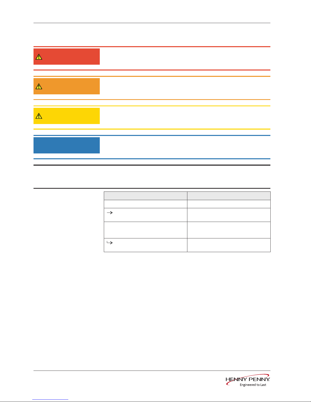
1.1.1 Explanation of signs
DANGER
Imminent threat of danger
Failure to comply will lead to death or very severe injuries.
WARNING
Possible threat of danger
Failure to comply can lead to death or very severe injuries.
CAUTION
Dangerous situation
Failure to comply can lead to slight or moderately severe injuries.
NOTICE
Property damage
Failure to comply can cause physical damage.
INFORMATION
Information
Notes for better understanding and operation of the unit.
Symbol / sign Meaning
• Listing of information.
Action steps, which can be performed in
any sequence.
1.
2.
Action steps, which must be performed
in the specified sequence.
Result of an action performed or
additional information about it.
FM05-253
Introduction
7Installation instructions
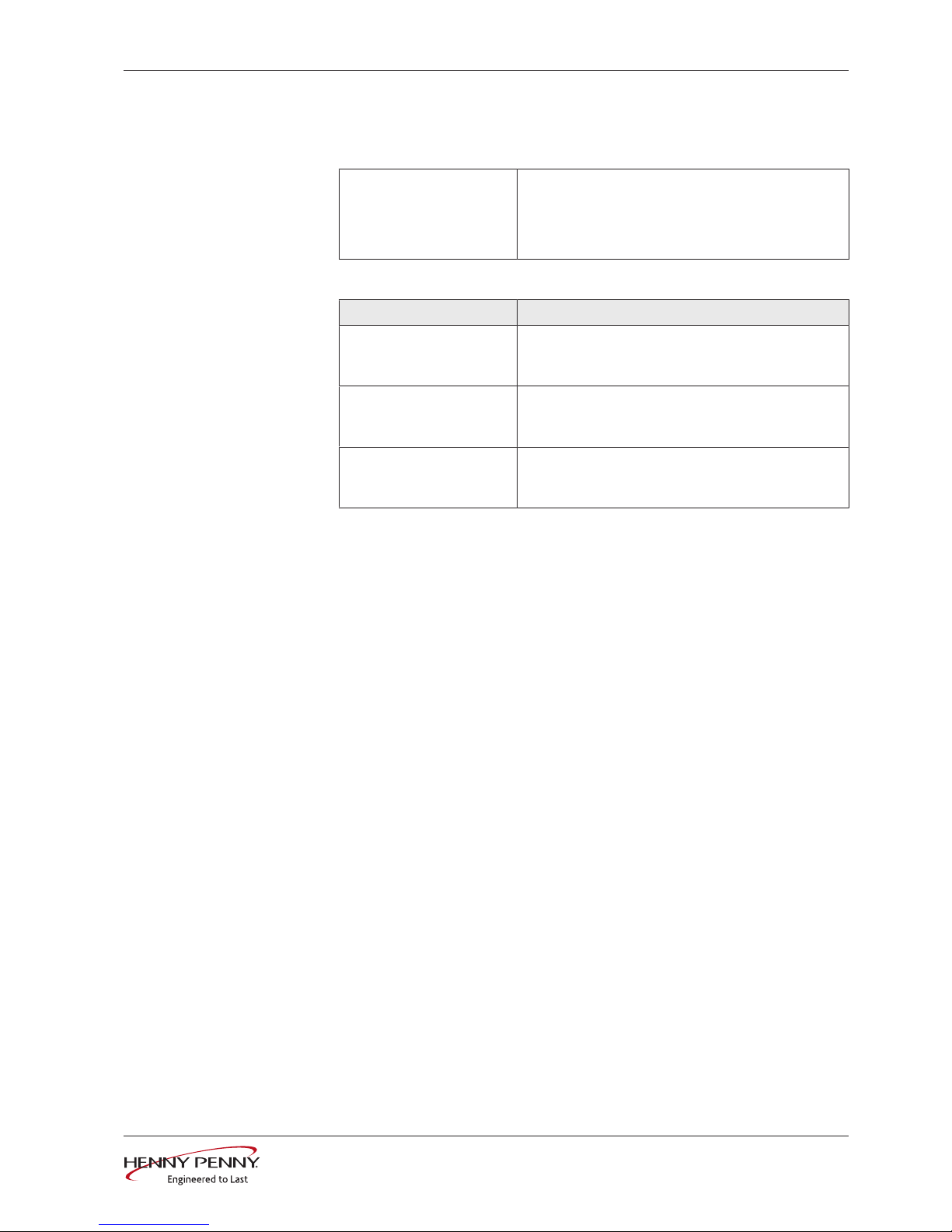
1.2 Staff qualification
Explanation of qualification
Skilled staff • Skilled staff are those, who due to their profes-
sional training, knowledge and experience as well
as their knowledge of the relevant standards can
assess the tasks given to them and recognize any
possible dangers.
Type of activity Qualification
Power connection • Electrician
• Specific professional training
• Employee of the specialist company concerned
Water connection • Plumber
• Specific professional training
• Employee of the specialist company concerned
Wastewater connection • Wastewater specialist
• Specific professional training
• Employee of the specialist company concerned
1.3 Use of the unit
This unit is intended to be used solely for commercial purposes,
particularly in commercial kitchens.
1.4 Warranty
The warranty is void and safety is no longer assured in the event of:
• Improper conversion or technical modifications of the unit,
• Improper use,
• Incorrect startup, operation or maintenance of the unit,
• Problems resulting from failure to observe these instructions.
FM05-253

Safety information
8 Installation instructions
2 Safety information
The unit complies with applicable safety standards. Residual risks
associated with operation or risks resulting from incorrect operation
cannot be ruled out and are mentioned specifically in the safety
instructions and warnings.
The installer must be familiar with regional regulations and observe
them.
The installer must observe the safety instructions in these mounting
instructions and in the "Safety information" chapter of the operating
instructions.
Ensuring conformity with
standards
Observe applicable international, European and national laws,
regulations, standards and directives for the unit when transporting,
setting up and connecting it.
Improper installation Risk of property damage and personal injury from improper
installation
• Install the unit only as specified in these installation instructions.
• Do not add anything to the unit or modify the unit.
• Use only original spare parts.
Transportation and storage Risk of personal injury and property damage from improper
transportation and improper storage
• Store the unit in a dry, frost-free environment.
• Observe the safety regulations for the lifting gear used.
• Attach the unit to the lifting gear securely during transport and
setup, and prevent it from dropping.
• Transport the unit in an upright position, do not tilt or stack.
• Pay attention to protruding parts when transporting the unit
without packaging.
Fire prevention Risk of fire from combustible surfaces
• Observe general fire prevention regulations.
Organisational measures Risk of property damage and personal injury from lack of
organizational measures
• Identify hazard areas when transporting, setting up and
connecting the unit.
• Prior to starting the installation work, notify any operators present
about the procedure.
• Prior to starting the installation work, discuss how to behave in an
emergency.
• Use equipment and protective gear suitable for the activity.
• Brace housing components to prevent them from falling over and
dropping.
FM05-253

Safety information
9Installation instructions
Setup Risk of property damage and personal injury from improper
setup
• Ensure that the installation area has adequate load-bearing
capacity.
• Wear safety shoes and protective gloves.
Electrical connection Risk of fire from improper connection
• Observe applicable regional regulations of the electrical utility.
• Ensure that only electricians licensed by the electric utility connect
the unit.
• Ensure that the electrical system is earthed by a protective
earthing conductor.
• Note the information on the nameplate.
Risk of electric shock from live components.
• Prior to working on the electrical system, switch off the unit,
disconnect the electrical system from the mains and prevent
power from being switched on again. Check to ensure absence of
voltage.
• Use only insulated tools.
Unit on casters Risk of a line breaking if subjected to high tensile load
• Secure the unit with a chain as a strain relief for the power
connection at the installation site so that no tensile load is applied
to the power connection if the unit is moved.
Commissioning Risk of property damage and personal injury from improper
commissioning
• Read the operating instructions prior to commissioning. Observe
the safety instructions in this installation manual and in the "Safety
information" chapter of the operating instructions.
• Put the unit into service only after a successful function test
following assembly.
• Put the unit into service only after it has reached room
temperature.
• Observe the units during operation.
FM05-253
Description of the unit
10 Installation instructions
3 Description of the unit
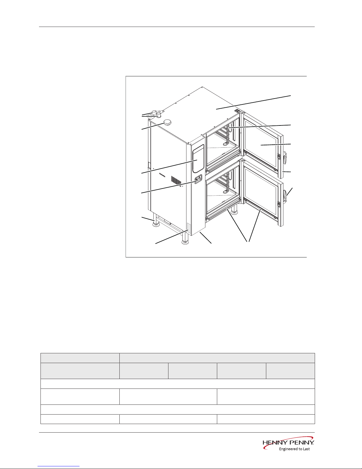
3.1 Overview of the unit
a
j
i
h
g
f
e
d
c
b
m
l
k
Image: Floor-standing unit
a Housing h Nameplate
b Support rack i Equipment leg
c Insulated window j Hand shower
d Cooking zone door k Control unit
e Door handle l Air inlet
f Steam drain channel m Steam outlet
g USB port (covered)
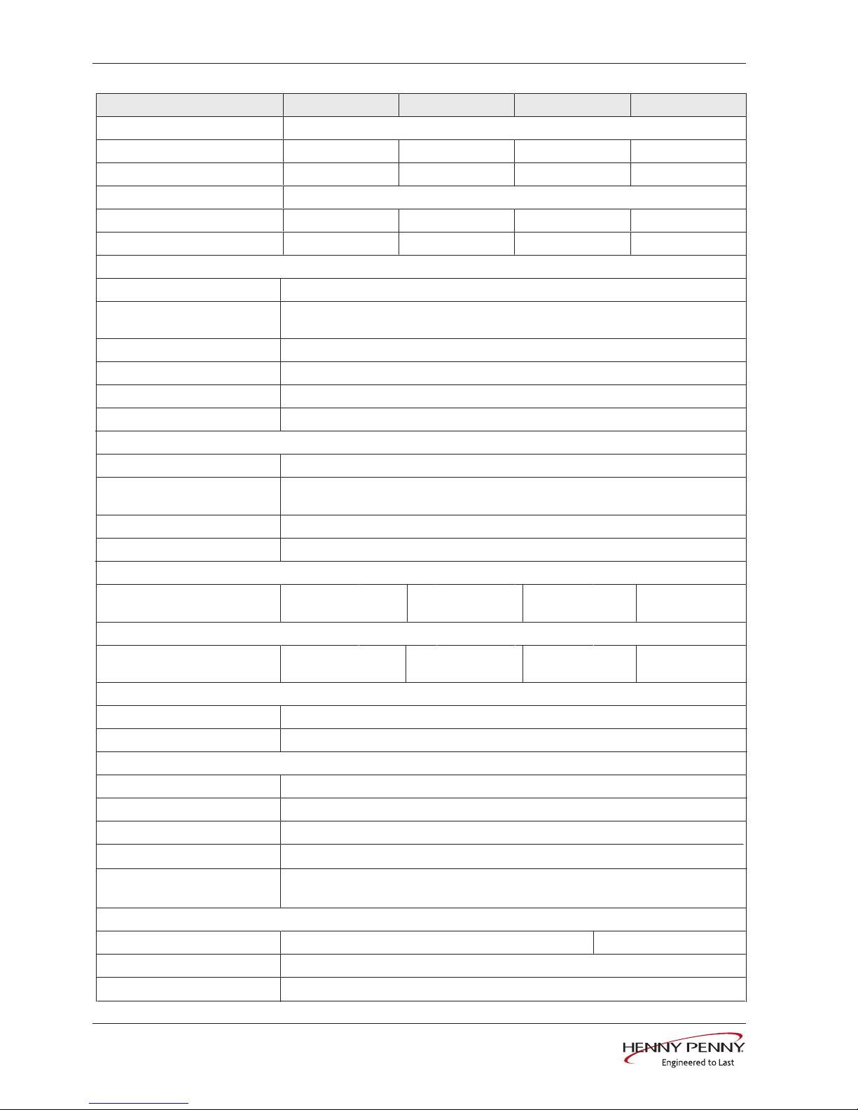
3.2 Equipment and connection data
Model FPED
Size 615-615
615-621
621-621
621-615
115-615
115-621
121-615
121-621
Dimensions
Unit Length x Width x Height
(mm(in))
997 (39,25) x 799 (31,46) x1700 (66,93) 997 (39,25) x 799 (31,46) x1900 (74,80)
Weight
Unit (kg (lb)) 253 (557,77) 291 (641,55)
FM05-253

Description of the unit
11Installation instructions
Size 615 621 115 121
Emissions
Latent heat (W) * 1780 3670 2750 5400
Sensible heat (W) 1190 2450 1840 3600
Noise level (db (A)) < 70
* The stated value is reduced by 80% when operating with a condensation hood; the sensible heat is increased by the
amount of the reduction.
The sensible and latent heat amounts are determined in Germany on the basis of VDI 2052 at a connection voltage of
400V. The applicable regional regulations may vary from this.
Operating environment
Temperature (°C (in)) 5 (42) — 40 (104)
Relative humidity (%)
Non-condensing
95
Power connection
Protection class IPX5
Type of connection 3NPE / AC 50/60 Hz, 3PE / AC 50/60 Hz
Voltage (V) 200
Connected load (kW) 10.1 16.3 14.7 25.5
Fuse (A) 3 x 35 3 x 50 3 x 50 3 x 80
Voltage (V) 208
Connected load (kW) 10.2 17.4 15.7 27.3
Fuse (A) 3 x 35 3 x 50 3 x 50 3 x 80
Voltage (V) 220
Connected load (kW) 11.6 19.7 17.7 30.8
Fuse (A) 3 x 35 3 x 63 3 x 63 3 x 100
Voltage (V) 230
Connected load (kW) 12.6 21.4 19.3 33.6
Fuse (A) 3 x 35 3 x 63 3 x 63 3 x 100
Voltage (V) 240
Connected load (kW) 13.7 23.3 21 36.5
Fuse (A) 3 x 35 3 x 63 3 x 63 3 x 100
Voltage (V) 380
Connected load (kW) 9.4 18.9 14.4 27.6
Fuse (A) 3 x 16 3 x 35 3 x 25 3 x 50
Voltage (V) 400
Connected load (kW) 10.4 20.9 15.9 30.5
Fuse (A) 3 x 16 3 x 35 3 x 25 3 x 50
Voltage (V) 415
Connected load (kW) 11.2 22.5 17.1 32.8
Fuse (A) 3 x 16 3 x 35 3 x 25 3 x 50
FM05-253
Description of the unit
12 Installation instructions
Size 615 621 115 121
Voltage (V) 440
Connected load (kW) 10.4 20.9 15.8 30.5
Fuse (A) 3 x 16 3 x 35 3 x 25 3 x 50
Voltage (V) 480
Connected load (kW) 12.3 20.9 18.9 32.6
Fuse (A) 3 x 16 3 x 35 3 x 25 3 x 50
FM05-253
Softened drinking water connection
Type of water Softened drinking water, cold
Carbonate hardness CaCO
3
(mmol/l (ppm))
< 0,9 (90 ppm)
Chloride Cl (mg/l) < 50
Iron Fe (mg/l) < 0.1
Connection pressure (kPa (psi)) 200 (29) — 600 (87)
Connection (") R 3/4
Drinking water connection
Type of water Drinking water, cold
Carbonate hardness CaCO
3
(mmol/l (ppm))
< 4 (400 ppm)
Connection pressure (kPa (psi)) 200 (29) — 600 (87)
Connection (") R 3/4
Water consumption for steaming
Softened drinking water (l/h
(gal/h))
16 (4,23) 21 (5,55) 18 (4,76) 24 (6,34)
Water consumption for combisteaming
Softened drinking water (l/h
(gal/h))
3,5 (0,92) 4,6 (1,22) 4 (1,06) 5,3 (1,4)
Water consumption for WaveClean cleaning program
Softened drinking water (l (gal)) 3 l (0,79)
Drinking water (l (gal)) 32 l (8,45)
Waste water connection
Waste water type Dirty water, maximum 80 °C (176 °F)
Connection to unit (mm (in)) 50 (1,97)
Maximum length (m (ft)) 1 (3,3) with a drop of at least 5% or 3°
Temperature-resistant to (°C(°F)) 95 (203 )
Maximum flow rate (l/min (gal/
min))
10 (2,64)
Exhaust air connection
Connection to unit (mm (in)) 53 (2,09) 73 (2,87)
Maximum length (m (ft)) 2,5 (8,2)
Temperature-resistant to (°C(°F)) 180 (356)
Description of the unit
13Installation instructions
Transformer voltage
Type of connection 3NPE / AC 50/60Hz, 3PE / AC 50/60Hz
Voltage range (V) 200 — 240
Transformer T1
Marking or colour of the cores Blue Red
Voltage measured (V) Voltage at the transformer (V)
190 — 200 0 200
201 — 220 0 220
221 — 230 0 230
231 — 240 0 240
241 — 250 0 250
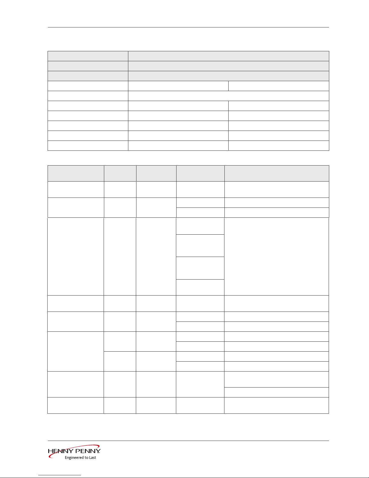
Basic control setting
Basic setting ParametersStandard
value
Adjustment
range
Explanation
Actual voltage 14 400 100 — 500V Set the local, mean voltage between the
line conductors.
Date/time yyyy - mm - dd Year - Month - Day
hh : mm Hour : Minute
FM05-253
ft) the closest weather station. If the altitude
is unknown, set 0—999 m (3277 ft).
1000 m (3280
ft)—1999 m
(6557 ft)
2000 m (6560
ft)—2499 m
(8197 ft)
2500 m (8200 ft)
or higher
Volume of audible
signal
33 Medium Individual Sets the volume.
Unit of temperature 1 °C °C Celsius (°C)
°F Fahrenheit (°F)
Unit of volume 34 ml (ml) Millilitre (ml)
(fl.oz.) Fluid ounce (fl.oz.)
35 Imperial
(fl.oz.)
Imperial (fl.oz.) Imperial fluid ounce
U.S. (fl.oz.) U.S. fluid ounce
Water filter
maintenance
44 0 0 — 99900 l
(26393,66 gal)
Water quantity up to the maintenance
message.
0 = No maintenance message
Network DHCP Network address
and DHCP
Select and set interface.
0—999
2
Altitude
0 - 999 m (3277
Description of the unit
14 Installation instructions
Basic setting ParametersStandard
value
Adjustment
range
Explanation
Kitchen management
system
Disabled Active Port and unit address can be set.
Disabled
Ethernet Ethernet Type of signal transmission
Serial
80% power 3 100 80 % Power can be limited to 80% (for special
applications).
100 %
Power optimisation
system
42 Off On If a power optimisation system is
connected, "On" must be selected for the
unit to heat.
Off
Settings parameters 1. Set parameters via the roller.
2. Tap the "Read" button to display the
set value.
3. Specify another value via the button
panel.
4. Press the "Write" button to save the
new value.
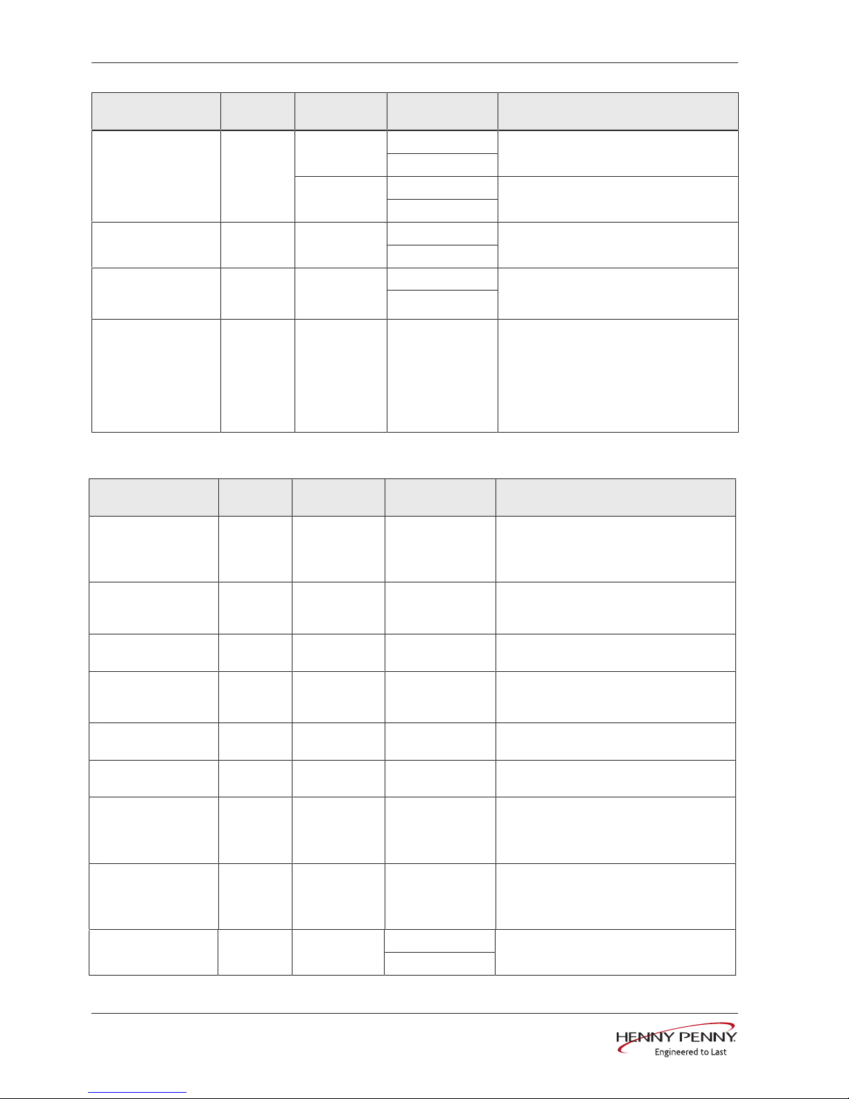
Basic control setting (Advanced)
FM05-253
Basic setting ParametersStandard
value
Range of
adjustment
Explanation
Preheating
temperature
Ready2Cook
4 15 0 — 30% When loaded a full charge of large masses
(roasts, loaf of bread), increase the
preheat temperature so that the oven
temperature does not drop too suddenly.
Condensation-hood
after-running time
5 60 0 – 600 s Time extension for the condensation hood,
after the cooking chamber door has been
opened
Preselected steaming
temperature
9 100 30 °C (86 °F) —
130 °C (266 °F)
Preset temperature for steaming
Preset
combisteaming
temperature
10 150 30 °C (86 °F) —
250 °C (482 °F)
Preset temperature for combisteaming
Preset hot air
temperature
11 180 30 °C (86 °F) —
300 °C (572 °F)
Preset temperature for hot air
Preset regeneration
temperature
12 130 30 °C (86 °F) —
180 °C (356 °F)
Preset temperature for regeneration
Maximum waiting
time after
Ready2Cook for T <
250 °C (482 °F)
37 120 0 — 300 min Maximum waiting time after reaching the
Ready2Cook temperature, for set value <
250 °C (482 °F)
Maximum waiting
time after
Ready2Cook for T >
250 °C (482 °F)
38 30 0 — 60 min Maximum waiting time after reaching the
Ready2Cook temperature, for set value >
250 °C (482 °F)
Time format 675 0 0 = 24 h Set the 12-h or 24-h time format
1 = 12 h
 Loading...