

Page 1

MSM 12
Mobile Rope Load Measurement
Manual
for sensors LSM 1, LSM 2 , LSM XL, LSM 2000
LSM Belt
Page 2

Henning GmbH & Co. KG page 2 19/02/2019
Copyright
© Copyright 2018 by Henning GmbH & Co KG, Loher Str. 4, 58332 Schwelm
Warranty
This manual has been drawn up by Henning GmbH & Co. KG to the best of their knowledge. All
technical statements have been carefully established an checked. They correspond to the state of
the art. Subject to changes and errors.
Our application engineering advice – orally as well as in writing – shall support your ownwork. Please
regard it as an indication without obligation, also with regard to possible third party industrial property
rights, and does not release you from your own obligation to carry out appropriate testing of the
products regarding their suitability for the intended application.
Product descriptions do not contain statements about liability for possible damages. However, should
the case occur, liability will be limited to the value of the goods supplied and utilized.
We are welcoming suggestions and comments!
Address
Henning GmbH & Co. KG
Loher Str. 4
58332 Schwelm
Deutschland
FON: 02336 / 9 29 8 – 0
FAX: 02336 / 9 29 8 – 100
eMail: [email protected]
URL : http://www.henning-gmbh.de
Service-Hotline: 02336 / 9 29 8 - 232
Any kind of duplication, even in extracts, is not permitted without previous written consent
of Henning GmbH & Co. KG.
Subject to technical modifications!
Page 3

Henning GmbH & Co. KG page 3 19/02/2019
Table of Contents
1 Safety and Shipping Instruction 4
2. Scope of Delivery 4
2.A. Optional Equipment 4
2.B. Optional Software 4
3. Control Elements 5
4. Technical Data 5
5. List of Available Sensors 6-7
6. Operating the Evaluation unit MSM12 8
6.A. Charging the Batteries 8
6.A.1 USB-Adapter 8
6.A.2 QI-Ladung 8
6.B. Starting the Device 9
6.C. Main Display 10-11
6.C.1 Sensor Information 12
6.D. Choosing Suspension Type 13
6.E. Saving Data 13
6.E.1 Save actual sensor results-snapshots 13
6.E.2 Continuous Measurements (optional) 14
6.E.3 Allocation of project-ID 15
6.F Configuration 16
6.F.1 Unit Info 17
6.G Rope Adjustment Wizard 17-18
6.H Special Functions 19
6.H.1 Continuous Measurements (optional) 19
6.H.2 Counterweight Compensation 19-20
6.H.3 SyncMaster 21
6.I Bluetooth Connection with PC 21-23
6.J Bluetooth Connection with Android Smartphone 24
7. Operating the Sensors 25
7.A. General Notes 25
7.A.1 Positioning of Sensors on the Rope 26-28
7.A.2 Positioning of Sensors depending on Suspension Type 29
7.A.3 Rope Adjustment 29
7.A.4 Friction / Determination of Weight 29
7.B Installation of Sensors LSM1 und LSM2 30-31
7.C Installation of Sensors LSM-XL 32-33
7.D Installation of Sensors LSM-BELT 34
Page 4

Henning GmbH & Co. KG page 4 19/02/2019
1 Safety and Shipping Instruction
The Evaluation units MSM12 V3 are equiped with lithium - ion batteries.
Safety Instructions
Lithium-ion batteries react violently when coming into contact with water
(fully charged ones in particular)
Do not store Li-Ion batteries near combustible material
Do not overcharge Li-Ion batteries
Do not short-circuit Li-Ion batteries
Li-Ion batteris are sensitive to mechanical damage. After internal short-circuiting and
contact with air they may be highly combustible (even 30 minutes after the actual short
circuiting).
Shipping Instructions
The batteries contained in the evaluation units MSM 12 comply with UN 3481, li-ion batteries contained in equipment (UN-regulations governing the shipment of lithium batteries of
1st January 2009). Please observe special restrictions in connection with li-ion batteries,
especially regarding airfreight and / or request appropriate information from your logistics
partner before shipping.
2 Scope of Delivery
1x mobile evaluation unit MSM12
Version Basic, Extended or Premium
1x USB-connection cable
1x charger 230V
2.A Optional Equipment
Qi-Charger Order Code 455097
USB-Charger Order Code 455096
Protection Bag Order code 455099
2.B Optional Software
Curve Storage
Measures and stores the rope tensions / individual weights during the ride e.g. to allow sets
of ropes to be optimized later. Order Code 455155
Counterweight Compensation Measurement
Assistant allowing counterweight compensation to be simplified without the use of weights
or additional tools, storage and preparatopn of reports for future documentation.
Order Code 455160
Page 5
Henning GmbH & Co. KG page 5 19/02/2019
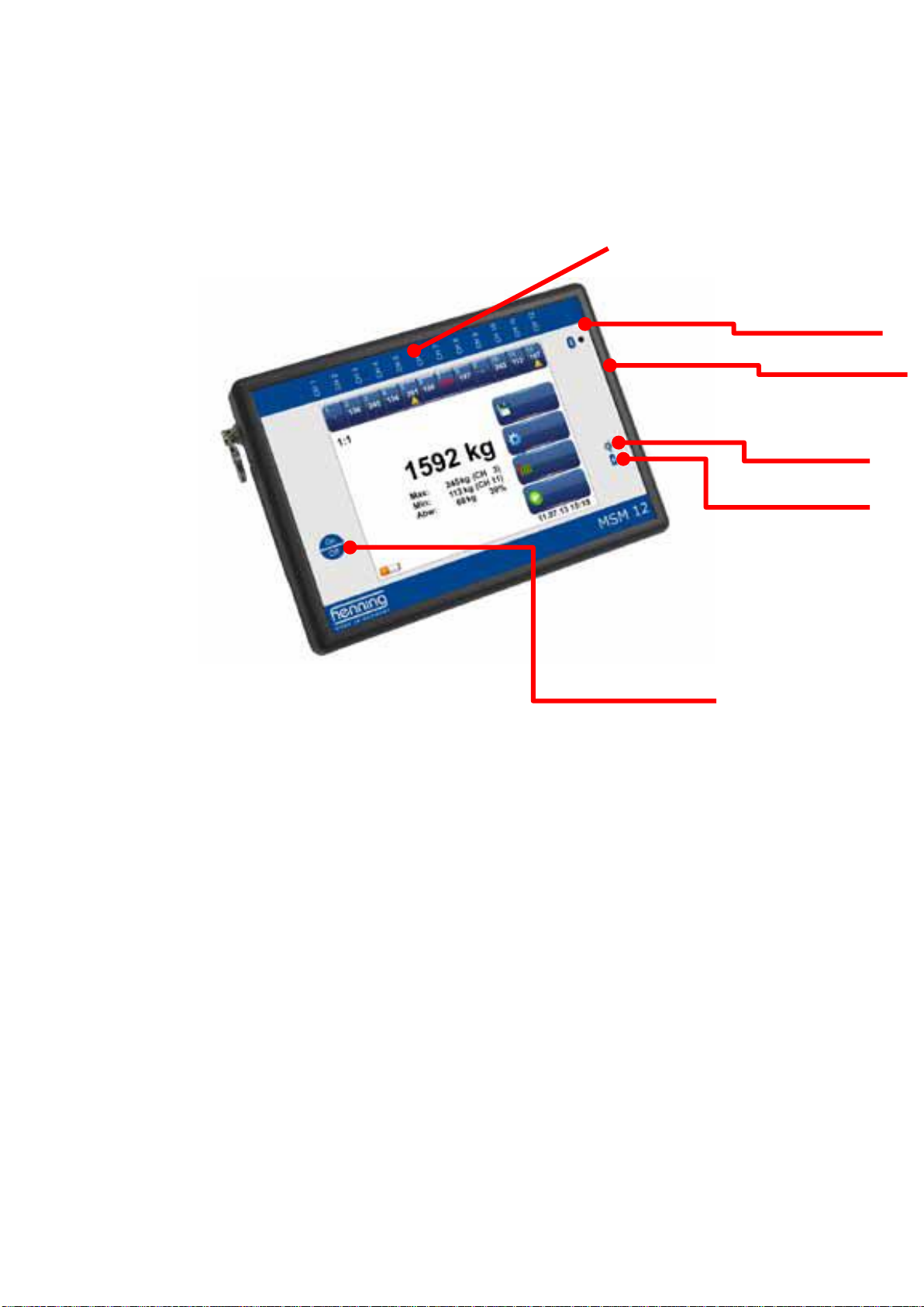
3 Control Elements
Connections for rope load
sensors
4 Technical Data
Power is supplied by internal lithium-ion batteris with a capacity of 4,5 AH (Basic), 6,75 AH
(Premium) oder 9 AH (Extended).
Sensor Connections: 12
Bandwidth: 30 Hz
Sample frequency: 100 Hz
Connections: USB, BlueTooth (optional)
Protection Class: IP00 SKIII (SELV)
L x W x H (mm): 190 x 138 x 46
Weight: 650 g
Antenna socket (optional)
Bluetooth activity indicator
Charge indicator
QI-charge activity indicator
On / Off switch
Page 6
Henning GmbH & Co. KG page 6 19/02/2019
5 List of available Sensors
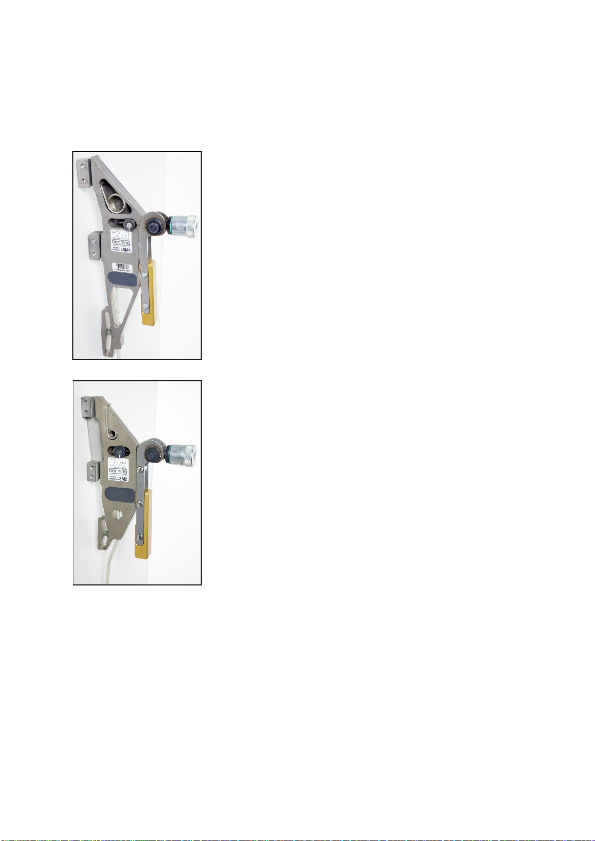
Mobile Rope Load Sensor LSM 1
(6 - 16 mm, ¼ inch – 5/8 inch)
For Rope Diameters 6 mm - 16 mm
1
/4 inch – 5/
8
inch
Measuring Range 0 - 500 kg (± 2,5% FSR),
0-1100 lbs (± 2,5% FSR)
Maximum Load 1000 kg, 2200 lbs
Breaking Load 2000 kg, 4400 lbs
L x W x H (mm) 250 x 75 x 19
Length of
Connecting Cable 0,8 m, 31,5 inch
Temperature Range 0 °C - 70 °C
Mobile Rope Load Sensor LSM 2
(4 - 10 mm) (3/16 inch – 3/8 inch)
For Rope Diameters 4 mm - 10 mm (
3
/16 inch – 3/
8
inch)
Measuring Range 0 - 300 kg (± 2,5% FSR),
0-660 lbs (± 2,5% FSR)
Maximum Load 600 kg, 1320 lbs
Breaking Load 1200 kg, 2640 lbs
L x W x H (mm) 178 x 58 x 16
Length of
Connecting Cable 0,8 m, 31,5 inch
Temperature Range 0 °C - 70 °C
Page 7
Henning GmbH & Co. KG page 7 19/02/2019
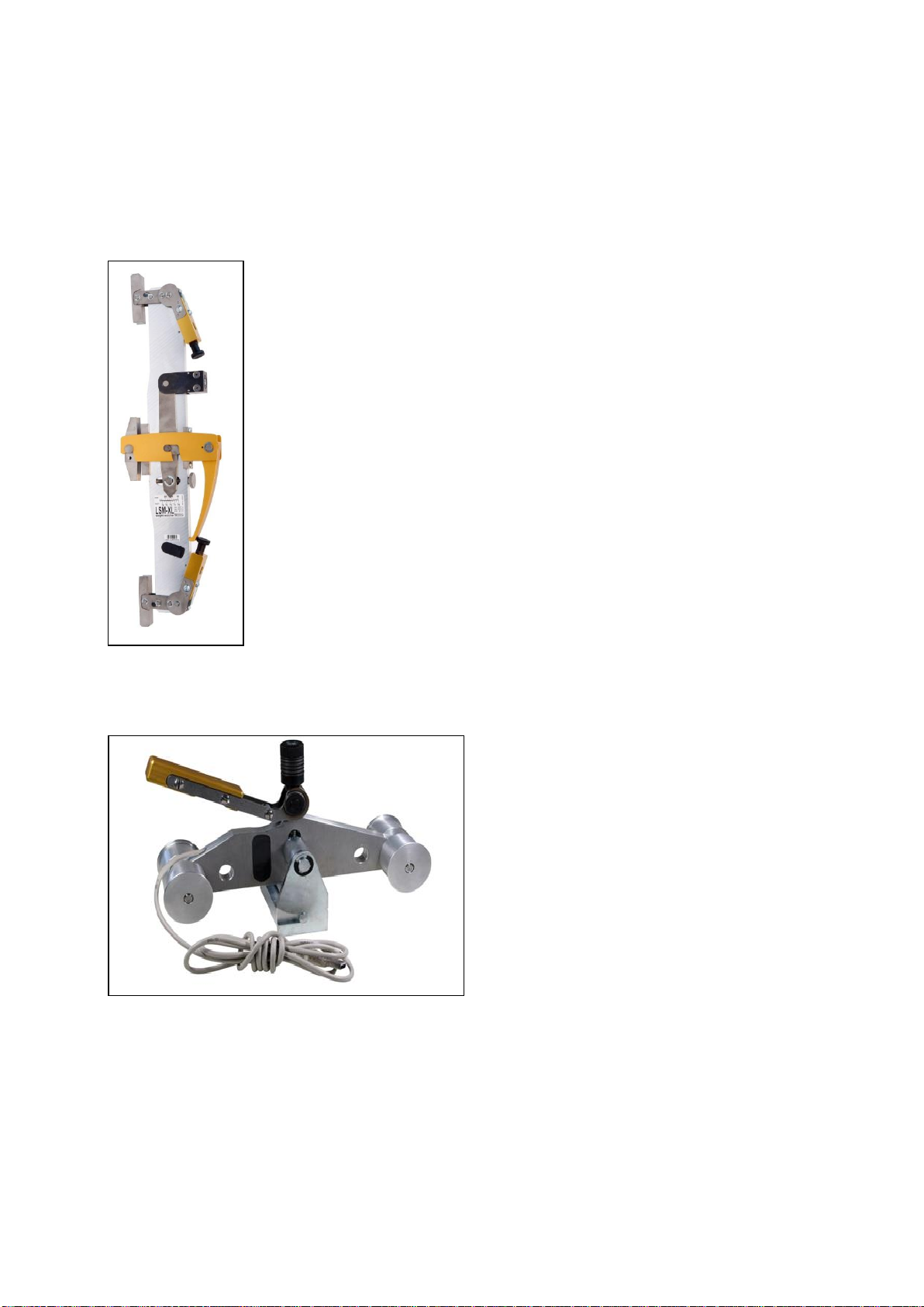
Mobile Rope Load Sensor LSM-XL (9,5 - 24 mm) (3/8 inch – 15/16 inch)
For Rope Diameters 9,5 mm – 24 mm
(3/8 inch – 15/16 inch)
Measuring Range 200 - 2000 kg (± 2,5% FSR),
400-4500 lbs (± 2,5% FSR)
Maximum Load 4000 kg, 9000 lbs
Breaking Load 6000 kg, 13500 lbs
L x W x H (mm) 570 x 210 x 50
Length of Connecting Cable 1,5 m, 59 inch
Temperature Range 0 °C - 70 °C
Mobile Rope load Sensor LSM-Belt
For Belts 30 mm and 60 mm
Measuring Range 0 - 500 kg
(± 2,5% FSR),
0-1100 lbs (± 2,5% FSR)
Maximum Load 1000 kg, 2200 lbs
Breaking Load 2000 kg, 4400 lbs
L x W x H (mm) 230 x 120 x 82
Length of
Connecting Cable 0,8 m, 31,5 inch
Temperature Range 0 °C - 70 °C
Page 8

Henning GmbH & Co. KG page 8 19/02/2019
6 Operating the Evaluation unit MSM12
Generel Advice
Please protect the evaluation unit MSM12 against dust, moisture and impact. We recommend the optional protection case made from padded cordura, incorporating a large transparent window.
Protection Bag Order Code 455099
6.A Charging the Batteries
When switched on, the main screen shows the batterie’s current state of charge. Please
charge the batterie as soon as the battery status changes to red status. During charging,
the charge control changes to continuously red light.
Important notice: Please switch the unit off while charging, as otherwise most of the
energy will be used up for the operation of the unit.
6.A.1 USB-Adapter
For charging via USB-connection, please connect the MSM12 with the USB-cable to the
charging adapter and connect the adapter to the main power supply. Charging will take,
depending on the state of the batteries, between 9 and 18 hours.
6.A.2 Qi-Charging
For charging via Qi-interface, please connect the Qi-charger to the USB charging adapter.
Place the evaluation unit MSM12 onto the center of the charger, main screen facing away
from the charger. If positioned correctly, the charge control will change into active mode and
the Qi-charge indicator will be activated after ca. 2 seconds. Charging will take up to 9 hours.
Page 9

Henning GmbH & Co. KG page 9 19/02/2019
6.B Starting the Device
In order to switch on the MSM12 mobile rope load meter please press the on/off switch for
a minimum of 3 seconds. The display now shows the Weight Watcher logo as well as a
progress bar. After a short time the display switches over to the main display. The MSM12
is now ready for operation.
To switch off please press the on/off switch for minimum 3 seconds again. The device
switches off and the display lighting is extinguished. If the batteries are run-down, the
MSM12 switches off automatically.
Page 10
Henning GmbH & Co. KG page 10 19/02/2019
6.C Main Display
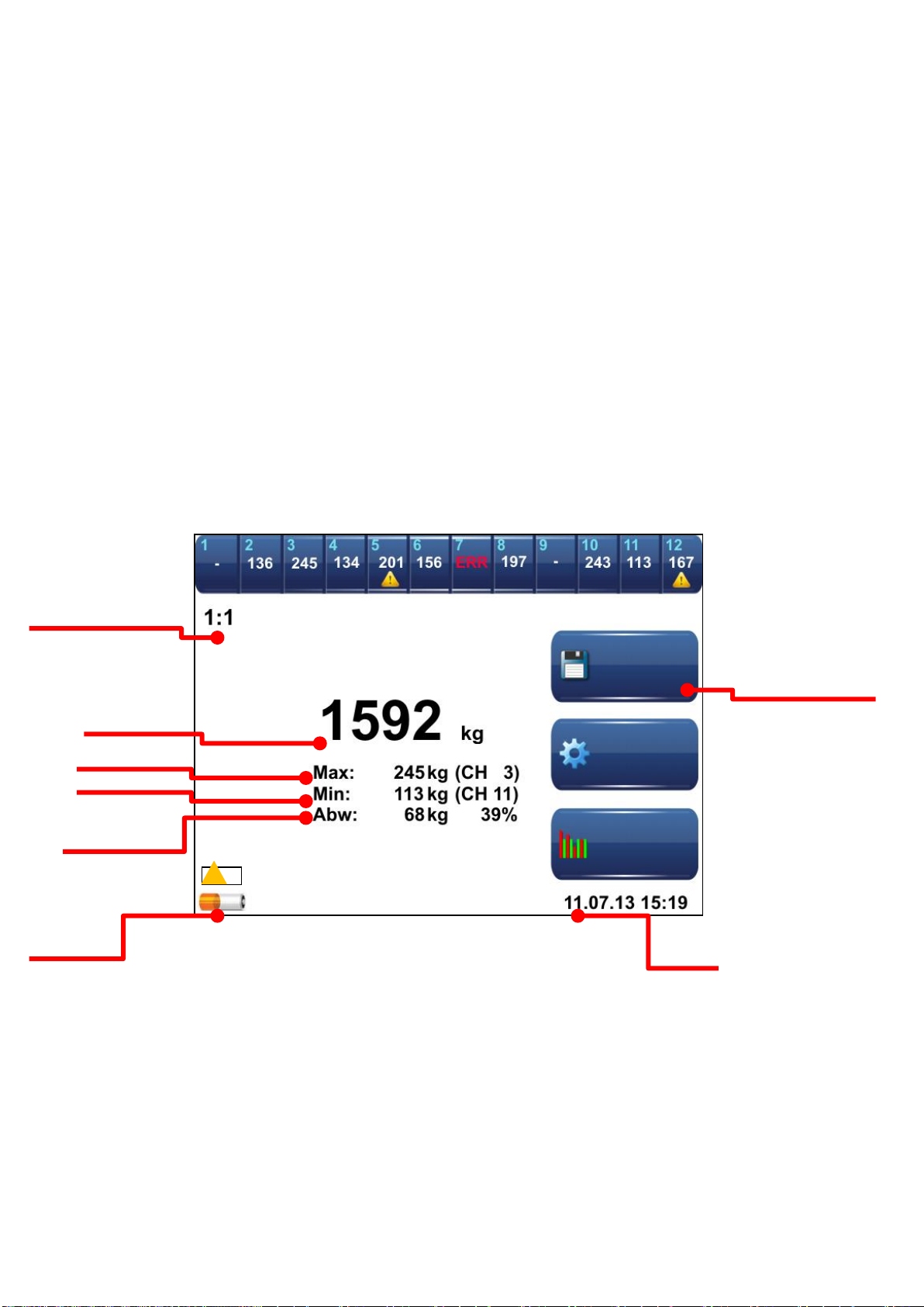
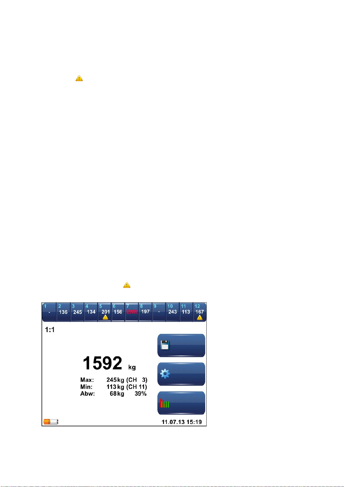
Below, the main display of the mobile rope load evaluation unit MSM12 is shown. The upper
two lines display the status bar indicating the individual weight of each rope under the corresponding measuring chanel number.
Below, in the centre, the total weight resulting from the individual weights as well as the
maximum individual load, minimum individual load and the maximum deviation and the corresponding measuring channel numbers are indicated. At the right side four menu keys are
to be found which will be described in detail later. In the lower left-hand corner the charge
status of the batteries is displayed. On the upper left below the status bar the selected suspension ratio is shown.
The individual sensor display shows the measured load of each connected rope load sensor.
Please note: The load in the status bar on top will not be calculated on the basis of
the selected suspension ratio.
Selected Suspention ratio
Sensor value 1 to 12 / Status Bar
Total weight
Max. single load
Min. single load
Max. deviation
Current state of
battery charge
Date / Time
Menu keys
Page 11
Henning GmbH & Co. KG page 11 19/02/2019
If a connected sensor is defective, ERR will be displayed. The yellow warningtriangle will show up, as soon as the calibration of the corresponding sensor has
expired.
A touch on one of the sensor-keys in the status bar will open a separate window showing
the data of the corresponding sensor (see also 6.C.1 “sensor-information”).
The suspension ratio of the elevator can be selected manualy by the user. The displayed
total weight is calculated by this factor. The individual weight displayed per sensor remains
unaffected (see also 6.D “Choosing Suspension Type”).
The total weight is the sum of all individual rope loads measured, converted according to
the suspension ratio (if applicable). The output can be selected in different weight units
such as kilogram, tons, Newton, English pounds, short tons or long tons.
The maximum individual rope load shows the actual load and the measuring channel number of the sensor which is loaded with the highest weight in the rope set. The minimum
individual rope load display shows the corresponding information for the rope with the lowest
load.
The maximum deviation shows the deviation (absolute as well as percentage) of the rope
with the greatest deviation from the average calculated from all ropes. The example in figure
shows a total weight of 1,529 kg distributed among nine ropes. This means that under ideal
conditions each rope should carry 177 kg. However, the rope at measuring channel 3 carries
245 kg, i. e. 68 kg (absolute) or 39 % more load(rounding errors possible).
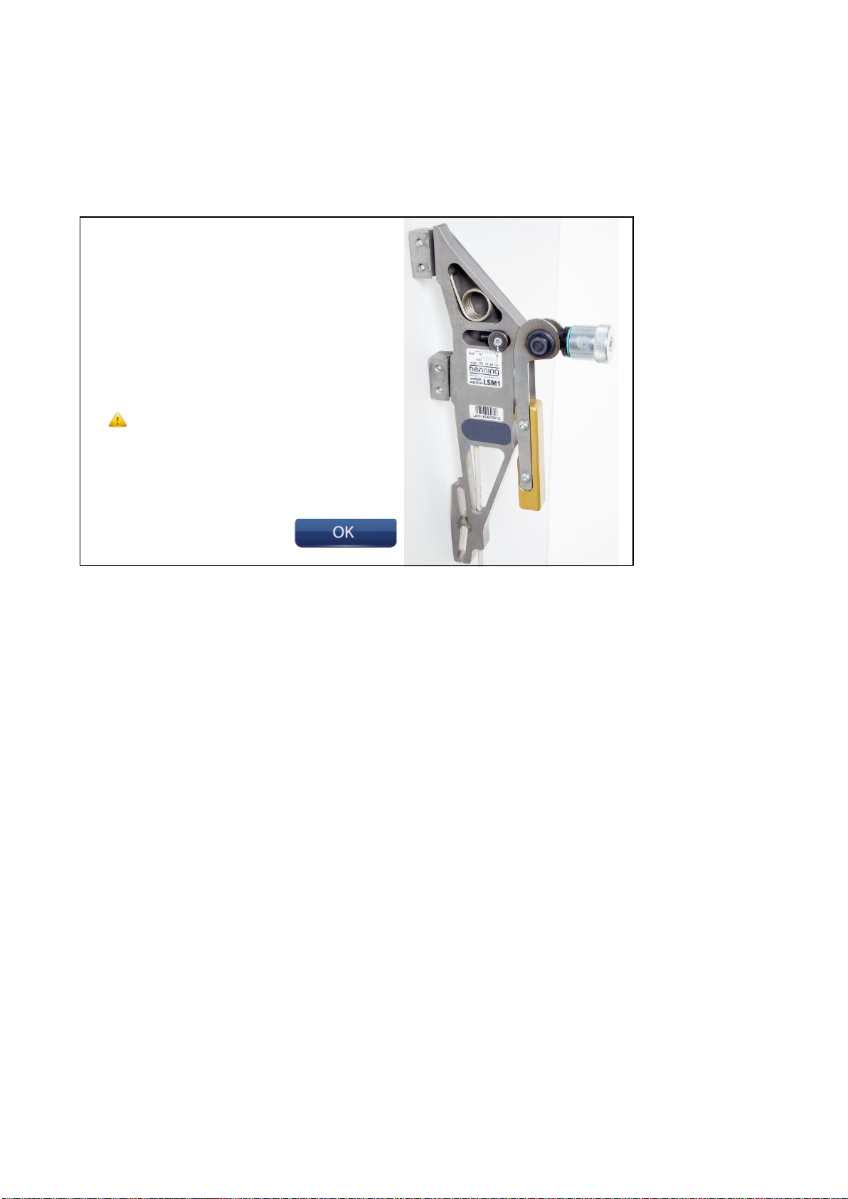
The calibration warning will be displayed, if the last calibration of the evaluation unit
has been one year ago (or longer).
Save
Tensoning
Configuration
Page 12
Henning GmbH & Co. KG page 12 19/02/2019
6.C.1 Sensor Information
For the WeightWatcher mobile system four sensor types for different rope diameters are
available:
- LSM1 diameter 6 mm – 16 mm (1/4 inch – 5/8 inch)
- LSM2 diameter 4 mm – 10 mm (3/16 inch – 3/8 inch)
- LSM-XL diameter 9,5 mm – 24 mm (3/8 inch – 15/16 inch)
- LSM-BELT for belts 30 mm and 60 mm
Sensor type:
LSM 1
Serial no.:
00623459
Last calibration:
15.04.2012
Last Calibration was
more than 365
days ago!
Page 13
Henning GmbH & Co. KG page 13 19/02/2019
6.D Choosing Suspension Type
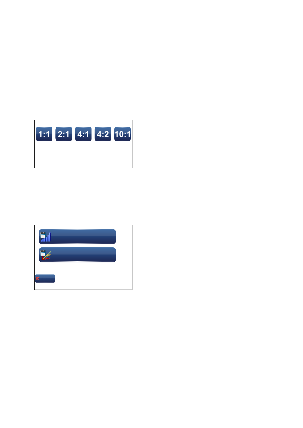
In this menu section one can enter the suspension ratio of the elevator at which you want to
carry out measurements. The ratio is displayed on the main display; however, it is not permanently stored in the evaluation unit. After a restart the evaluation unit will automatically
be displaying a suspension of 1 : 1.
By means of the suspension ratio the displayed total weight is calculated. The suspension
ratio has no influence on the individual rope loads.
6.E Saving Data
By touching the key „save“, a selection menu opens, in which one can choose between the
options “save current weight distribution” and “measurement of load curve”, if you have pur-
chased the optional software “curve storage”. If not, the unit switches automatically to the
allocation of the project-ID (see also 6.E.3).
6.E.1 Save actual sensor result-snapshot
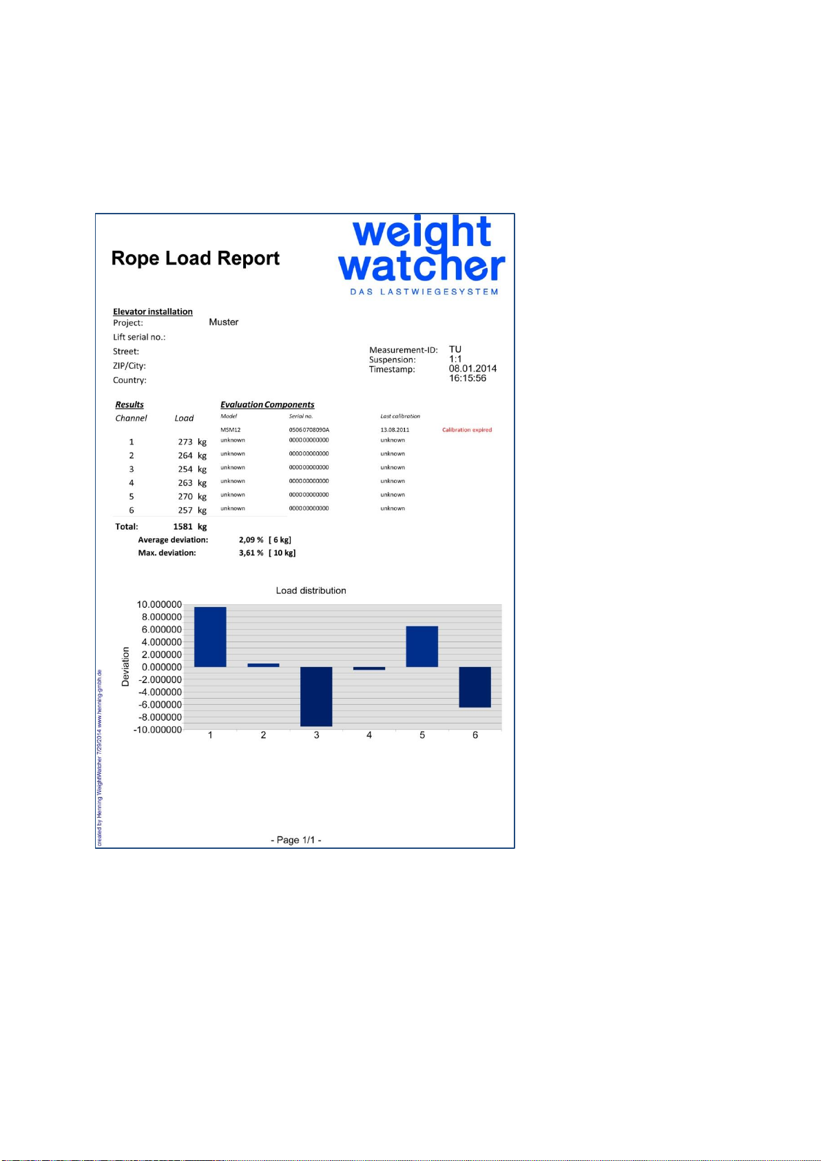
As soon as this key is activated, the data of all connected rope load sensors is evaluated;
the sensor- and load-data is being saved in the evaluation unit. One can allocate a projectID at this point (see also 6.E.3). Reports can be issued via the PC-software.
Cancel
Save actual sensor resultsnapshot
Sample load data
continously
Page 14
Henning GmbH & Co. KG page 14 19/02/2019
6.E.2 Continuous Measurements (optional)
As soon as this key is activated, the data of all connected rope load sensors is evaluated
continuously until the measurement is terminated by pressing the key “save”.
Important Notice: during the measurement no sensors may be removed oder added!
The data is being saved in the evaluation unit via “allocation of project-ID” and reports can
be issued with the PC-software.
Page 15
Henning GmbH & Co. KG page 15 19/02/2019
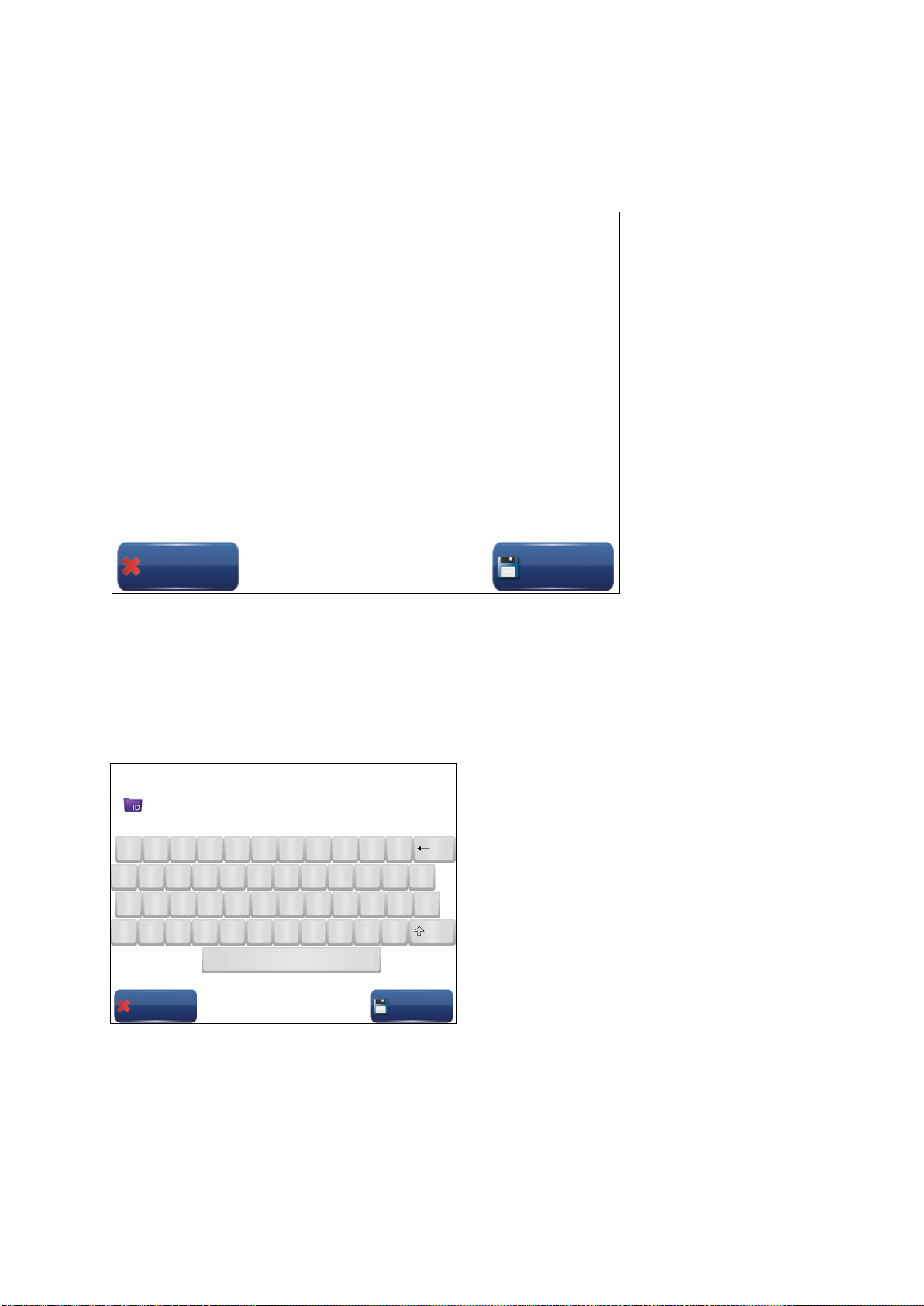
6.E.3 Allocation of Project-ID
The project-ID may consist of up to 16 characters which can be chosen randomly. They help
to identify the project and will be printed on each report created from this particular data.
Save
Cancel
Measurement is running…
Cancel
Save
1 2 3 4 5 6 7 8 9 0 ß
< Y X C V B N M , . -
ID
Page 16
Henning GmbH & Co. KG page 16 19/02/2019
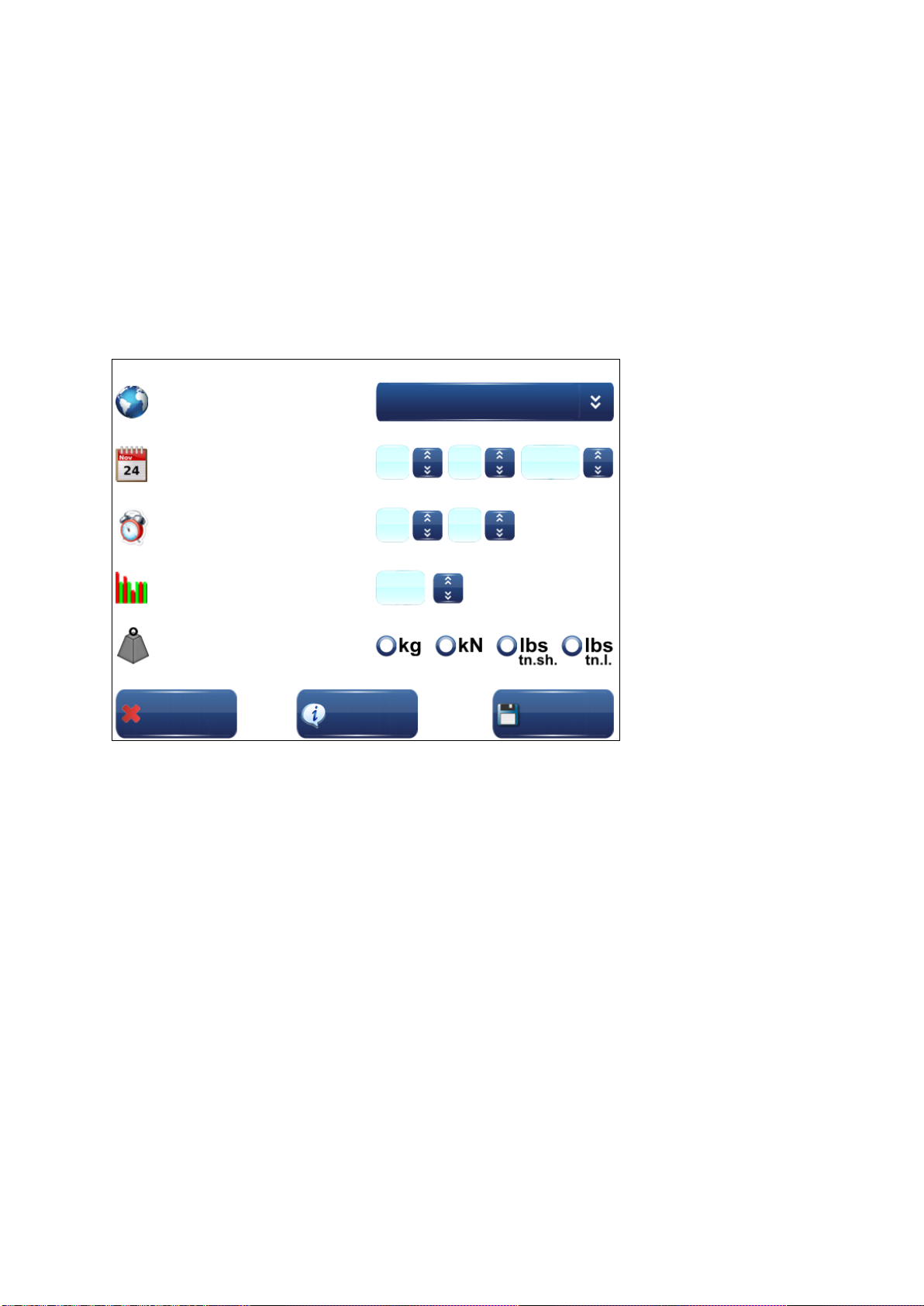
6.F Configuration
The menu „configuration“ is for selecting language, date, time, display settings as well as
tollerances. The latter refers to the tolerance which is valid during rope adjustment. A value
of 5% means, that each rope may vary only by 5% from the theoretical ideal value.
The settings are saved as soon as the key “save” is pressed. If a new language has been
chosen, the unit will reboot automatically. Please see the following chapter for a definition
of the key “Unit Info”.
language
date
time
tensoning tolerance
unit
Cancel
Unit-Info
Save
English
2014
05
06
13
10
5
Page 17
Henning GmbH & Co. KG page 17 19/02/2019
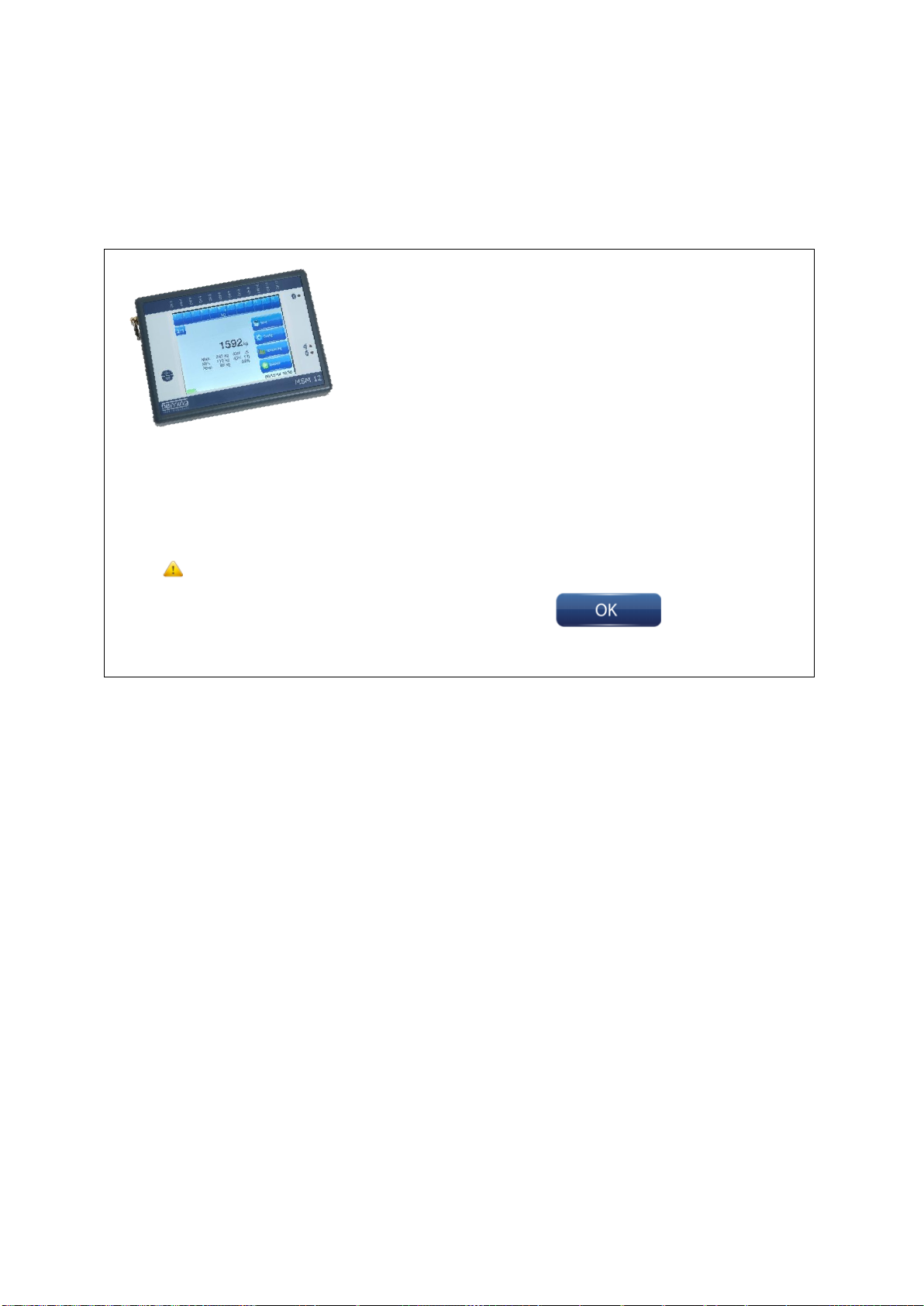
6.F.1 Unit Info
This function shows the user alongside general information like serial number and date the
hard- and software installed on this particular unit as well as the date of the last calibration.
The options “Synchronisation Module” and “Sync-Master” will be available from the year
2015.
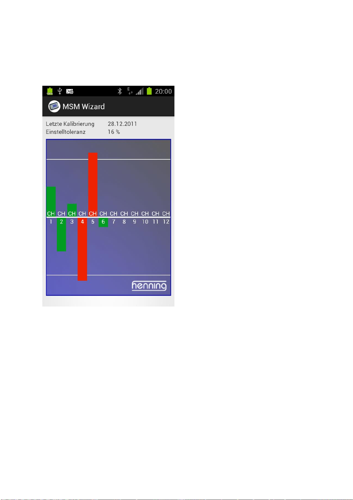
6.G Rope Adjustment Wizard
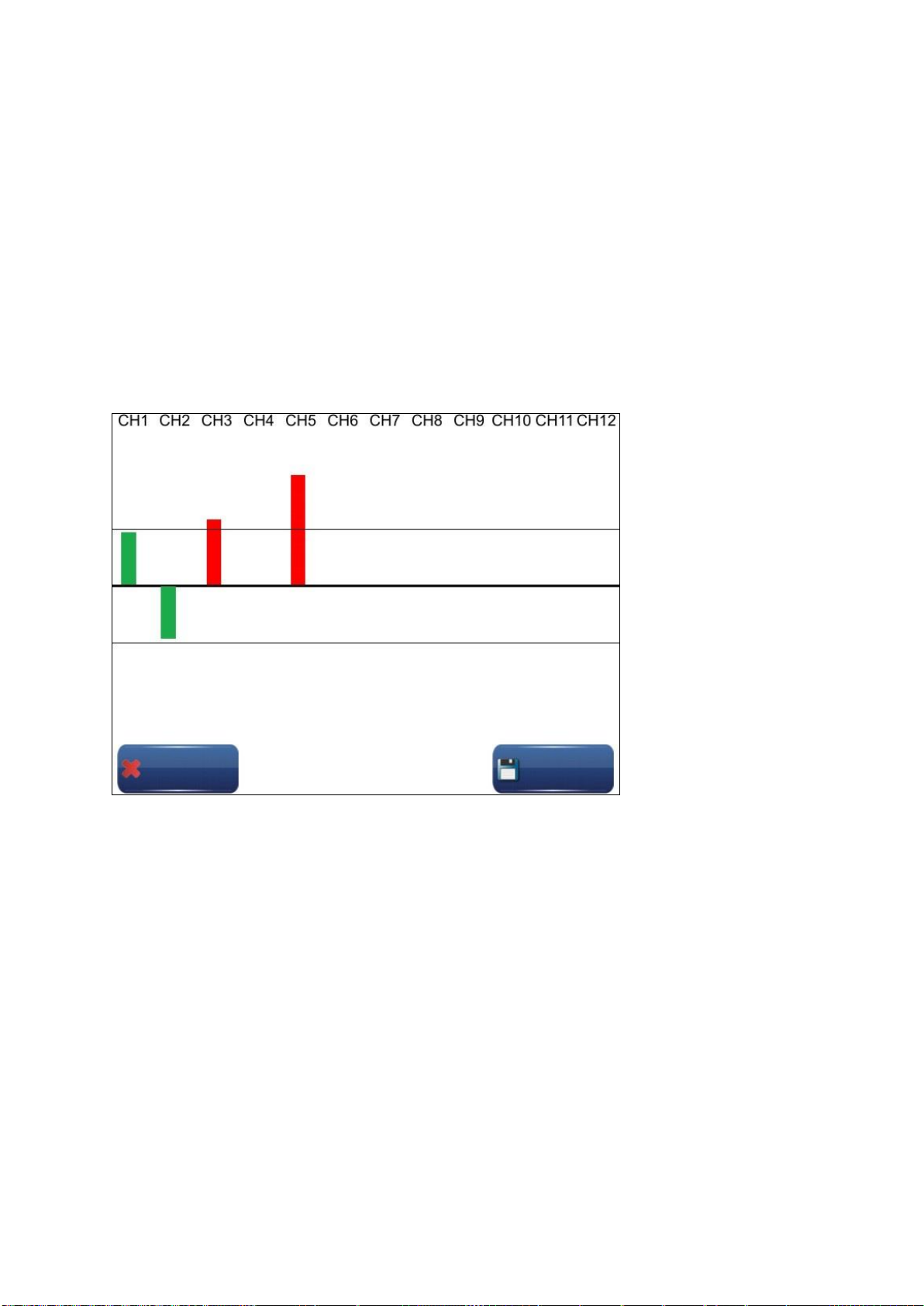
The rope load wizard will assist you with the uniform adjustment of the ropes. For this purpose the wizard uses the current rope loads as the actual state and calculates a new setpoint
load for each rope. The changed load distribution in the ropes is already taken into consideration when readjusting one of the ropes. Due to a special algorithm it will be possible that
all ropes bear the same load after only one adjustment run. Also, during each adjustment
process the wizard determines a reference rope which does not have to be adjusted (rope
4 in the illustration). The rope load wizard will only be activated when two or more sensors
are connected.
Hardware options:
Internal memory 8 GB
Battery charge 4,5 Ah
Bluetooth
QI-charging
Sync-master
Software options:
Curve storage during the ride
Counterweight compensation measurement
Sync-master
Serial no.:
00623459
Last calibration:
15.04.2012
Last Calibration was
more than 365
days ago!
Page 18
Henning GmbH & Co. KG page 18 19/02/2019
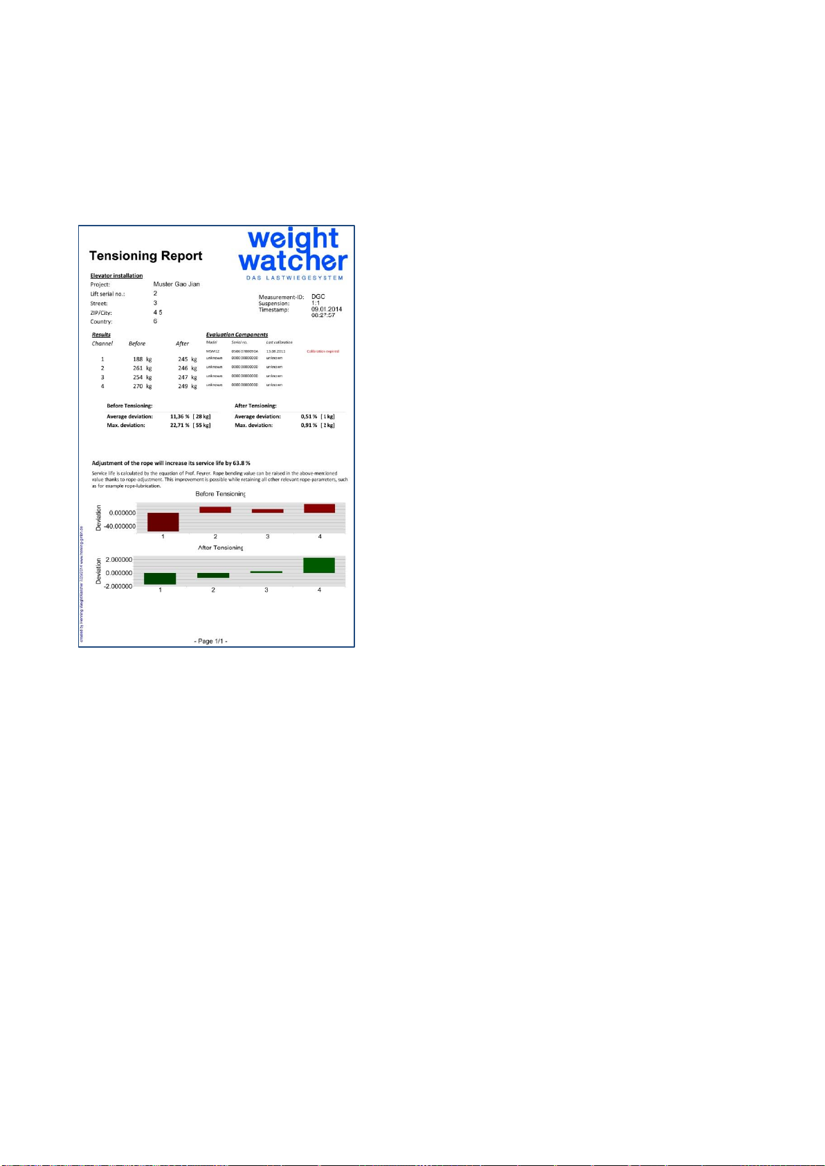
Your goal is to adjust the ropes in such a way, that all bars change their colour from red to
green and settle within the two thin horizontal lines, which define the tolerance, which you
have set in the menu “configuration”. Bars above of the central line represent tense ropes
whereas bars below the centre line represent loose ropes.
As soon as you leave the wizzard by pressing the „save“ key, the data is stored in the unit
and you will be able to allocate a project-ID (see also 6.E.3). Data can be processed utilizing
the PC-software and reports can be issued.
Save
Save
Cancel
Cancel
Save
Cancel
Page 19
Henning GmbH & Co. KG page 19 19/02/2019
6.H Special Functions
In this part of the menu you will find the software-options available in this particular evaluation-unit.
6.H.1 Continuous Measurements (optional)
Please see chapter 6.E.2
6.H.2 Counterweight Compensation (optional)
This software option allows one to determine the counterweight compensation fast and comfortable.
Page 20
Henning GmbH & Co. KG page 20 19/02/2019
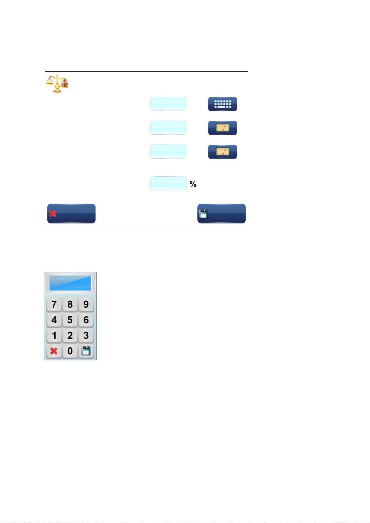
The evaluation unit must be fed the payload of the installation. Please enter it by utilizing
the topmost key. A dialogue box will open; please enter the value and save by pressing the
“disk-key”.
Afterwards, please install the rope load sensors onto the ropes above the car and press the
middle key to determine the weight of the car. Please proceed in the same way with determining the counterweight.
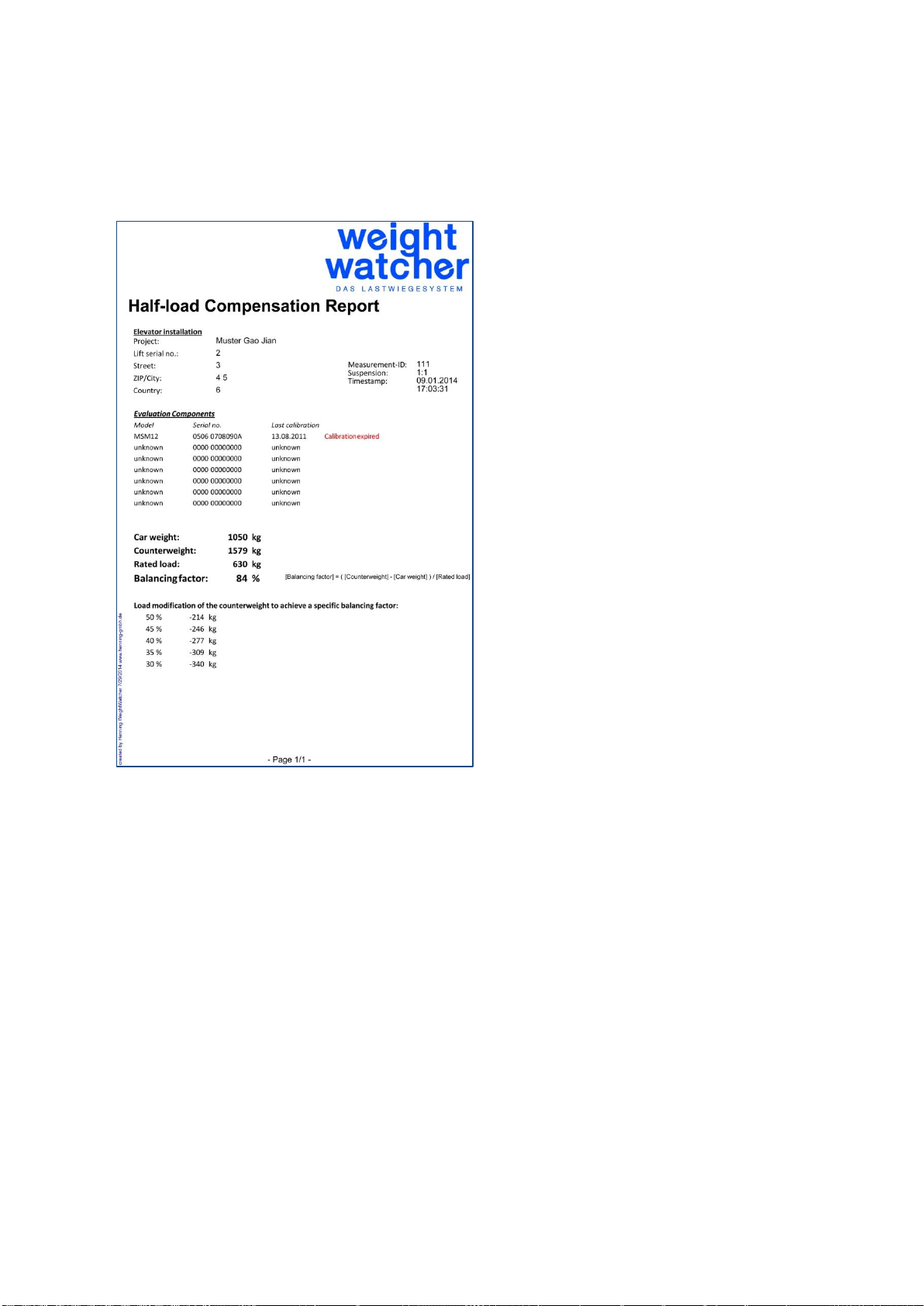
As soon as the unit has been fed all values, the current counterweight compensation will be
shown as a percentage. This factor has been calculated according to the following formula:
[Compensation-Factor] = ([Counterweight] – [Car Weight]) / [Rated load]
As soon as you leave the dialogue by pressing the key “save”, you can allocate an additional
measurement-ID permanently in the unit and issue reports via the PC-software.
Save
Cancel
Rated load
Cabin weight
Counterweight
Compensation factor
Page 21
Henning GmbH & Co. KG page 21 19/02/2019
6.H.3 SyncMaster (optional)
This option will be available in the year 2015
6.I Bluetooth Connection with PC
For the establishment of a wireless Bluetooth connection with the evaluation unit MSM12 a
Bluetooth adapter for your PC is required. If the computer is not equipped with such an
adapter, you can utilize Henning’s optional Bluetooth adapter. Follow the instructions of Win-
dows 7 (and follow up versions) operating system. These instructions will appear as soon
as you have connected the Bluetooth adapter to your computer. Do not use the driver CD!
In exceptional cases, dependent on your PC-configuration, the Bluetooth adapter is not automatically recognized and installed by the system. In such a case use the installation CD
Page 22
Henning GmbH & Co. KG page 22 19/02/2019
supplied by Henning and follow the instructions of the installation program. The operating
instructions of the Bluetooth adapter are also found on the CD.
In order to utilize the wireless connection between the evaluation unit MSM12 and the computer the MSM12 must be logged onto the PC. Please find below a description of the procedure under Windows. For other operating systems the adjustments should be made correspondingly. The evaluation unit MSM12 uses the Bluetooth PIN:
0000
(four times zero).
In order to log on the MSM12 to the computer, please switch it on. For this purpose press
the on / off switch of the device for a minimum 3 seconds. The display should show the
Weight Watcher logo as well as a progress bar.
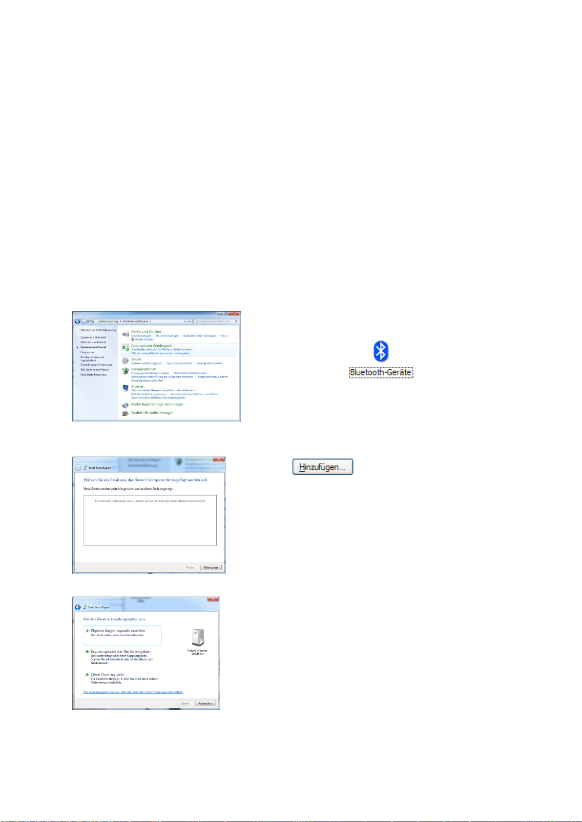
Open the system control. Select “Hardware and
Sounds”.
Search for the icon and open the window
with a double click. Make sure, that the MSM12 has
been switched on.
Click on . [Add…]All available Bluetooth
applications will be listed. Select “”Weight Watcher
MSM12” with a double click.
Select the option „insert interconnection code“ in the di-
alogue box.
Page 23

Henning GmbH & Co. KG page 23 19/02/2019
Please enter the PIN 0000 and click .
[Continue >] to proceed.
The unit will be configured
Close the window by clicking [close] .
The MSM12 rope load meter is now listed as a virtual COM port on your Windows system
and can be utilized like a MSM12 directly connected via USB.
Please note: firmwareupdates are only possible via USB connection.
6.J Bluetooth Connection with Android Smartphone
Search for the Henning Android App with the keyword “MSM-Wizard” in the Google
playstore (http://play.google.com). After installing the app, the wizard will guide you through
the necessary steps for establishing a connection between the evaluation unit MSM12 and
your smartphone / tablet. Please make sure that the MSM12 is switched on and within blue-
tooth-range. Thereafter you will be able to run the rope adjustment wizard on your mobile
device, if the MSM12 is within Bluetooth-range, which will be very usefull for machineroomless elevators.
Page 24
Henning GmbH & Co. KG page 24 19/02/2019
Page 25

Henning GmbH & Co. KG page 25 19/02/2019
7 Operating the Sensors
7.A General Notes
Operation
The rope load sensors are based on a patented measuring method which allows to carry
out absolute measurements without the nned to calibrate the system with weights. The
sensor contains a strain gauge, the signals of which are beeing conditioned by integrated
electronics and transmitted via the USB connector of the sensor to the evaluation unit
MSM12. Each sensor is calibrated individually.
Connections
Each LSM sensor features cable with USB-A connector to connect them to the evaluation
unit MSM12. The sensors have no other connecting options.
Handling
To ensure that there is always good electrical contact please keep the sensor plugs free
from dust, liquids etc..
Page 26
Henning GmbH & Co. KG page 26 19/02/2019
7.A.1 Positioning of Sensors on the Rope
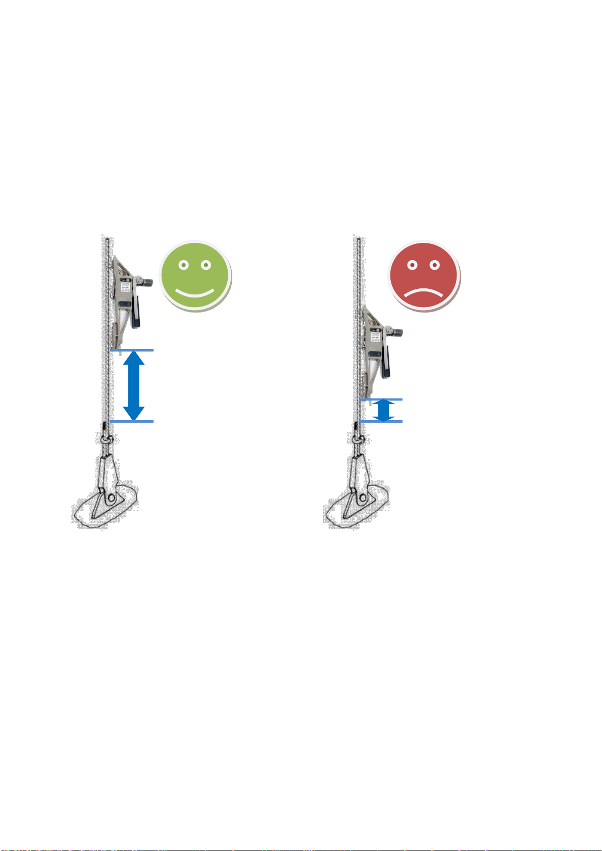
The sensors must be mounted with a minimum clearance of 200 mm to the rope clamps, as
a non perpendicular running cable may distort the result of the measurement.
! Attention: for an accurate measurement, the sensor may be clamped only once onto
a particular space in a rope.
> 200 mm
< 200 mm
Page 27
Henning GmbH & Co. KG page 27 19/02/2019
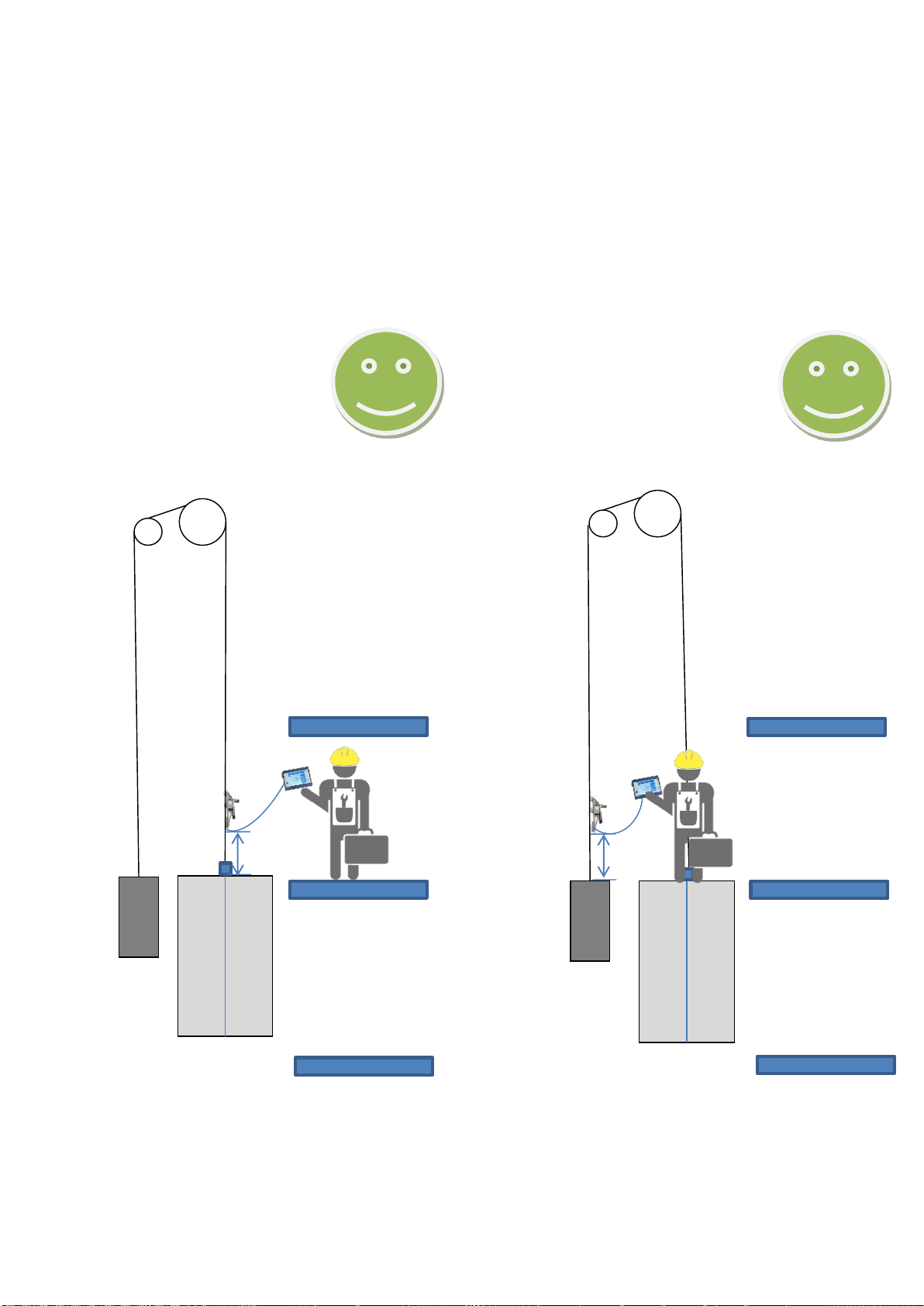
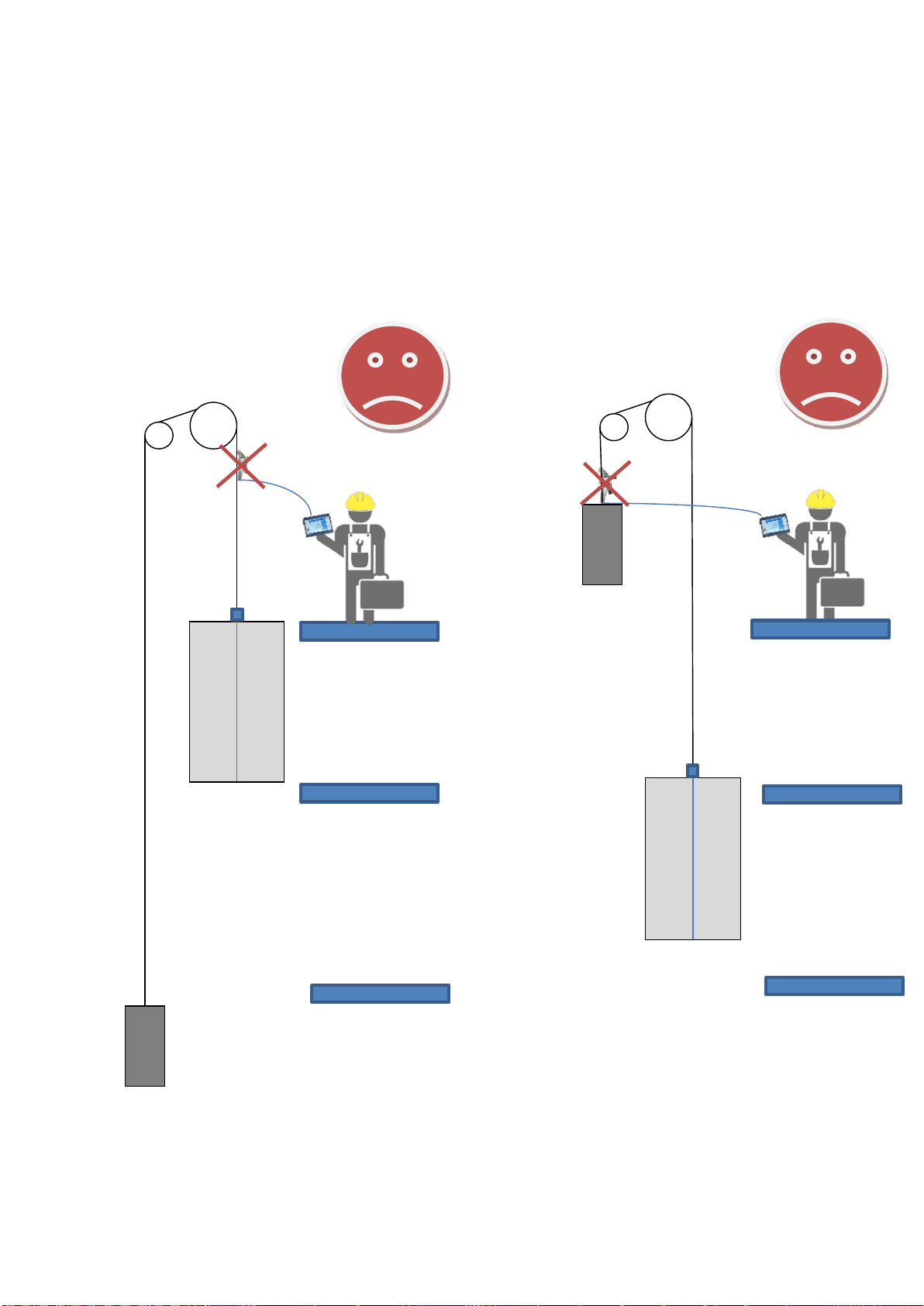
7.A.2 Positioning of Sensors depending on Suspension Type
1:1 Suspension
CABIN
COUNTERWEIGHT
floor
floor
floor
floor
floor
floor
300
mm
300
mm
Page 28
Henning GmbH & Co. KG page 28 19/02/2019
1:1 Suspension
CABIN
COUNTERWEIGHT
floor
floor
floor
floor
floor
floor
Page 29
Henning GmbH & Co. KG page 29 19/02/2019
floor
floor
floor
floor
floor
300
floor
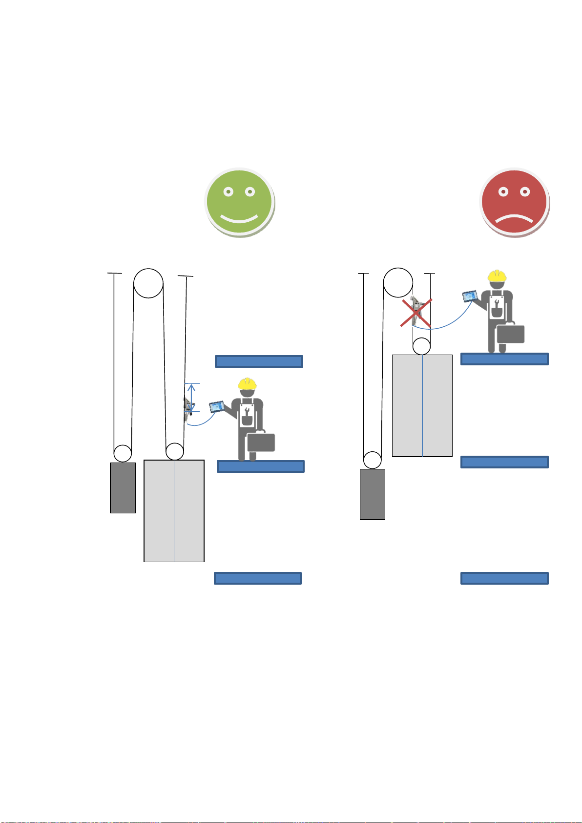
2:1 Suspension
MEASUREMENT CABIN
Page 30
Henning GmbH & Co. KG page 30 19/02/2019
floor
floor
floor
floor
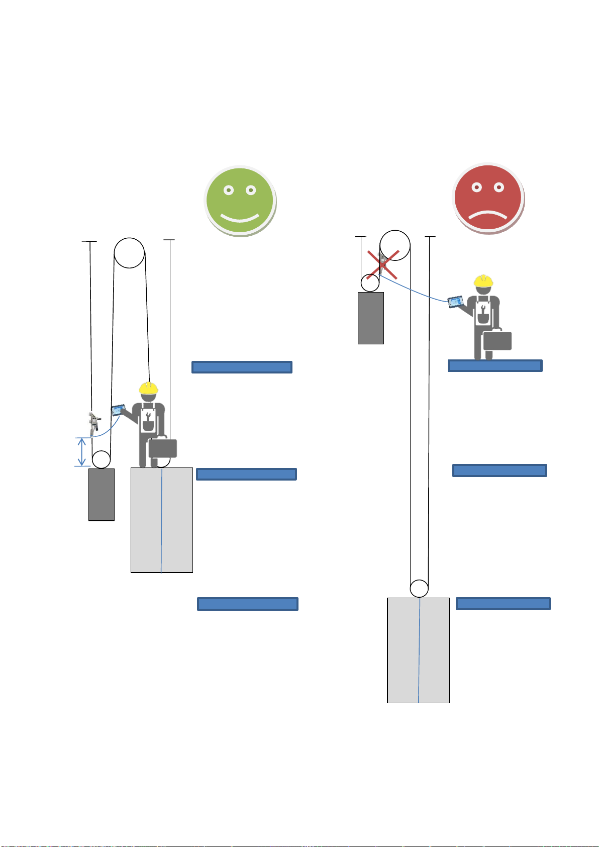
MEASUREMENT COUNTERWEIGHT
floor
floor
2:1 Suspension
300
mm
Page 31
Henning GmbH & Co. KG page 31 19/02/2019
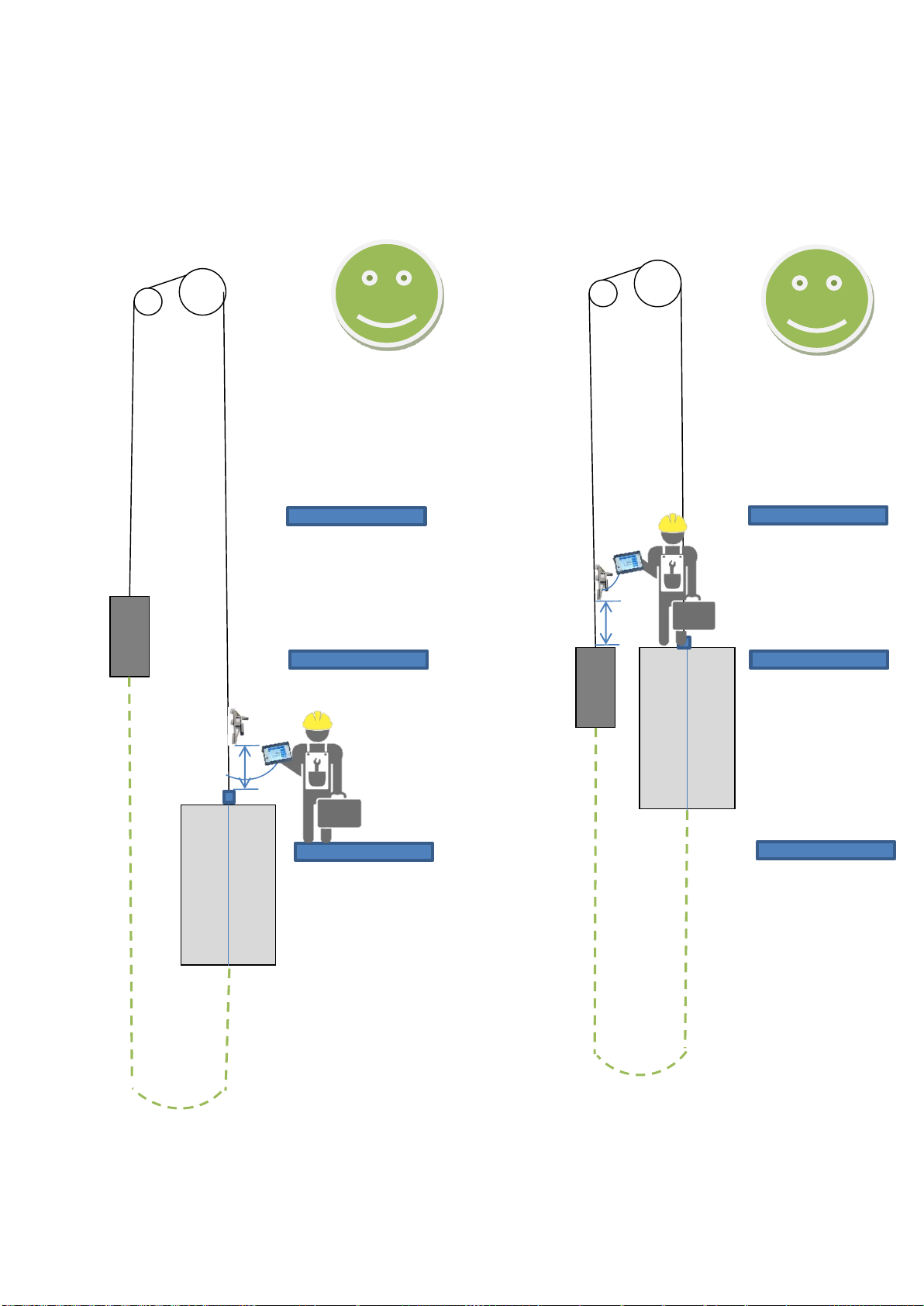
Lowest floor
floor
300
mm
compensation
chain
is not tightend!
CABIN
COUNTERWEIGHT
1:1 Suspension
Compensation chain
compensation
chain
is not tightend!
floor
floor
floor
floor
Page 32
Henning GmbH & Co. KG page 32 19/02/2019
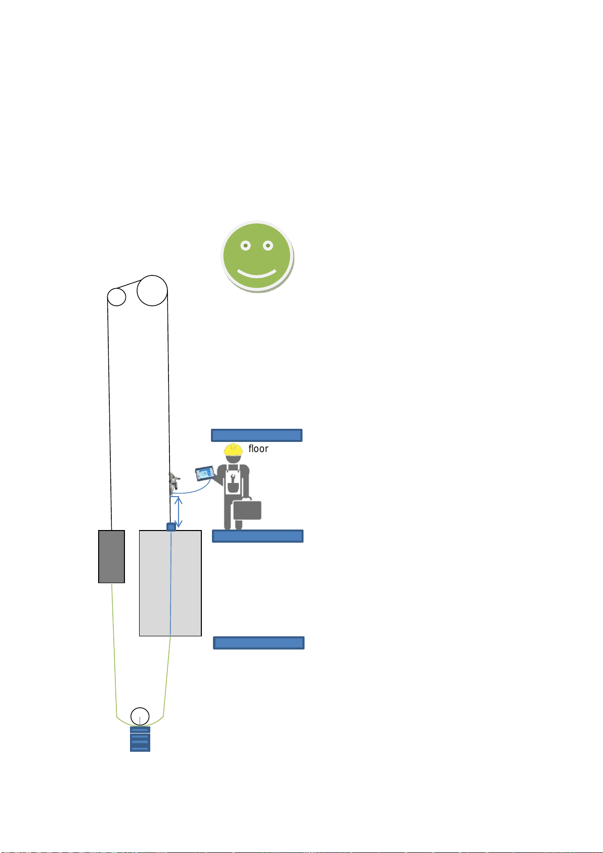
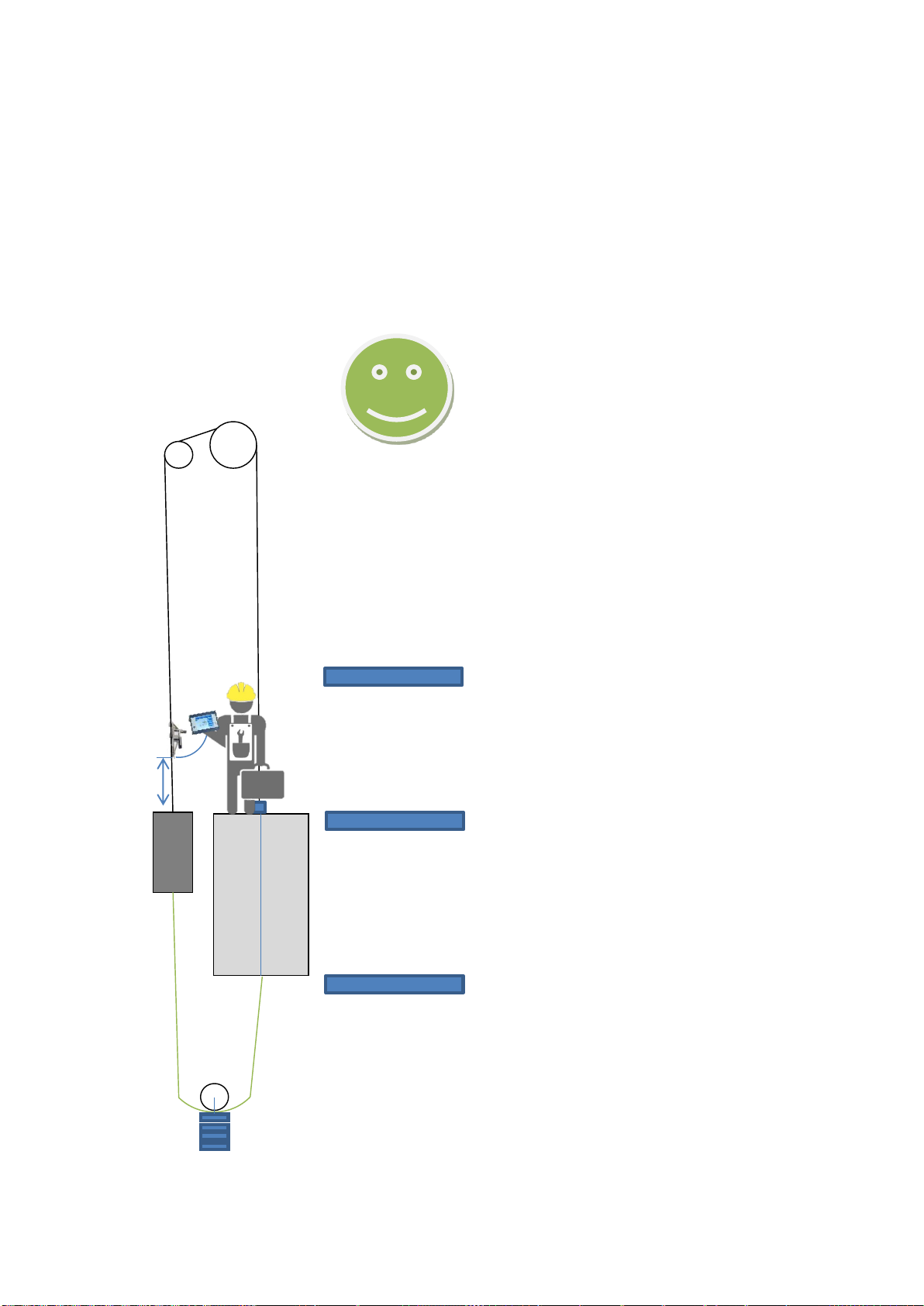
Step 1
1:1 Suspension with fixing weight
MEASUREMENT COMPENSATIONROPE / CABIN
300
mm
floor
floor
floor
Page 33
Henning GmbH & Co. KG page 33 19/02/2019
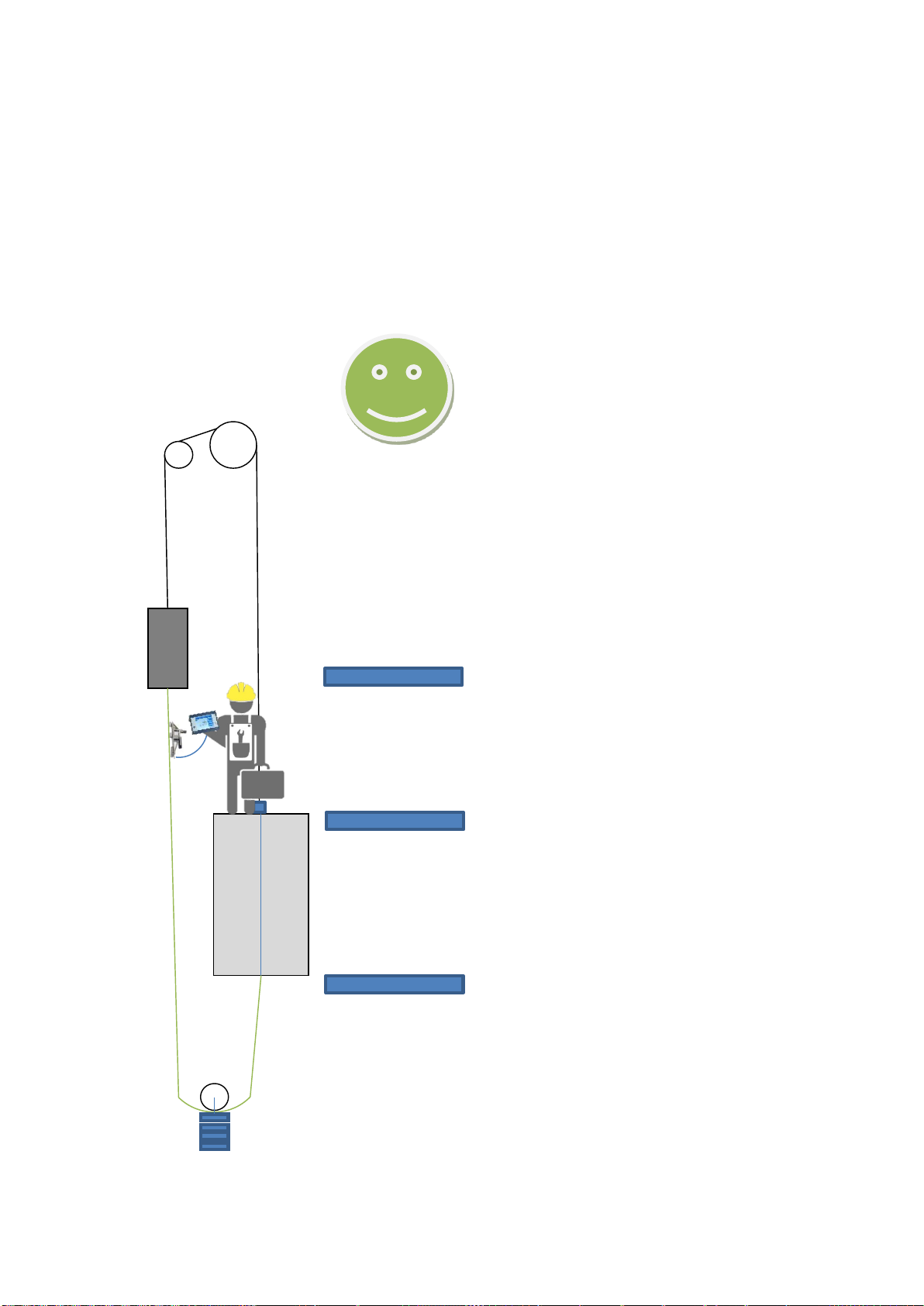
Step 2
1:1 Suspension with fixing weight
MEASUREMENT COMPENSATIONROPE/COUNTERWEIGHT
floor
floor
floor
300
mm
Page 34
Henning GmbH & Co. KG page 34 19/02/2019
Step 3
1:1 Suspension with fixing weight
MEASUREMENT COMPENSATIONROPE
floor
floor
floor
Page 35

Henning GmbH & Co. KG page 35 19/02/2019
7.A.3 Rope Adjustment
Generally, the sensors should be mounted in the section of the rope which features maximum lengths without intermediate deflections or traction sheaves, as the ropes will be balancing out only very slightly or none at all during standstill.
If this is not possible due to the layout of the elevator, several rope settings may be carried
out in succession. In between the adjustment procedures, the elevator should be driven
several times in order to compensate the ropes loads across the traction sheave.
7.A.4 Friction / Determination of Weight
Due to heavy friction of the car or the counterweight in the guide rails the measuring
result may be negatively affected. In such a case it is prefered to determine the weight
during a constant travel. This effect is found particularly often in the case of rucksack
guides. With roller guides this effect is found generally less frequently than with slide
type guides.
If possible, clamp the sensors onto the rope directly above the load to be measured (>= 200
mm) and subsequently travel a short distance upward with constant speed. If there is no
difference between the indicated load during the constant travel and while standing still,
there is no friction to speak of in the guides and it will not be necessary to carry out the
measurement during travel.
If there is a significant difference between the travel and the standstill value, make a note
of the value measured during the upward travel and then start a downward travel with constant speed. Make a note of this value too.
The average of the readings obtained during upward and downward travel is the real
weight without friction.
By this trick of traveling upwards and downwards and the subsequent determination of an
average value you have eliminated the dynamic and static friction of the elevator from the
measurements.
! Attention: In the case of multi-suspensions, please take extra special care that the
sensors are not overrun during the measuring travels!
Page 36
Henning GmbH & Co. KG page 36 19/02/2019
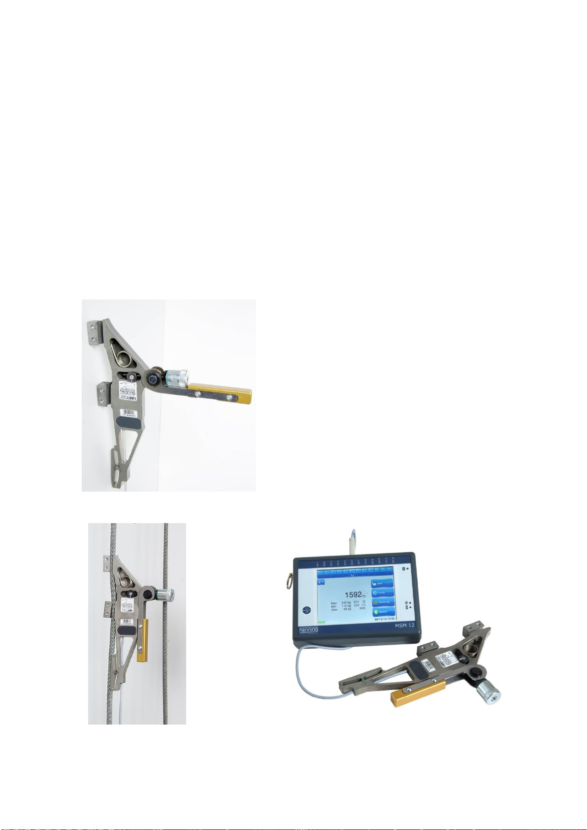
7.B Installation of Sensors LSM1 und LSM2
1. Bring the clamp lever into the “open” position. Place the sensor onto the
rope. If this is not possible, open the adjustment-screw several turns. When
the sensor is placed on the rope, turn the adjustment-screw in such a way,
that the marker matches the apropriate rope diameter on the label. This is
only a rough adjustment, the fine tuning will be done by the green o-ring on
the adjustment-screw.
2. Now close the clamp lever and taking care that the cable still runs correctly in the
sensor groove.
3. Connect the sensor LSM to the evaluation unit MSM12 via the USB cable.
Step 1
Step 2
Step 3
Page 37
Henning GmbH & Co. KG page 37 19/02/2019
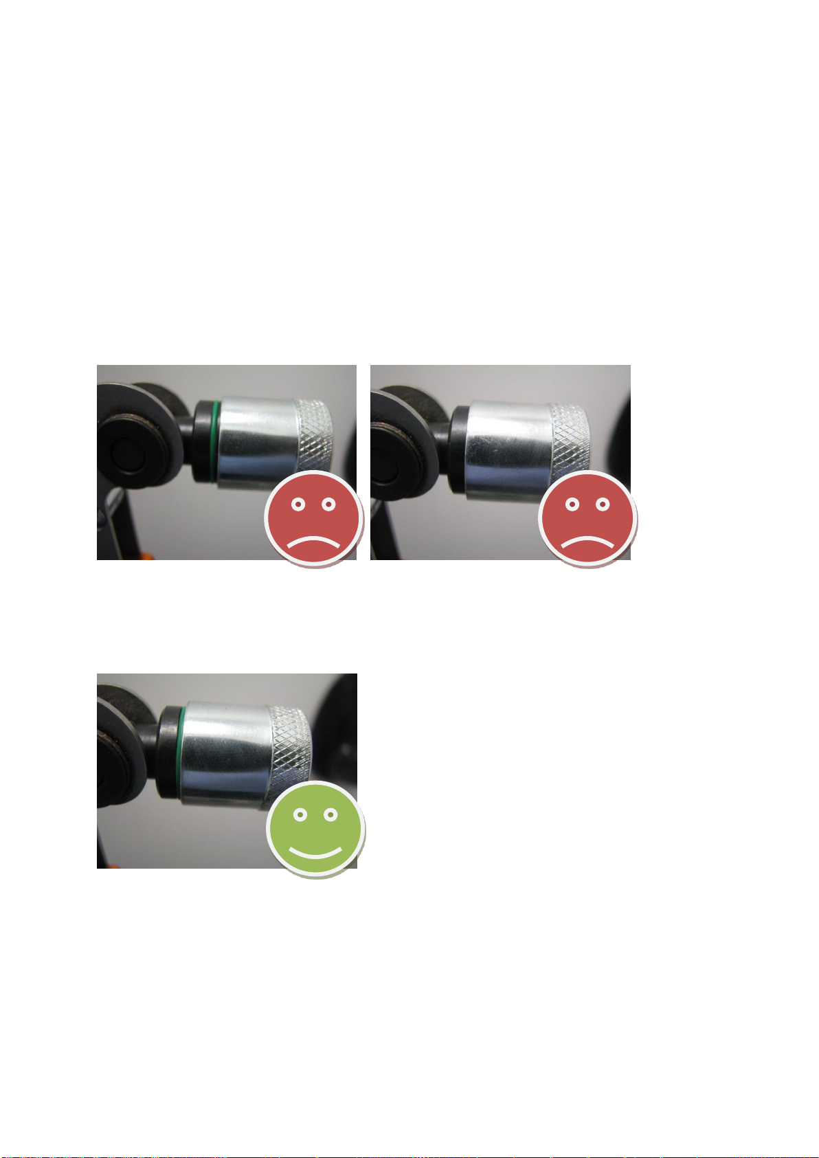
After installation, the correct sensor adjustment should be verified, to ensure that the sensor has been fitted with the right force. The clamping force is correct, if the edge of the adjustment screw’s silver cylinder is positioned in the center of the green o-ring. If the edge
of the silver cylinder is not positioned inside the O-ring, the clamping force is wrong and
the installation should be repeated.
The following pictures show correctly and incorrectly adjusted rope load sensors:
Incorrectly adjusted:
Correctly adjusted:
Page 38
Henning GmbH & Co. KG page 38 19/02/2019
7.C Installation of Sensors LSM-XL
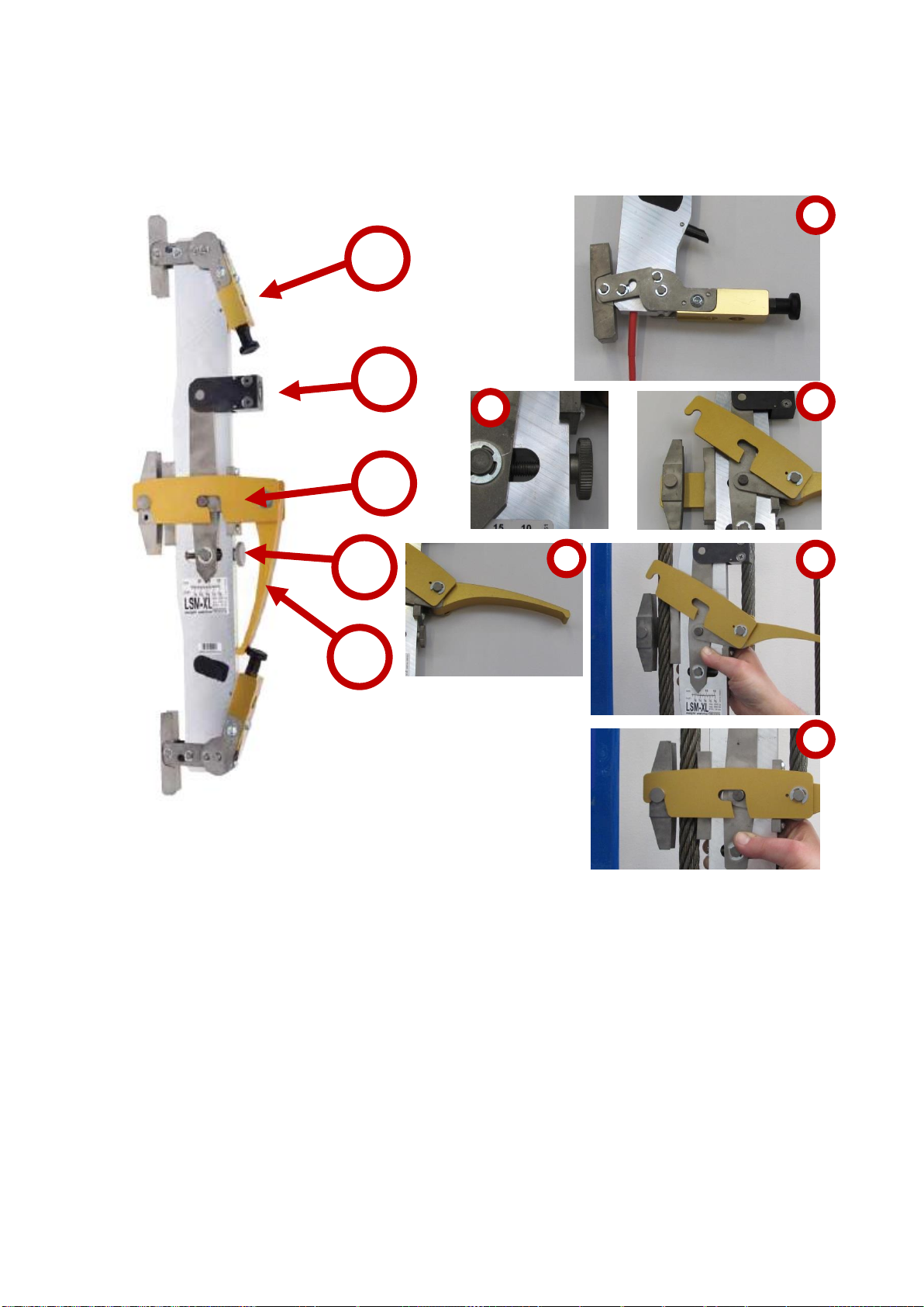
Open both levers 1 as well as lever 2, open strap 3. Adjust the sensor by means of the adjustment screw 4 roughly to the rope diameter and mount the sensor onto the rope. Close
strap 3 and after lever 2.
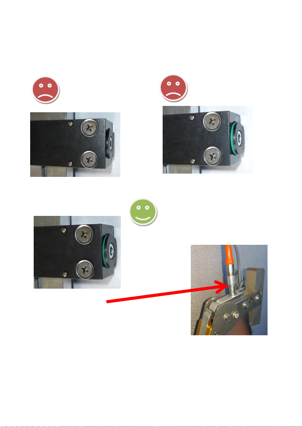
Check the clamping force on indicator 5. If the clamping force is correct, half of the green
O-ring will be visible. If this is not the case, open lever 2 again and adjust the clamping
force by means of the adjustment screw 4. Close lever 2 again and close both levers 1.
1
5
3
2
4
3
3
3
1
Page 39
Henning GmbH & Co. KG page 39 19/02/2019
The following pictures show correctly and incorrectly adjusted rope load sensors:
Incorrectly adjusted:
Correctly adjusted:
IMPORTANT ADVICE:
Take care when inserting or removing the cord
plugset.
Handle by the plug unit, never pull the electrical cord.
Align red dot on plug with red dot on receptacle of the
Sensor.
Forcing the plug in or out will damage pins and severely damage
sensor which will require unnecessary/costly repairs.
Page 40
Henning GmbH & Co. KG page 40 19/02/2019
7.D Installation of Sensors LSM-BELT
Place the sensor onto the belt and close the strap at the side. Make sure that the belt is
positioned correctly in the in the sensor’s corresponding groove. If the belt has only
grooves on one side, the flat side should be facing towards the sensor body.
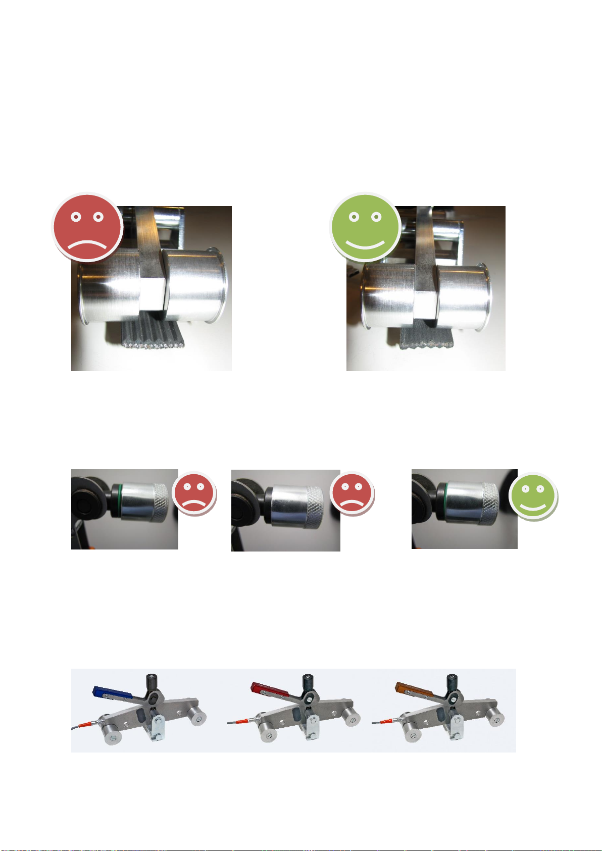
After installation, the correct sensor adjustment should be verified, to ensure that the sensor has been fitted with the right force. The clamping force is correct, if the edge of the
adjustment screw’s silver cylinder is positioned in the center of the green o-ring. If the edge
of the silver cylinder is not positioned inside the O-ring the sensor is incorrectly mounted.
Incorrectly adjusted: Correctly adjusted:
IMPORTANT:
DO NOT ADJUST SCREWS AS IT WILL VOID CALIBRATION OF SENSOR!
Belt versions:
OTIS SCHINDLER CONTITECH
Page 41

Henning GmbH & Co. KG page 41 19/02/2019
Henning GmbH & Co. KG
Loher Str. 4
58332 Schwelm
Deutschland
FON: 02336 / 9 29 8 – 0
FAX: 02336 / 9 29 8 – 100
eMail: [email protected]
URL : http://www.henning-gmbh.de
Service-Hotline: 02336 / 9 29 8 - 232
 Loading...