

Page 1
Henning
GmbH
&
Co. KG
Loher Str. 4
58332 Schwelm
Germany
fon: +49 2336 92 98-0
fax: +49 2336 92 98-100
[email protected]
www.henning-gmbh.de
www.henning-cnc.de
Operating Instructions for Elevator Buffers type LP
1 Scope of application
The Elevator Buffer type LP is an energy dissipation type buffer according to EN 81-1/2, EN 81-20, EN
81-50 5.5 and therefore can be universally used for all applications in the construction of elevators. The
EC type examination permits the use in passenger and freight elevators both under the elevator car and
under the counter weight.
2 Functional description
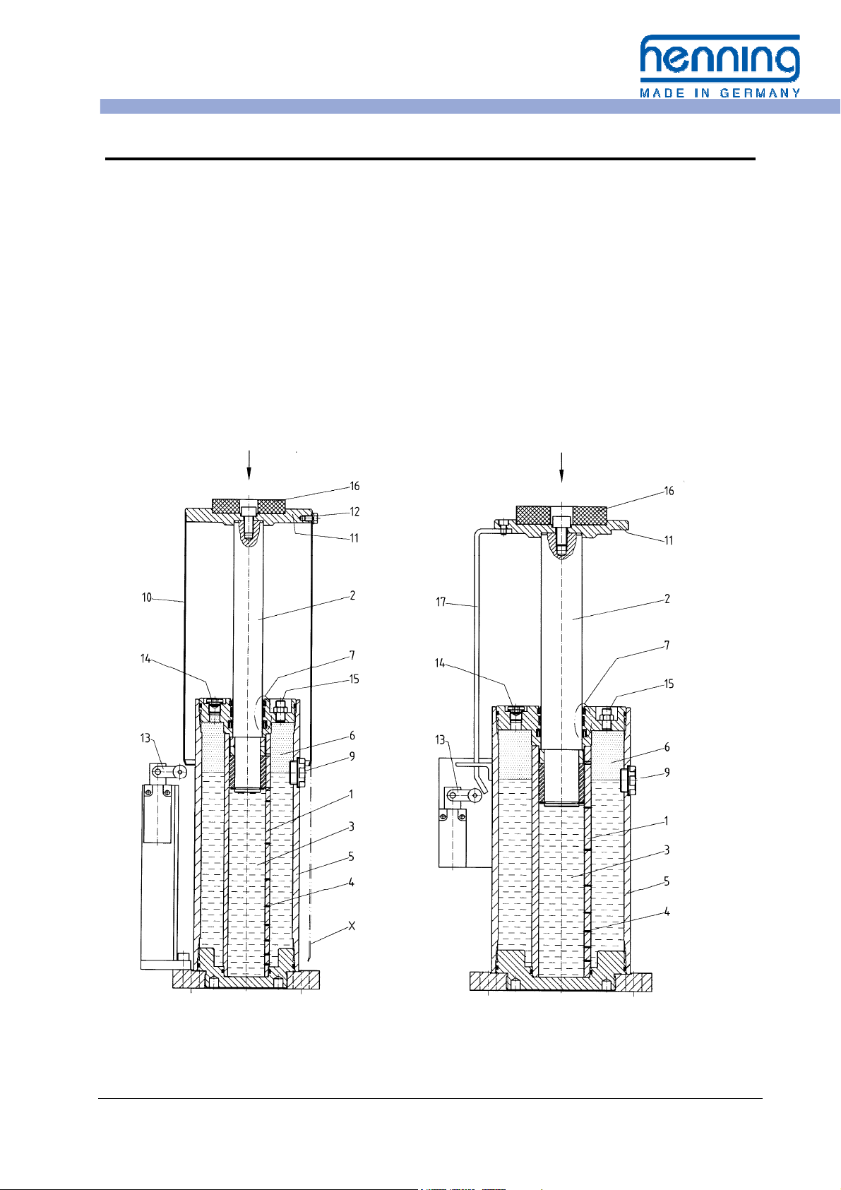
Fig. 1a: Buffer with Protection Tube Fig. 1b: Buffer with Linear Slide
Operating Instructions Elevator Buffers LP Page 1 Edition 3.3.1 EN of 03.04.2017
Page 2

Henning
GmbH
&
Co. KG
Loher Str. 4
58332 Schwelm
Germany
In the case of a buffer stroke the piston rod 2 is
forced into the cylinder tube 1 and the hydraulic
fluid 3 in the tube is displaced and forced to the
outside through small throttling ports 4 in the
tube wall. The fluid accumulates within the jacket tube 5.
At the same time the gas volume 6 above the
hydraulic medium is further compressed. The
sealing system 7 maintains a reliable seal between the hard chromium-plated piston rod and
the atmosphere.
After the buffer stroke and return to hydraulic
balance the compressed gas volume forces the
displaced fluid back into the cylinder and extends the piston rod.
The level of the hydraulic fluid at the gas interface can be read at any time through the sight
glass 9 without opening the unit.
fon: +49 2336 92 98-0
fax: +49 2336 92 98-100
[email protected]
www.henning-gmbh.de
www.henning-cnc.de
3 General Instructions
If people are working in the elevator shaft a
suitable refuge must be ensured.
Buffers are safety devices. Mounting, inspection and maintenance work
may only be carried out by expert personnel! Observe the
applicable safety instructions!
An elastic impact plate 16 damps the impact and
reduces the noise.
The limit switch 13 monitors the extended ready
position of the buffer. The limit switch is actuated
by pressure on the piston rod by the linear slide
17 or the protection tube 10 respectively.
In the case of buffers equipped with a protection
tube 10, for maintenance work the screws 12 on
the buffer head 11 are removed. Subsequently,
the protection tube can be lowered, which simultaneously actuates the switch 13. The oil filler
screw 14 and the gas-filling valve 15 will then be
accessible.
In the normal operating state the protection tube
avoids damage and contamination of the piston
rod.
For this purpose the general safety instructions
of the elevator manufacturer have to be observed.
Warning!
4 Preparations
4.1 Design Data
Among the data on the buffer type plate there is
included:
• Piston diameter and stroke
• Minimum impact mass,
• Maximum impact mass and
• Rated speed
4.2 Ambient Temperature Limit
The ambient temperature should be between
-10 °C and 50 °C.
The buffer can be supplied in a special design
filled with a special hydraulic oil for low ambient
Operating Instructions Elevator Buffers LP Page 2 Edition 3.3.1 EN of 03.04.2017
The first check should be to ensure that the operating conditions do not exceed this design
data.
temperatures. This buffer can be used between
-20 °C and +40 °C and is labelled with a special
designation for this temperature range. An enhanced EC type examination is also provided.
Page 3

Henning
GmbH
&
Co. KG
Loher Str. 4
58332 Schwelm
Germany
4.3 Place of Installation
The place of installation should be in a clean
and dry condition.
Verify the place of installation of the buffer and
the bearing capacity of the mounting surface.
Verify the size of the remaining lower refuge. For
an entirely pressed-in elevator car buffer a sufficiently dimensioned refuge must be provided
below the elevator car in compliance with the
respective code.
fon: +49 2336 92 98-0
fax: +49 2336 92 98-100
[email protected]
www.henning-gmbh.de
www.henning-cnc.de
5 Mounting
The piston rod should not be contaminated by
external impact.
During operation of the elevator it has to be ensured that the surface of the piston rod is free of
adherences of snow and/ or ice and not frosted.
In case of dissenting operation conditions,
please contact Henning GmbH & Co KG.
Safety Instruction:
Prior to all mounting and maintenance work, an appropriate measure to prevent au-
!
1. The buffer is supplied ready for installation
complete with oil filling.
2. If the buffer is supplied with pressed-in piston rod, the securing devices should be removed. Cut the securing straps at the side
when the buffer is standing upright.
Warning! The extending piston rod can
cause injury!
3. Fastening material should be ordered separately. Suitable means are heavy-duty dowels or rag bolts M 16x160 DIN 529 with nuts
and washers 18 DIN 126.
4. Fastening should be made in the upright
condition directly on the ground or on a suit-
tomatic switching on or automatic start-up of the drive must be in place!
able console. The buffer piston rod should
be accurately mounted in the vertical position. Therefore, mounting must be made on
a horizontal surface or suitable shims should
be used.
5. The buffer should be fixed exactly under the
centre of gravity of the elevator car or counterweight respectively. If several buffers are
used, these must be distributed symmetrically to the centre. Check the alignment of
the buffer e. g. using a water level. The piston rod has to point vertical up.
6. Press-in the piston rod several times by
hand. This permits transport-caused air
bubbles to escape from the hydraulic fluid.
Subsequently, the piston rod must be completely extended and the oil level correct.
If buffers may be displaced for service work
at the elevator e. g. by
• swinging to a service position
• removing
please note:
Operating Instructions Elevator Buffers LP Page 3 Edition 3.3.1 EN of 03.04.2017
or
1. The elevator may only be set into operation again if the buffer
is replaced to its working position and fastened correctly. We
recommend installing a suitable electrical controlling device.
2. Then press-in the piston rod of the buffer at least two times.
This allows air bubbles escaping from the hydraulic cylinder.
3. Finally check, that the piston rod is fully extended and the oil
level is correct.
4. Fix suitable instructions for acting near the point of installation.
Page 4

Henning
GmbH
&
Co. KG
Loher Str. 4
58332 Schwelm
Germany
5.1 Electric Connection
During connection work the installation must be de-energised!
fon: +49 2336 92 98-0
fax: +49 2336 92 98-100
[email protected]
www.henning-gmbh.de
www.henning-cnc.de
Dangerous Voltage!
Carry out the electric connection to the limit
switch 13 (Figures 1a or 1b). During wiring the
working range of the linear slide 17 and the
6 Commissioning
Safety Instruction:
During buffer testing no persons are allowed
!
1. Verify the extended position of the piston
rod and the oil level.
2. Carry out a first buffer test with reduced
speed and without additional load.
3. Verify the electrical signal of limit switch 13.
4. Wait for approx. 1 - 2 minutes and then re-
lieve the buffer.
5. Verify the extended position of the piston
rod and the oil level. Check the buffer and
to stay in the elevator shaft!
protection tube 10 during buffer stroke must be
observed.
the impact point for possible damage and oil
leaks.
6. If no defects are found, carry out a second
buffer test. This test should be carried out, if
possible, with rated speed and maximum
load.
7. Repeat points 4. and 5. .
If no defects are found, the buffer is ready for
operation.
7 Regular inspections
During regular inspections of the elevator installation or for trouble shooting the following
7.1 Inspection of the extended piston rod
Buffer with protection tube to Fig. 1a:
• The sight glass 9 is not masked by the pro-
tection tube 10.
• The limit switch 13 is not actuated.
Operating Instructions Elevator Buffers LP Page 4 Edition 3.3.1 EN of 03.04.2017
inspections are possible for which all the a/m
safety instructions must be observed:
Buffer with linear slide to Fig. 1b:
• The limit switch 13 is not actuated.
• The visible part of the piston rod is as long
as the respective stroke (see indication on
the type plate).
Page 5
Henning
GmbH
&
Co. KG
Loher Str. 4
58332 Schwelm
Germany
fon: +49 2336 92 98-0
fax: +49 2336 92 98-100
[email protected]
www.henning-gmbh.de
www.henning-cnc.de
7.2 Oil level check
The elevator buffers series LP are equipped
with a sight glass as an oil indicator. Therefore,
the buffer does not need to be opened for the oil
level check! This inspection should only be carried out with fully extended piston rod (see a/m
point 7.1).
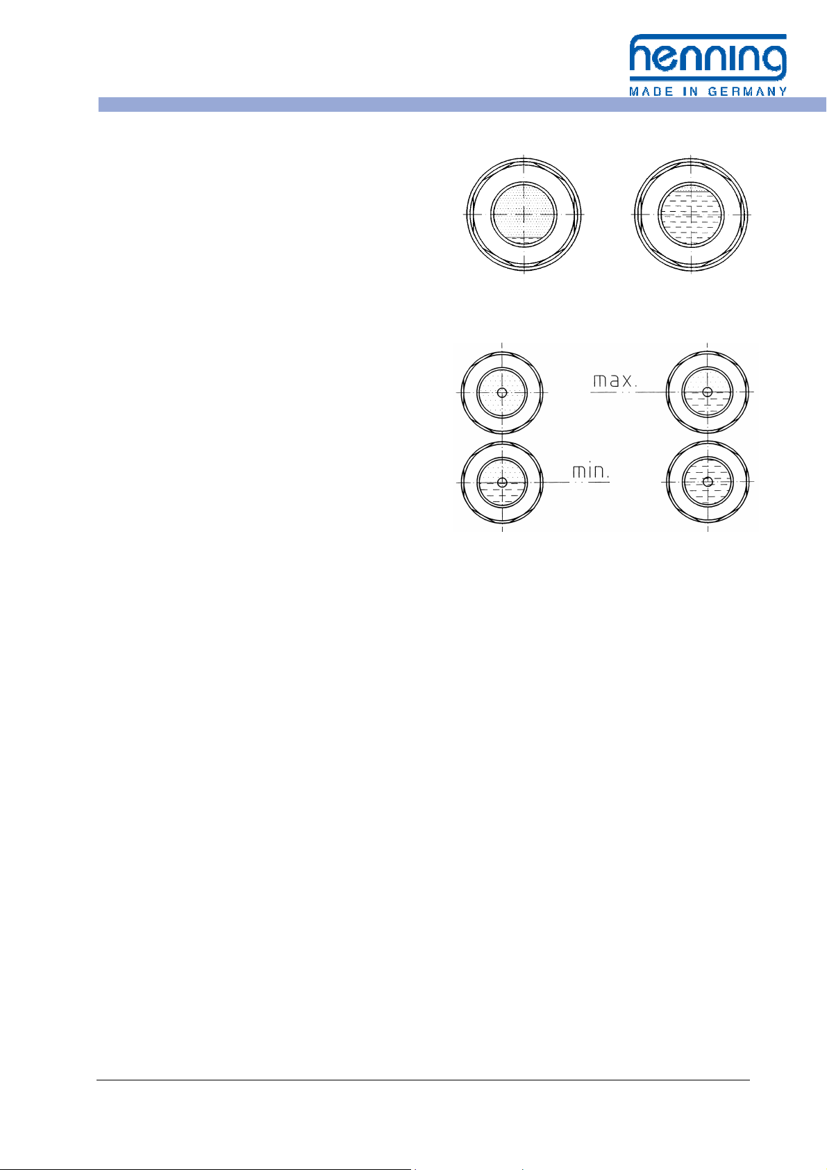
a) Buffer with one sight glass
The oil level should be visible in the
sight glass 9, see Fig. 2a
b) Buffer with two sight glasses
- minimum: the oil level is visible in
the lower sight glass
- maximum: the oil level is below the
top edge of the upper
sight glass
see Fig. 2b
Factory oil filling for buffers with one sight glass
is up to the centre of the sight glass (at ambient
temperatures of 16 °C to 22 °C).
Factory oil filling for buffers with two sight glasses is below the top edge of the upper sight
glass.
The oil level is depending on temperature. At
ambient temperatures around freezing point, the
oil level can drop near the minimum. High ambient temperatures let the oil level rise.
If during the oil level check the oil level is found
to be too high, air bubbles might be in the oil. In
this case first press the piston rod of the (upright
7.3 Gas pressure check
For resetting the piston rod after a buffer stroke
the buffer is filled with nitrogen. The gas pressure at extended piston rod is 5 bar.
The gas pressure may be checked without using
a measuring instrument. For this purpose press
7.4 General visual inspection
Pay attention to oil spots on the floor or on the
buffer. An oil film on the piston rod 2 is normal.
Check the piston rod surface for damage and
tightly adherent contaminations.
Oil level minimum Oil level maximum
Fig. 2a: Oil level indication with one sight glass
Oil level minimum Oil level maximum
Fig. 2b: Oil level indication with two sight glasses
standing) buffer several times as far as possible.
If the oil level is not falling although the piston
rod is fully extended, oil must be removed.
If the oil level is too low, oil must be added (see
point 8.3 "Correction of the oil level"). In this
case check the buffer for leakage.
the piston rod by hand for some centimetres.
If the piston rod then returns automatically to its
initial position, the gas pressure is sufficient.
Otherwise proceed as described under point 8.4
"Gas refilling".
Check the state and function of the limit
switch 13.
If leaks or damage is found, the buffer must be
exchanged or repaired.
Operating Instructions Elevator Buffers LP Page 5 Edition 3.3.1 EN of 03.04.2017
Page 6

Henning
GmbH
&
Co. KG
Loher Str. 4
58332 Schwelm
Germany
7.5 Check the piston rod for icing
If the buffer is operated at ambient temperatures
below the freezing point, the piston rod must be
protected from the accumulation of frost, snow
fon: +49 2336 92 98-0
fax: +49 2336 92 98-100
[email protected]
www.henning-gmbh.de
www.henning-cnc.de
8 Maintenance
Under normal operating conditions the elevator
buffer LP does not require maintenance. However, if during the a/m checks defects are detected, these can be removed as described in
the following.
8.1 Removing the protection tube
For buffers with a protection tube (Fig. 1a) this
should be removed for maintenance work. For
this purpose remove the three hexagonal screws
12. Push the protection tube 10 downward into
the service position "X". The oil filling screw 14
or ice. It is necessary to check whether the
measures taken to prevent icing are functioning
properly.
Every time, safety measures must be taken
against unintentional setting in motion of the
elevator!
and the gas filling valve 15 are now accessible.
At the same time the limit switch 13 is actuated.
After termination of the maintenance work the
protection tube is mounted in reverse order.
The buffer is pressurised.
!
8.2 Relieving gas pressure
Remove the valve cap from the gas filling valve
15 in order to uncover the valve opening.
Place a tire filling device on the filling valve and
let the gas escape. As an alternative you can
Prior to opening the buffer and for oil refilling the pressure must be released!
Warning!
press in the valve cone with a suitable pointed
object and let the gas escape.
.
Operating Instructions Elevator Buffers LP Page 6 Edition 3.3.1 EN of 03.04.2017
Page 7

Henning
GmbH
&
Co. KG
Loher Str. 4
58332 Schwelm
Germany
fon: +49 2336 92 98-0
fax: +49 2336 92 98-100
[email protected]
www.henning-gmbh.de
www.henning-cnc.de
8. 3 Correction of the oil level
• Remove the oil filling screw 14 after hav-
ing relieved the gas pressure.
• For refilling use the following oil types
only:
a) buffer standard model (-10 °C up to
+50 °C):
Hydraulic oil DIN 51524-2 HLP respectively ISO 6743/4 HM viscosity ISO
VG 46
b) buffer with low temperature design
(-20 °C up to +40 °C, see label):
Hydraulic oil DIN 51524-3 HVLP respectively ISO 6743/4 HV viscosity ISO VG
22
• Refill the hydraulic oil:
- buffers with one sight glass: until the
oil level is in the centre of the sight
glass
- buffers with two sight glasses: until the
oil level is below the top edge of the
upper sight glass
8.4 Gas refilling
• Remove the cap from the gas filling
valve 15.
• Place a tire filling device on the filling
valve. All commercially available filling
systems can be used for car tire valves
VG8.
• Fill the buffer with nitrogen gas, filling
pressure 5 bar. The filling pressure must
not be exceeded.
• The piston rod should now be fully ex-
tended.
• If the oil level is too high (see 7.2), oil
must be removed.
• The limit values of the oil levels (see Fig.
2a/2b) should absolutely be observed.
The correct oil level is only indicated if
the piston rod is fully extended. In the
case of too high an oil level there is a
danger that the buffer becomes overloaded during buffer stroke. If the oil
level is too low, the damping effect of
the buffer may be reduced.
• Then replace the oil filling screw 14.
Make sure a new copper sealing ring A
14x18 DIN 7603 is used.
• Subsequently refill gas.
If an inspection book is kept for the elevator
buffer, the oil level corrections should be recorded here.
• The use of pressurized air instead of ni-
trogen is allowed. Never fill with oxygen
or other inflammable gases such as
propane and acetylene!
• Finally check the gas filling valve 15 and
the oil filling screw 14 with a leakdetecting spray or soap water for gas
tightness.
• Replace the valve cap.
Operating Instructions Elevator Buffers LP Page 7 Edition 3.3.1 EN of 03.04.2017
Page 8

Henning
GmbH
&
Co. KG
Loher Str. 4
58332 Schwelm
Germany
fon: +49 2336 92 98-0
fax: +49 2336 92 98-100
[email protected]
www.henning-gmbh.de
www.henning-cnc.de
9 Measures during operation
9.1 What is to be done after a buffer stroke?
During normal elevator operation the buffers do
not come into operation. Therefore, a buffer
stroke is regularly the result of an operation failure.
9.2 What is to be done if oil leakage is detected?
Search for the location of oil leak. If leaking oil is
visible and the leak cannot be stopped, the buffer should be changed immediately.
In the case of small leaks the buffer may remain
in use. At first check the oil level of the buffer. If
the oil level is below the minimum (Fig. 2a/2b),
refill oil (see chapter 8). Subsequently, the buffer
should be checked at shorter intervals.
9.3 What is to be done in the case of too low an oil level?
Check the buffer for leakages. If no leaks are
found, oil should be refilled (see chapter 8).
9.4 What is to be done in the case of too high an oil level?
Too high an oil level can only occur if too large a
quantity of oil has been refilled. Follow the instructions under point 7.2 "Oil level check".
9.5 What to do if the piston rod will no longer fully extend?
Refill nitrogen as described under point 8.4.
Check the entire buffer with leak detecting spray
or soap water for possible gas leakage. If the
9.6 What is to be done if the piston rod is damaged?
Damaged or bent piston rods impair the functional safety of the buffer. Such buffers should
After release of the buffer and the signalling of
the piston rod reset (limit switch 13), as a rule,
the elevator is again ready for operation.
Nevertheless, we recommend a full visual inspection of the buffer and the elevator.
In the case of any doubt regarding the state of
the buffer, it should be changed. For this purpose Henning offers a repair/exchange service
for buffers.
Leaked oil should be absorbed using oil binder
or cleaning rags.
If oil is leaking, proceed as described in chapter
9.2.
Make sure that the piston rod is entirely extended. If oil must be removed, follow chapter 8.
problem still exists, the buffer should be exchanged or repaired by skilled personnel.
be exchanged or repaired by skilled personnel.
Operating Instructions Elevator Buffers LP Page 8 Edition 3.3.1 EN of 03.04.2017
Page 9

Henning
GmbH
&
Co. KG
Loher Str. 4
58332 Schwelm
Germany
fon: +49 2336 92 98-0
fax: +49 2336 92 98-100
[email protected]
www.henning-gmbh.de
www.henning-cnc.de
10 Service
For ordering replacement parts, please, contact
our Service Department.
Henning GmbH & Co KG offers elevator buffers
as repair/ exchange. These buffers can be supplied in a short time, have been overhauled in
our works and are supplied with full manufacturer's guaranty.
11 Recycling
At the end of its working life, the buffer can be
recycled as follows:
• Relieve the gas pressure as described
in 8.2
The following buffer-specific data is always required:
• Buffer type
• Serial number
• Maximum and minimum impact mass
• Rated travel speed.
• Fully remove the hydraulic oil and sup-
ply it to company for used oil recycling
• Dispose of the buffer as iron scrap
Operating Instructions Elevator Buffers LP Page 9 Edition 3.3.1 EN of 03.04.2017
Page 10
Henning
GmbH
&
Co. KG
Loher Str. 4
58332 Schwelm
Germany
fon: +49 2336 92 98-0
fax: +49 2336 92 98-100
[email protected]
www.henning-gmbh.de
www.henning-cnc.de
Appendix
Technical Data:
Size x Stroke
s [mm]
LP 40 x 80 1,0 450 - 3200 4,96 90 14
LP 40 x 120 1,3 450 - 3200 7,44 90 16
LP 40 x 175 1,6 450 - 3200 10,9 90 19
LP 40 x 275 2,0 450 - 3200 17,1 90 24
LP 40 x 430 2,5 450 - 3200 26,7 90 32
LP 50 x 425 2,5 500 - 4500 37,4 130 47
Rated speed
max.
v [m/s]
Impact mass
min. - max.
m [kg]
Impact energy
max.
E [kNm]
Buffer force
max.
F [kN]
Weight with oil
filling
G [kg]
LP 50 x 695 3,2 500 - 4500 61,1 130 68
LP 50 x 950 3,7 500 - 4500 83,5 130 86
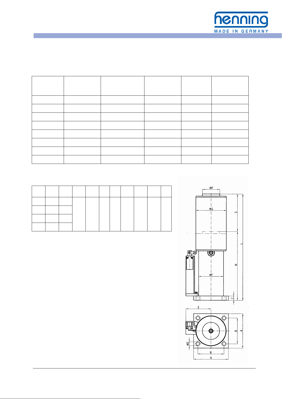
Dimensions Type LP 40 with protection tube:
S L N A B C D E F G P
80 305 225
120 385 265
175 495 320
275 715 440
All dimensions in mm.
All data subject to modifications!
160 120 20 18 112 115 140 80
Operating Instructions Elevator Buffers LP Page 10 Edition 3.3.1 EN of 03.04.2017
Page 11
Henning
GmbH
&
Co. KG
Loher Str. 4
58332 Schwelm
Germany
fon: +49 2336 92 98-0
fax: +49 2336 92 98-100
[email protected]
www.henning-gmbh.de
www.henning-cnc.de
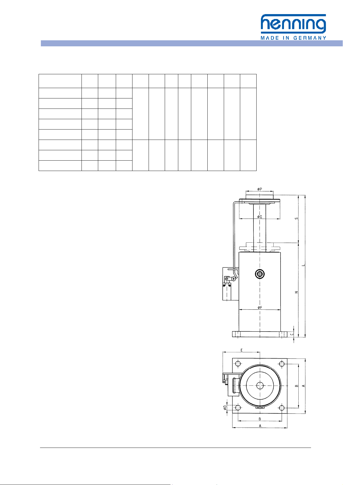
Dimensions Type LP 40 / 50 with linear slide:
S L N A B C D E F G P
LP 40 x 80 80 305 225
LP 40 x 120 120 385 265
LP 40 x 175 175 495 320
160 120 20 18 116 115 130 80
LP 40 x 275 275 715 440
LP 40 x 430 430 1065 635
LP 50 x 425 425 1065 640
200 160 20 18 135 155 150 100 LP 50 x 695 695 1665 970
LP 50 x 950 950 2235 1285
All dimensions in mm.
All data subject to modifications!
Hydraulic oils and allowed ambient temperatures
during elevator operation:
a) buffer standard model:
Hydraulic oil DIN 51524-2 HLP respective ISO 6743/4 HM
viscosity ISO VG 46 for ambient temperatures from
-10 °C up to +50 °C
b) buffer with low temperature design (upon request):
Hydraulic oil DIN 51524-3 HVLP respective ISO 6743/4 HV
viscosity ISO VG 22 for ambient temperatures from
-20 °C up to +40 °C
c) Special designs with biodegradable or flame-retardant
hydraulic fluids (on request):
Various special fluids are tested for the hydraulic buffer LP and
released for use.
Please note the special marking of the buffer and the additional
inserts for order documentation in the individual case!
Operating Instructions Elevator Buffers LP Page 11 Edition 3.3.1 EN of 03.04.2017
 Loading...