

Page 1
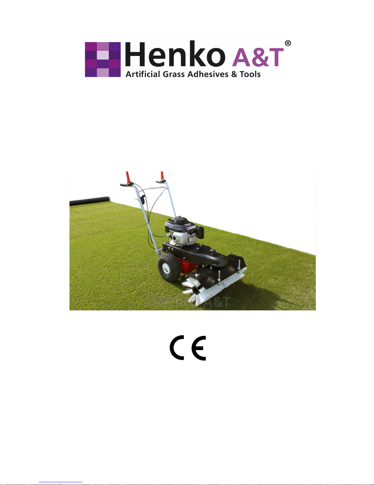
Operating Manual
Henko 671 Brush Machine
Henko A&T B.V.
Graafschap Hornelaan 184, 6004 HT Weert,
The Netherlands
Tel: +31 (0)495 63 30 10, Fax: +31 (0)495 58 67 35
[email protected], www.henko-at.nl
© Henko A&T B.V.
Rev. 18-8-2014
Page 2

Page 2 of 33
18-8-2014
Henko A&T B.V.
Introduction
Dear reader,
This operating manual provides all information for
safe operation of the Henko 671 Brush Machine.
The Henko 671 Brush Machine has been designed and built in
accordance with the state of the art and recognised safety rules
and regulations. Nevertheless dangers for personnel or objects
can occur, because not all danger zones can be avoided if the
functionality is to remain intact. However you can prevent
accidents due to these dangers by complying with the
instructions in this operating manual. Moreover you will then be
able to use the Brush Machine to its full capacity and avoid
unnecessary disturbances.
CAUTION!
There is danger of injury and danger of material damage
when assembling, operating, and maintaining the Brush
Machine. Therefore:
First read this operating manual carefully, prior to assembly
and operation of the Brush Machine. Always comply with the
instructions and information contained herein, particularly the
safety instructions.
If the operating manual is lost or in poor condition, request a
new copy from the manufacturer (the same applies for parts of
the operating manual).
This operating manual only applies for the Brush Machine
specified on the cover sheet and at the end of every page.
Compare this information with the information on the type plate
of the Brush Machine.
After you have read the entire operating manual thoroughly for
the first time, take good care of the operating manual over the
entire service life of the Brush Machine, so that you can look up
something later.
If you sell the Brush Machine, give this operating manual to
the new owner.
All information, illustrations and dimensions in this operating
manual are non-binding. No claims whatsoever can be derived
from this information, illustrations or dimensions.
Introduction
Page 3

Henko A&T B.V. 18-8-2014 Page 3 of 33
Reprinting or duplication of any type, including excerpts,
requires the written permission of the manufacturer.
Conversion of, or changes to the Brush Machine are only
permitted with the manufacturer's written consent.
Unauthorised conversion voids any liability on the part of the
manufacturer, as well as the guarantee.
Only use original spare parts and accessories that are
approved by the manufacturer. Otherwise the design-specified
characteristics of the Brush Machine, the functionality or the
safety can be impaired. Consequently the use of other parts
voids the liability for the ensuing consequences.
Contact your specialist dealer to order spare parts or
accessories.
In addition comply with the instructions in the operating manual
of the motor manufacturer. This is included in the sub-package
for the Brush Machine.
Henko A&T B.V. assumes no liability for the content of the
operating manual provided by the motor manufacturer.
Explanation of symbols, signs and direction indications
For better understanding, the following conventions are used for
this operating manual:
1.
To emphasise important information, the following types of
special notices are used:
DANGER!
There is an imminent dangerous situation that results in death
or serious injury if it is not avoided.
WARNING!
There is a possible dangerous situation that can result in death
or serious injury if it is not avoided.
Introduction
Page 4

Page 4 of 33
18-8-2014
Henko A&T B.V.
CAUTION!
There is a possible dangerous situation that can result in
minor injury or material damage, if it is not avoided.
ATTENTION!
...indicates a possible dangerous situation that can result in
material damage, if it is not avoided.
NOTE
...indicates useful tips and recommendations, as well as
information for efficient and trouble-free operation.
...refers to important information in other sections and documents.
2.
Many texts serve a particular purpose. These texts are marked
as follows:
Listings.
Instructing text, e. g. a sequence of activities.
3.
In the text the sides of the Brush Machine are cited (left, right,
front, rear). Left or right refers to the side that the operator of
the machine sees viewed from the direction of travel. The Brush
Machine of the machine is mounted in front, the steering arm is
mounted in the rear.
Introduction
Page 5

Henko A&T B.V. 18-8-2014 Page 5 of 33
Table of contents
Introduction . . . . . . . . . . . . . . . . .. . . . . . . . . . . . . . . . . . . . . 2
Table of contents . . . . . . . . . . . . . . . . . . . . . . . . . . . . . . . . . . 5
1 Safety . . . . . . . . . . . . . . . . . . . . . . . . . . . . . . . . . . . . . . . . . . 7
1.1 Intended use . . . . . . . . . . . . . . . . . . . . . . . . . . . . . . . . 7
1.2 Non-intended use . . . . . . . . . . . . . . . . . . . . . . . . . . . . 8
1.3 Product observation . . . . . . . . . . . . . . . . . . . . . . . . . . 8
1.4 Requirement imposed on the operator or personnel . 9
1.5 Danger zone . . . . . . . . . . . . . . . . . . . . . . . . . . . . . . . . 9
1.6 Work clothing . . . . . . . . . . . . . . . . . . . . . . . . . . . . . . . 11
1.7 Safety devices and protective devices . . . . . . . . . . . 11
1.7.1 Safety switch . . . . . . . . . . . . . . . . . . . . . . . . . 11
1.7.2 Brush Machine deck . . . . . . . . . . . . . . . . . . 11
1.7.3 Protective cover . . . . . . . . . . . . . . . . . . . . . . . 11
1.8 Safety regulations and accident
prevention regulations . . . . . . . . . . . . . . . . . . . . . . . 12
1.9 Disposal . . . . . . . . . . . . . . . . . . . . . . . . . . . . . . . . . 13
1.10 Safety signs on the Brush Machine . . . . . . . . . 14
2 Description . . . . . . . . . . . . . . . . . . . . . . . . . . . . . . . . . . . . 15
2.1 Overview . . . . . . . . . . . . . . . . . . . . . . . . . . . . . . . . . 16
2.2 Technical data . . . . . . . . . . . . . . . . . . . . . . . . . . . . . 17
3 Commissioning . . . . . . . . . . . . . . . . . . . . . . . . . . . . . . . . 18
3.1 Unpacking . . . . . . . . . . . . . . . . . . . . . . . . . . . . . . . . 18
3.2 Making the steering arm operational . . . . . . . . . . . . 19
4 Operation . . . . . . . . . . . . . . . . . . . . . . . . . . . . . . . . . . . . . 21
4.1 Preparatory activities . . . . . . . . . . . . . . . . . . . . . . . . 23
4.1.1 Adjusting the height of the Brush Machine . . 24
4.1.2 Checking the motor oil level . . . . . . . . . . . . . . 24
4.1.3 Filling fuel . . . . . . . . . . . . . . . . . . . . . . . . . . . . 25
Table of contents
Page 6

Page 6 of 33
18-8-2014
Henko A&T B.V.
4.2 Sweep operation . . . . . . . . . . . . . . . . . . . . . . . . . . . 25
4.2.1 Starting the motor . . . . . . . . . . . . . . . . . . . . . . 25
4.2.2 Stopping the motor . . . . . . . . . . . . . . . . . . . . . 26
4.2.3 Switching the traction drive on and off . . . . . . 26
4.2.4 Switching the Brush Machine drive
on and off . . . . . . . . . . . . . . . . . . . . . . . . . . . . 26
4.2.5 Side adjustment of the Brush Machine . . . . . 27
5 Maintenance and repair . . . . . . . . . . . . . . . . . . . . . . . . . . 28
5.1 Safety guidelines for maintenance and repair . . . . . 28
5.2 Regular maintenance tasks . . . . . . . . . . . . . . . . . . . 29
5.2.1 Maintenance schedule . . . . . . . . . . . . . . . . . . 29
5.2.2 Maintenance records . . . . . . . . . . . . . . . . . . . . 30
5.2.3 Checking the Bowden cables
for ease of movement . . . . . . . . . . . . . . . . . . . 30
5.2.4 Checking the air pressure in the tyres . . . . . . . 31
5.2.5 Cleaning the Brush Machine . . . . . . . . . . 31
5.2.6 Checking and cleaning the air filter . . . . . . . . . 31
5.3 Maintenance and repair verifications . . . . . . . . . . . . 32
6 Decommissioning and preservation . . . . . . . . . . . . . . . 33
7 Faults and fault correction . . . . . . . . . . . . . . . . . . . . . . . . 33
Table of contents
Page 7

Henko A&T B.V. 18-8-2014 Page 7 of 33
1 Safety
The basic prerequisite for safe and trouble-free operation of the
Brush Machine is knowledge of the safety instructions and
safety regulations.
Consequently read this chapter carefully all the way through
and comply with the specified instructions and warnings.
The safety instructions and warnings that you find at the
appropriate point in the text of the following chapters must be
complied with. The manufacturer cannot be made liable if the
instructions and warnings are not complied with.
In addition to the instructions contained in this operating
manual, the statutory regulations, particularly the safety and
accident prevention regulations, must also be complied with.
1.1 Intended use
The Henko 671 Brush Machine may only be used to brush
artificial grass, clean paths and surfaces that are paved with
concrete, asphalt, paving stones or slabs outside of closed
rooms.
Intended use also includes compliance with all the instructions
in the operating manual.
DANGER!
If the Brush Machine is used for a use other than the use
described above, dangerous situations can occur for people or
material damage can occur.
Therefore:
Only use the Brush Machine for its intended purpose.
Always comply with all the instructions in this operating
manual.
Particularly refrain from the uses of the sweeping machine
listed in section 1.2. They are considered non-intended use.
Safety
Page 8

Page 8 of 33
18-8-2014
Henko A&T B.V.
1.2 Non-intended use
Any use that deviates from that described in section 1.1, is
considered non-intended use.
For example, non-intended use of the Brush Machine
occurs when
it is used to clean unpaved surfaces e.g. gravel paths,
it is used to clean roofs or flat roofs,
it is used in enclosed spaces, e.g. halls, or barns,
it is used to transport persons or objects,
it is used to move or carry objects or vehicles,
it is operated in faulty condition or with safety-relevant
faults,
it is used without the safety cladding elements that are
installed as standard equipment,
unsuitable personnel are assigned to operate the sweeping
machine.
1.3 Product observation
Notify us without delay if faults or problems occur when
operating your Brush Machine, or if accidents occur or nearly
occur.
Together with you we will find a solution to the problem and
allow the knowledge gained to flow into our subsequent work.
Safety
Page 9
Henko A&T B.V. 18-8-2014 Page 9 of 33
1.4 Requirements imposed on the operator
or personnel
Handling the Brush Machine is only permitted for persons,
who are at least 16 years old,
who are physically and mentally suited to do so,
who have read and understood this operating manual, and
from whom it is expected that they responsibly perform the
tasks assigned to them.
Commissioning, maintenance, repair and disposal of the Brush
Machine may only be executed by the specialist dealer or by
persons with appropriate technical training and experience.
1.5 Danger zone
The danger zone is the area in which the safety or the health of
persons is jeopardised. Consequently no one should be in this
area when the Brush Machine is in operation.
WARNING!
For persons in the danger zone there is danger of injury due to
collision with the Brush Machine and due to thrown up
sweepings.
Therefore:
Only operate the Brush Machine if no one is in the danger
zone.
Carefully observe the danger zone and stop the sweeping
machine if persons enter the danger zone.
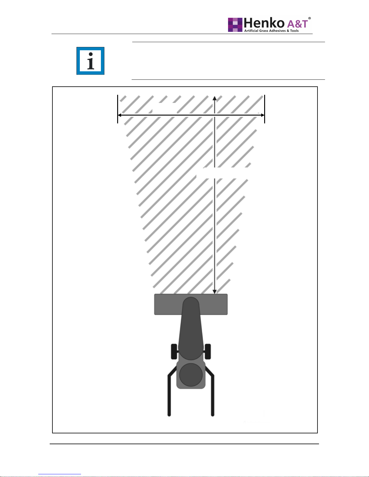
The danger zone is shown in the sketch (see Fig. 1, on the next
page):
A top view of the Brush Machine is shown. The shaded area is
the danger zone.
The danger zone on the right side and left side is determined
through the width of the Brush Machine. Toward the front side
of the Brush Machine the length of the danger zone is 5 m in
front of the Brush Machine.
Safety
Page 10
Page 10 of 33
18-8-2014
Henko A&T B.V.
NOTE
When swinging the Brush Machine to the right or left this change in
direction also applies for the danger zone.
Safety
A
Fig. 1:
Danger zone
2.5 m
5 m ahead of the Brush Machine
Page 11

Henko A&T B.V. 18-8-2014 Page 11 of 33
1.6 Work clothing
WARNING!
Unsuitable, loose work clothing, bandanas, ties, and scarves
can be caught by the Brush Machine and pulled in.
Severe injuries are the result.
Therefore:
When operating the Brush Machine, and for maintenance
and repair tasks, always wear suitable tight-fitting work
clothing.
Special protective clothing is not necessary for work with the
Brush Machine. However always wear tight-fitting work clothing
that cannot get caught in the Brush Machine, and that is
appropriate for the respective weather, as well as sturdy shoes.
For commercial use the owner must ensure that suitable work
clothing is selected and also worn.
1.7 Safety devices and protective devices
1.7.1 Safety switch
The switch levers for traction drive and rotation of the Brush
Machine are designed as safety switches. By pressing down
the switch levers on the steering arm handles, the traction drive
and the rotation of the sweeping broom will be switched on.
To bring the Brush Machine to a standstill, it suffices to
release the switch levers.
1.7.2 Brush Machine deck
The Brush Machine deck is mounted like a protective sheet
metal element above the sweeping brushes and prevents
operating personnel from being hit by thrown up sweepings.
1.7.3 Protective cover
The belt drives in the interior of the Brush Machine are
considered danger zones and are protected against access by
the front protective cover and the housing.
Safety
Page 12

Page 12 of 33
18-8-2014
Henko A&T B.V.
1.8 Safety regulations and accident prevention
regulations
Comply with the following instructions to avoid injury and material
damage. In addition, for commercial use comply with the safety
and accident prevention regulations issued by the Employers
Liability Insurance Associations.
Only operate the Brush Machine with properly mounted
safety devices and protective devices (see section 1.7).
These devices may only be dismounted for maintenance and
repair tasks. After concluding these tasks the safety devices
and protective devices must be immediately remounted.
Otherwise there is significant danger of injury.
Only use the Brush Machine for its intended use, otherwise
dangerous situations can occur with serious or fatal injuries
as the result (intended use: see section 1.1).
Due to poor lightning conditions during operation a number of
dangers can occur. Only operate the Brush Machine if there
is adequate lighting.
For sweeping tasks along walls there is danger of hand
scrape injuries. Avoid touching the walls with your hands and
wear protective gloves.
Maintenance and repair tasks may only be executed by the
specialist dealer or by specialised personnel.
High voltage on the ignition cable and spark plug connector!
Always switch the sweeper off with the fuel control lever,
before performing tasks on the ignition cable or spark plug
connector.
Comply with the instructions on the safety stickers that are
located on the Brush Machine. Safety stickers must not be
removed. If they have become illegible or have been lost,
they must be replaced (meaning of the stickers: see section
1.10). Contact your specialist dealer to order new stickers.
Wear tight-fitting clothing. Long hair must be tied back.
Safety
Page 13

Henko A&T B.V. 18-8-2014 Page 13 of 33
Do not operate the Brush Machine in faulty condition;
significant injury hazards can occur. If faults occur switch off
the Brush Machine and initiate the repair.
Execution of the specified maintenance and repair tasks is
part of intended use of the Brush Machine; intended use
particularly includes compliance with the maintenance
intervals. If you do not execute these tasks, faultless
function cannot be ensured. Dangers for personnel and
objects can occur. We recommend that you keep
maintenance logs.
Switch off the Brush Machine prior to performing repair
tasks, including cleaning tasks. Ensure that no other person
can restart the Brush Machine (e. g. pull off the spark plug
connector). Otherwise there is danger of injury.
Only use original spare parts and accessories that are
approved by the manufacturer. The use of other parts voids
the liability for the ensuing consequences.
1.9 Disposal
After its service life, only have qualified specialists dispose of
the Brush Machine. The manufacturer assumes no liability for
damage that occurs due to improper disposal.
Safety
Page 14
Page 14 of 33
18-8-2014
Henko A&T B.V.
1.10 Safety signs on the Brush Machine
Warning!
Danger of injury due to ignorance of the danger zones.
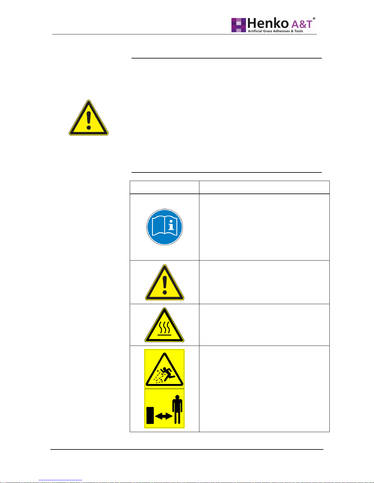
The stickers attached on the Brush Machine contain warnings of
specific dangers as well as instructions for correct operation. The
stickers supplement the instructions specified in this manual.
Therefore:
Always comply with the warnings affixed on the sweeping
machine.
Do not remove any warning stickers
Replace warning stickers that come off of the machine or that
have already been lost.
Stickers
Meaning
Before using the Brush Machine, the
operating manual must be read. All
information contained in the operating
manual must always be complied with.
Position: On the rear of the machine in the
operator’s field of vision.
Warning - general dangers.
Position: On the rear of the machine in the
operator’s field of vision.
Warning - hot surface.
Position: On the motor.
Warning - thrown up sweepings.
Maintain distance.
Position: On the rear of the brush deck.
Safety
Page 15

Henko A&T B.V. 18-8-2014 Page 15 of 33
2 Description
Description
The brush on this engine driven device is for brushing artificial
grass both for installation and maintenance and has been
especially designed and made to our own specifications.
The special fibers in the brush prevent any damage to the
artificial grass fibers in the turf while still performing the proper
cleaning and comb action.
It will make the seams less visible, remove debris, comb the
fibers, and brush the infill (if applicable).
The 4-stroke petrol engine requires little maintenance and is
very economical. Wide handle- bars give good directional
control and good grip.
Replacement brushes can also be ordered at Henko A&T B.V.
Page 16
Page 16 of 33
18-8-2014
Henko A&T B.V.
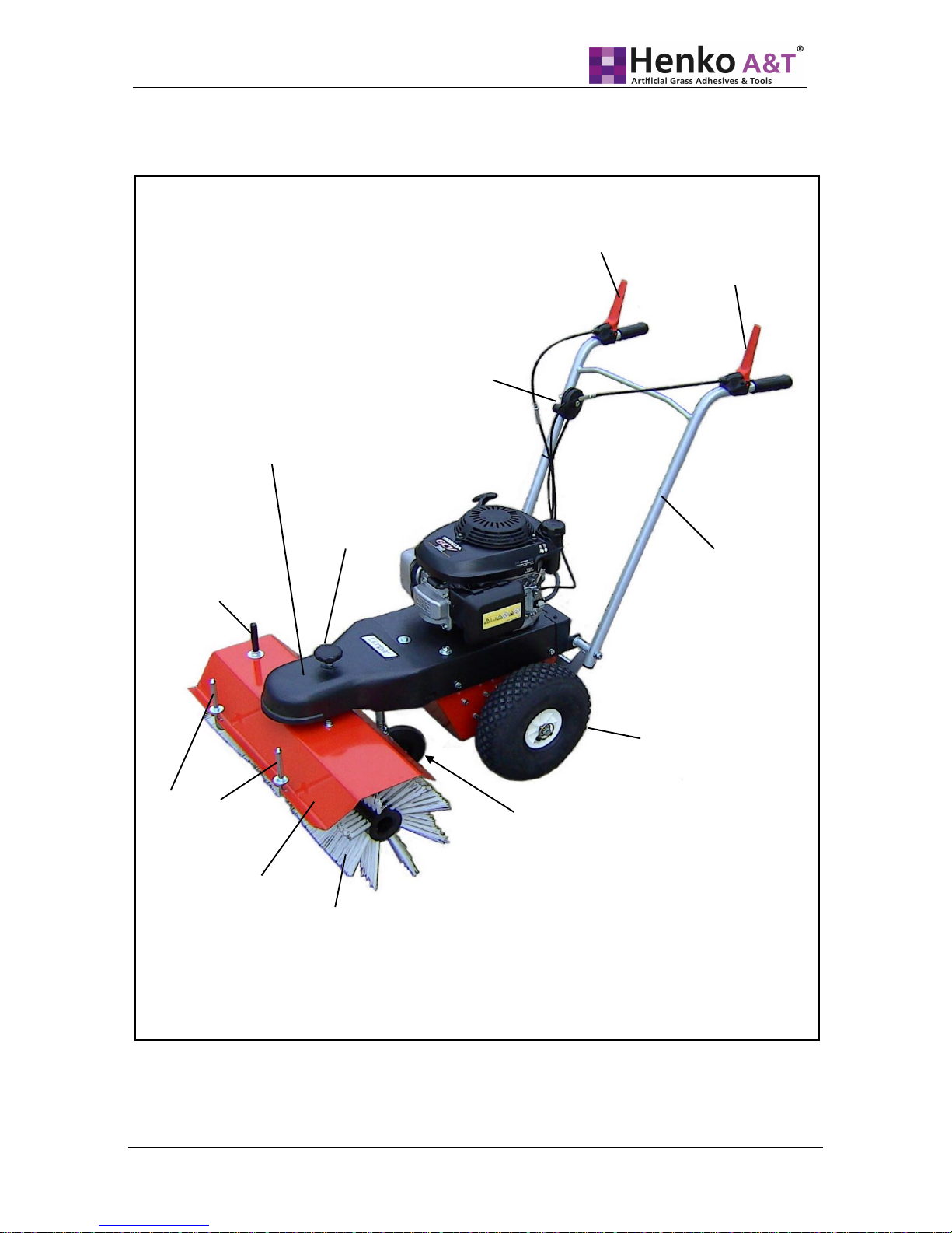
2.2 Overview
Fig. 3: Components and operating elements
Switch lever –
traction drive
Switch lever –
brush drive
Trunnion
(Side adjustment
– Brush Machine)
Accessory
receptacles
Brush Machine deck
Sweeping brush
Support
wheel
Drive wheel
Fuel control lever
and motor stop
Description
Steering arm
Knob
(Locking
mechanism for
side adjustment of
Protective cover
Page 17

Henko A&T B.V. 18-8-2014 Page 17 of 33
2.3 Technical data
Dimensions, weight, travel speed, motors
Work width
70 cm
Brush diameter
25 cm
Weight
45 kg
Travel speed
3.3 km/h
Motor
Honda GCV 135 or
Briggs & Stratton DOV
Hand/arm vibrations on the Brush Machine
Vibration total value
(Honda motors)
a
hwd
= 3.5 m
-2
Vibration total value
(Briggs & Stratton motor)
a
hwd
= 3.3 m
-2
Noise emission value of the Brush Machine
Sound power level
(Honda motor)
L
WAd
= 95 dB(A)/1pW
Sound power level
(Briggs & Stratton motor)
L
WAd
= 94 dB(A)/1pW
Sound pressure level
at the operator’s ear
(Honda motor)
L
pAd
= 84.5 dB(A)/20µPa
Sound pressure level
at the operator’s ear
(Briggs & Stratton motor)
L
pAd
= 84 dB(A)/20µPa
Description
Page 18
Page 18 of 33
18-8-2014
Henko A&T B.V.
3 Commissioning
CAUTION!
Danger of injury and danger of material damage due
to improper assembly of the Brush Machine.
Therefore:
The completion and all necessary adjustments, incl. trial
run are included in the scope of delivery and must be
executed by the specialist dealer prior to transfer to the
customer!
We recommend that two people assemble the Brush
Machine.
3.1 Unpacking
Place the packed Brush Machine on a level floor
Open the box on the top
Cut open the 4 corners of the box to the floor.
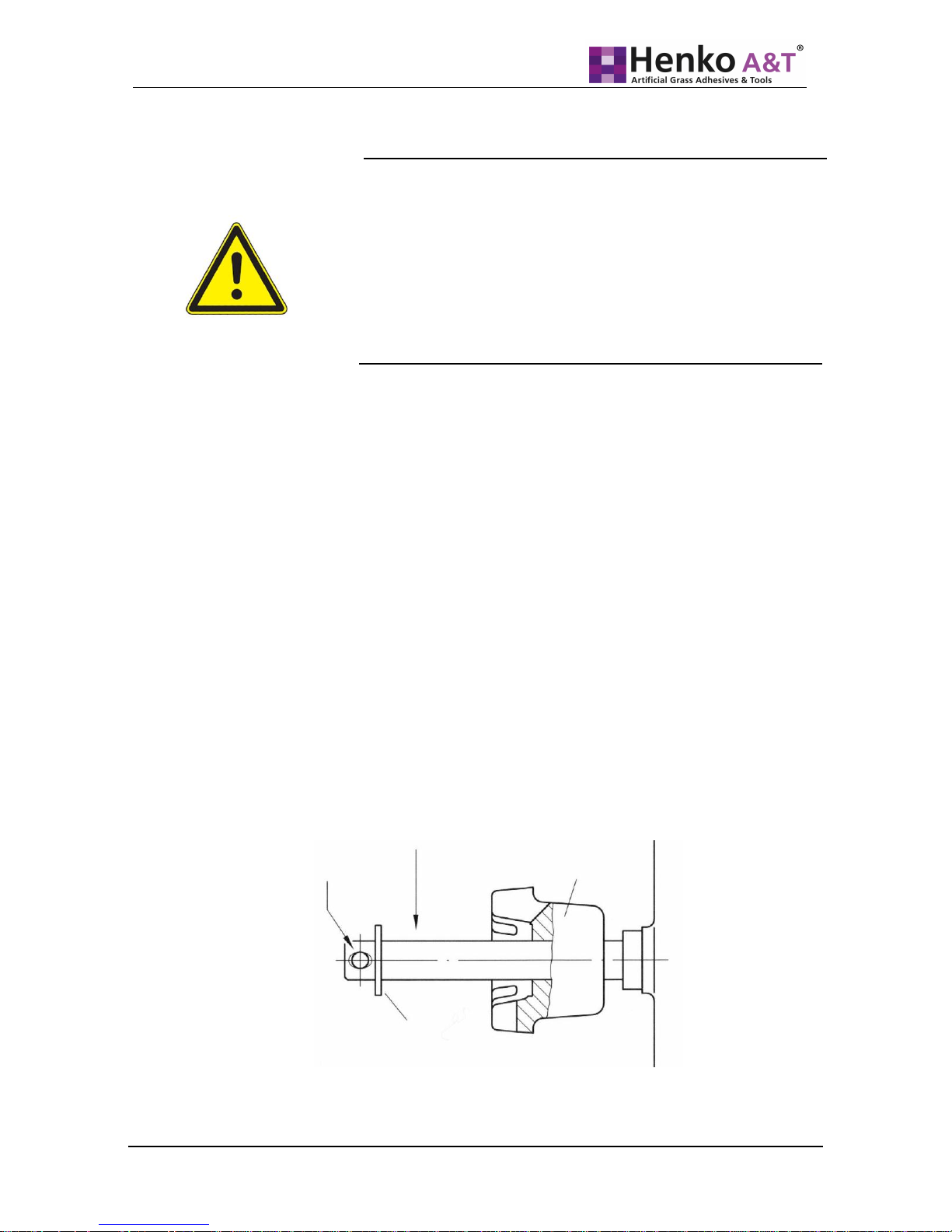
Mount the drive wheels (see the assembly instructions
for the drive wheels included as a separate sheet in the
box, or at the end of this page)
Set up the steering arm in accordance with section
3.2 and roll the Brush Machine out of the packaging.
Dispose of the packaging in accordance with the waste
disposal regulations issued by your municipal
administration.
Wheel
Here
hinged pin
Freewheel /
tappet
Washer
Commissioning
Fig. 4:
Assembly – drive wheels
Page 19
Henko A&T B.V. 18-8-2014 Page 19 of 33
3.2 Making the steering arm operational
The Henko 671 Brush Machine has an adjusting possibility for
the height of the steering arm handles. A medium height that
most users perceive as comfortable has been specified in the
factory. The steering arm is folded forward for transport. To
establish operational readiness the steering arm must be
straightened up and bolted to a support bracket.
CAUTION!
Danger of injury and danger of material damage when raising the
steering arm.
When lifting up the steering arm there is a crush hazard between
steering arm and motor.
Bowden cables can be pinched and damaged when lifting up the
steering arm.
Therefore:
Carefully lift up the steering arm.
When lifting up the steering arm pay attention to the Bowden
cables.
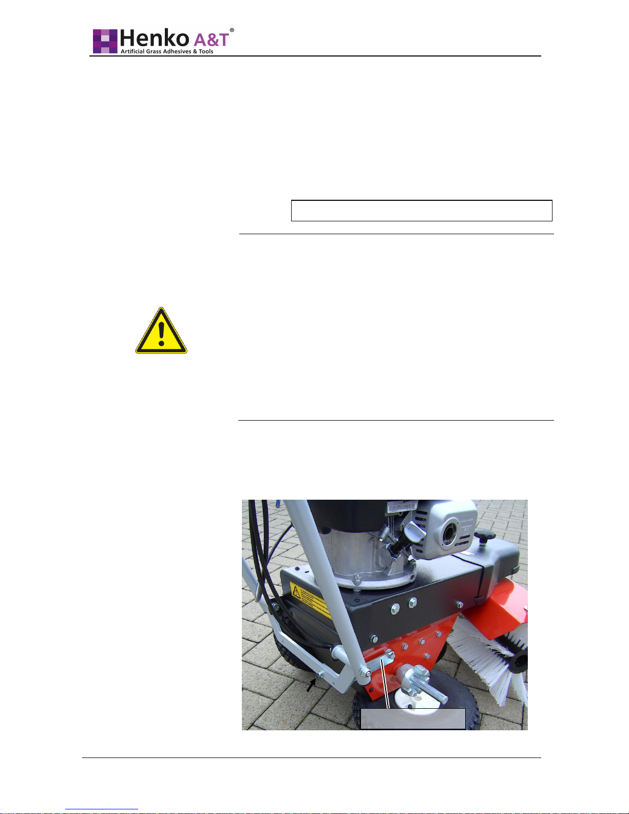
Behind the rear wheel a support bracket is bolted onto the
housing; it extends around the rear and has a bore that is
aligned flush with a bore in the lower steering arm crossmember
(see Fig. 5).
Commissioning
Task to be performed by the specialised workshop!
Fig. 5:
Steering arm fastening –
lower
Support bracket
Bolt here
Page 20
Page 20 of 33
18-8-2014
Henko A&T B.V.
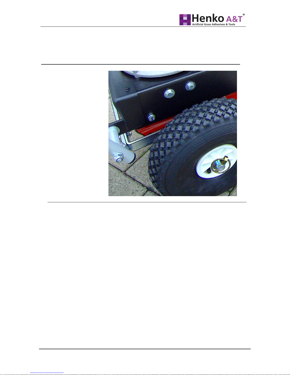
Use the pre-mounted M6 screw to fasten the steering arm on
the support bracket. Washers must be placed under the
screw head and under the stop nut.
See Fig. 6.
Commissioning
Fig. 6:
Correct installation –
steering arm / support
bracket
Page 21

Henko A&T B.V. 18-8-2014 Page 21 of 33
4 Operation
Prior to operation always read the instructions in the Safety
chapter (see chapter 1)!
WARNING!
Danger of injury when operating the Brush Machine.
Thrown up sweepings can hit and injure persons in the danger
zone.
Therefore:
Ensure that no one is in the danger zone (see Fig. 1).
Only switch on traction drive and brush rotation after this
has been done.
Always observe the danger zone during operation.
Stop the traction drive and brush rotation if people enter the
danger zone during operation.
WARNING!
Life-threatening danger due to harmful sweepings.
When dealing with harmful sweepings (e. g. due to radioactive
or biological contamination) there is danger of fatal illness due
to inhalation of dust.
Therefore:
Do not use the Brush Machine for harmful sweepings.
Operation
Page 22

Page 22 of 33
18-8-2014
Henko A&T B.V.
DANGER!
Life-threatening danger due to movements of the Brush
Machine.
When operating the Brush Machine on slopes, the Brush
Machine can start moving without control, due to gravity.
Therefore:
For sweeping tasks on sloping terrain always bear in mind that
there is a possibility of the machine rolling off.
Switch on the brush drive and use it as a brake.
If possible, guide the Brush Machine on slopes transverse to
the direction of the slope.
Do not use the Brush Machine on terrain with a slope of
more than 37% (20 degrees).
WARNING!
Danger of injury due to dismounted or non-functioning protective
devices and safety devices.
If protection and safety devices are converted, bypassed or
dismounted’, they no longer fulfil their function.
Therefore:
Do not convert or bypass protective devices and safety devices.
Always remount protective devices and safety devices (if
removed, for example, for service and maintenance purposes).
CAUTION!
Danger of burn injuries on the motor at operating temperature.
Therefore:
Do not touch the motor during operation.
Operation
Page 23

Henko A&T B.V. 18-8-2014 Page 23 of 33
CAUTION!
Danger of injury and danger of material damage if the Brush
Machine is operated in faulty condition.
Therefore:
Perform a visual inspection prior to each start of the sweeping
machine.
Prior to each start check the operating elements for firm seat
and function.
WARNING!
Danger of poisoning when operating the Brush Machine in
closed rooms.
When operating the Brush Machine in closed rooms there is
danger of poisoning due to exhaust gases and petrol fumes.
Therefore:
Only operate the Brush Machine outside of closed rooms.
WARNING!
Danger of poisoning and danger of material damage when
parking the hot Brush Machine in closed rooms.
When parking the hot Brush Machine in closed rooms there is
danger of explosion due to petrol fumes.
Therefore:
After operation let the Brush Machine cool down.
Only park it in a closed room after it has cooled down.
WARNING!
Danger of injury and danger of material damage if the Brush
Machine is operated by unauthorised persons.
Therefore:
After operation store the Brush Machine in a closed room.
Operation
Page 24
Page 24 of 33
18-8-2014
Henko A&T B.V.
4.1 Preparatory activities
4.1.1 Adjusting the height of the Brush Machine
The Brush Machine should be pressed in approx. 1.5 cm in
operation.
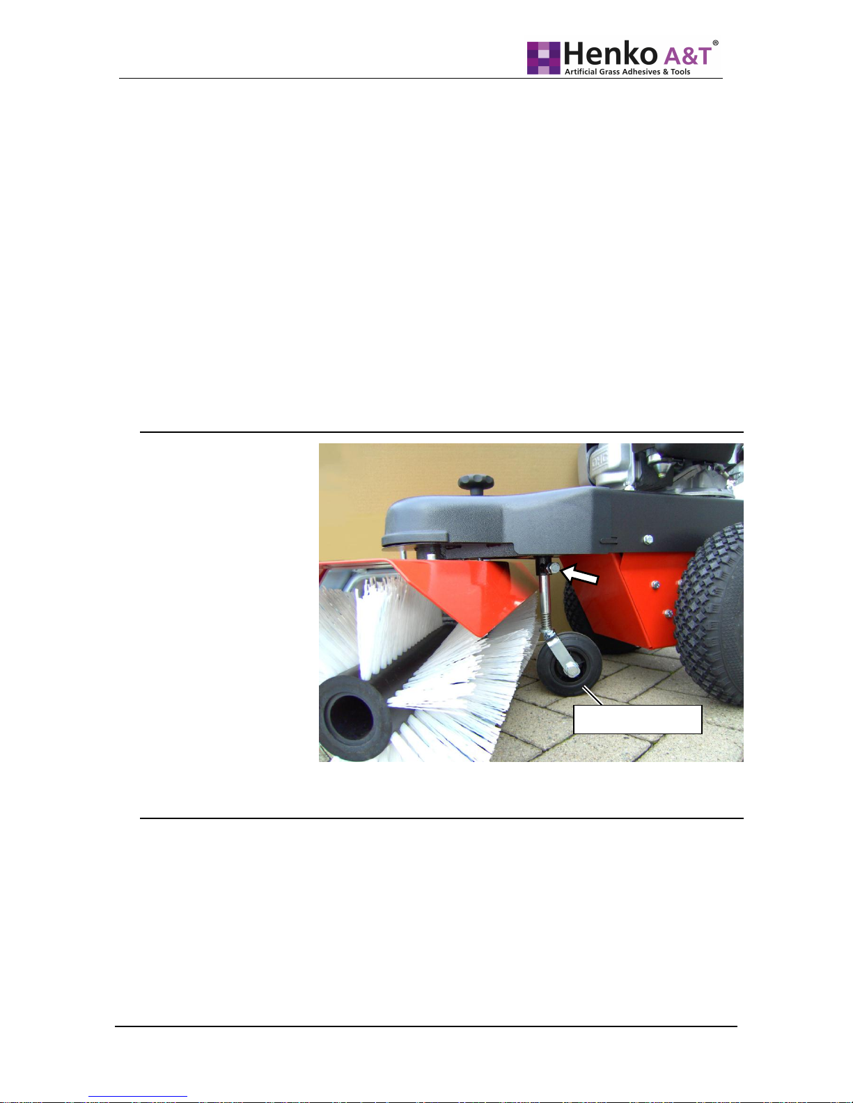
Unscrew the lock nut and clamp screw on the height
adjustment element for the support wheel (see Fig. 7)
Press or lift the brush deck to obtain the setting on the
brush deck.
Fix the support wheel adjustment element in place with the
clamp screw.
If you need help with the adjustment contact your specialised
workshop.
4.1.2 Checking the motor oil level
Prior to each start of the motor, check the oil level (see the
operating manual provided by the motor manufacturer in the
sub-package for the Brush Machine).
Operation
Fig. 7: Support wheel with clamp screw (arrow)
Support wheel
Page 25

Henko A&T B.V. 18-8-2014 Page 25 of 33
4.1.3 Filling fuel
Prior to the first start of the motor, fill at least half full with fuel
(see the operating manual provided by the motor manufacturer
in the sub-package for the Brush Machine).
WARNING!
Danger of injury and danger of material damage if fuel is filled
during operation.
When fuel runs over the hot motor and the exhaust, highly
flammable gases occur.
Therefore:
Switch off the motor (see section 4.2.2).
Let the motor cool.
Only top up with fuel after the motor has cooled.
4.2 Sweep operation
NOTE
We recommend that you always sweep in the wind direction.
This prevents thrown up sweepings from hitting the operator or
fouling the motor. For winter service in particular, the motor
function can be impaired.
4.2.1 Starting the motor
Ensure that the spark plug connector has not been pulled
off.
Open the fuel cock (if present, see the operating manual
provided by the motor manufacturer in the sub-package
for the Brush Machine).
Place the fuel control lever on “Max” (choke position).
Start the motor with a forceful pull on the starting rope.
After a few seconds set the fuel control lever back far
enough that the motor no longer runs in choke, but in the
full load range.
Operation
Page 26
Page 26 of 33
18-8-2014
Henko A&T B.V.
4.2.2 Stopping the motor
Slide the fuel control lever in the “Stop” direction until the
motor switches off.
Close the fuel cock (if present).
4.2.3 Switching the traction drive on and off
CAUTION!
Danger of injury due to the machine falling when switching on
traction drive.
When switching on traction drive the machine starts to move
abruptly.
Therefore:
Be aware of the abrupt start-up of the Brush Machine.
Comply with the requirements imposed on operating
personnel (See section 1.4).
Press the red lever on the left steering arm handle
downward (see Fig. 3)
The Brush Machine starts up.
Release the red lever on the left steering arm handle.
The lever flips upward and the Brush Machine stops
moving.
4.2.4 Switching the sweeping brushes on and off
CAUTION!
Danger of injury due to the machine falling when switching
on the Brush Machine drive.
When switching on the Brush Machine drive the Brush
Machine moves toward the operator.
Therefore:
Bear in mind that the Brush Machine moves toward you
when switching on the brush drive!
or:
Operation
Page 27
Henko A&T B.V. 18-8-2014 Page 27 of 33
First switch on the traction drive of the Brush Machine,
and then switch on the Brush Machine drive.
Comply with the requirements imposed on operating
personnel (See section 1.4).
Press the lever on the right steering
arm handle downward
(see Fig. 3)
The Brush Machine starts to rotate.
Release the lever on the right steering arm handle.
The lever flips upward, the rotation of the Brush Machine stops.
4.2.5 Side adjustment of the Brush Machine
To brush the sweepings to one side, the Brush Machine can be
positioned diagonally.
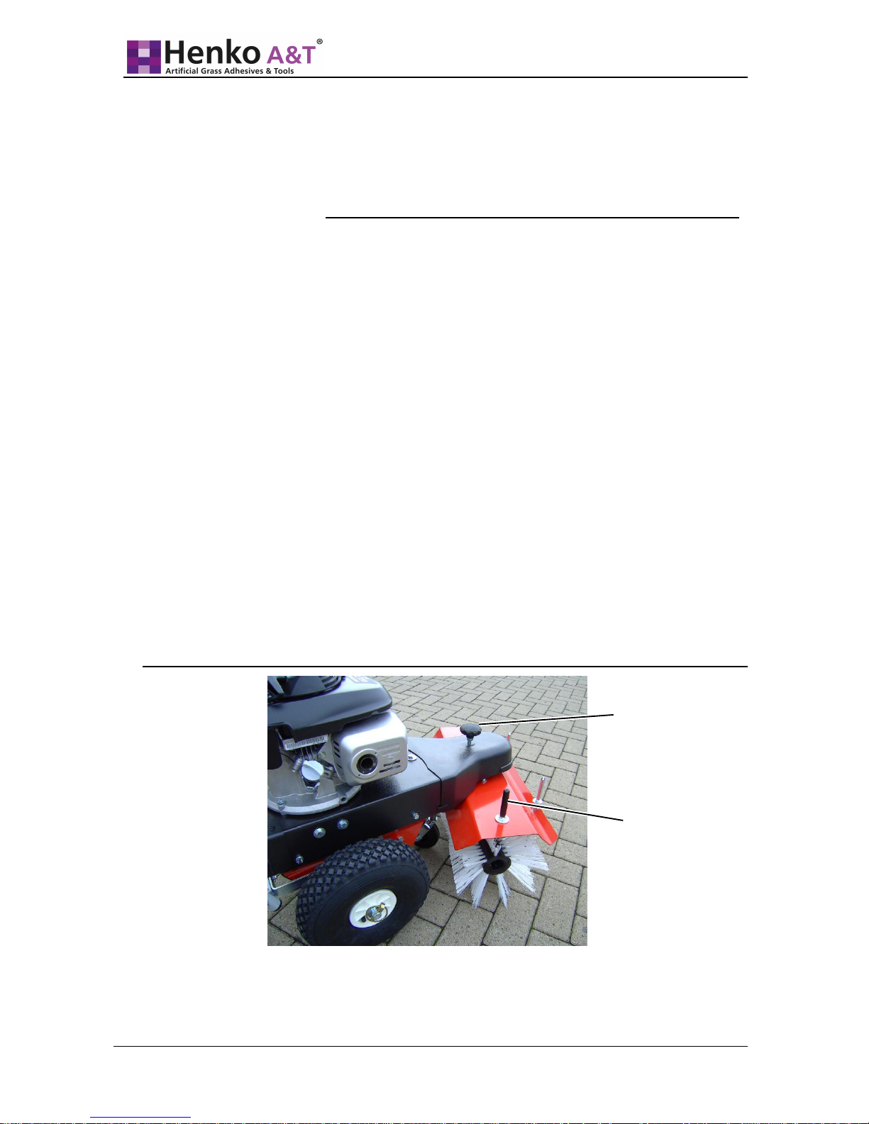
Go to the front of the brush deck and pull out the knob that
is above the protective cover until the catch is released
(see Fig. 8).
Grasp the trunnion on the right side of the brush deck
(Fig. 8) and swing the deck into the desired position.
Release the knob and move the brush deck a little bit
further until the position engages.
Operation
Fig. 8: Positioning the Brush Machine diagonally
Knob
Trunnion
Page 28

Page 28 of 33
18-8-2014
Henko A&T B.V.
5 Maintenance and repair
Execution of maintenance and repair tasks requires
specialised skills and an equipped workshop.
As the manufacturer we prescribe that these tasks must
be performed in a qualified workshop!
5.1 Safety guidelines for maintenance and
repair
Prior to maintenance always comply with the instructions in the
“Safety” chapter as well (see chapter 1).
WARNING!
If other persons unexpectedly start up the Brush Machine,
there are a number of injury hazards.
Therefore:
Unplug the spark plug connector for maintenance tasks.
WARNING!
Danger of injury due to dismounted protective devices and
safety devices.
If protective devices and safety devices are dismounted they no
longer fulfil their function.
Therefore:
Always remount protective devices and safety devices after
they have been dismounted (for example, for service and
maintenance purposes).
WARNING!
The Brush Machine poses significant hazards for nonspecialised persons.
Therefore:
Only have maintenance and repair tasks executed by the
specialist dealer. This particularly applies for maintenance and
repair tasks on the motor and V-belt drives.
Maintenance and repair
Page 29

Henko A&T B.V. 18-8-2014 Page 29 of 33
DANGER!
Use of inferior-quality spare parts can result in injury and material
damage.
The use of spare parts other than original spare parts or other
than spare parts and accessories approved by the manufacturer
voids the liability for the ensuing consequences.
Therefore:
Only use original spare parts and accessories that are
approved by the manufacturer.
ATTENTION!
Improper maintenance can damage the Brush Machine.
Therefore:
Only have maintenance and repair tasks executed by the
specialist dealer.
This also applies for replacement of the Brush Machine.
5.2 Regular maintenance tasks
For maintenance tasks that affect the motor refer to the
documentation provided by the motor manufacturer.
Contact your specialist dealer for maintenance tasks that must
be executed by a specialist.
5.2.1 Maintenance schedule
Interval
Activity
see
Before each
use
Check the motor oil level
Operating manual
provided by the
motor
manufacturer
Check the Bowden cables for ease of movement
5.2.3
Visual inspection of the Brush Machine for damage,
particularly ignition cable and spark plug connector
Check tyre pressure
5.2.4
as needed
Cleaning the Brush Machine
5.2.5
Check and clean the air filter
5.2.6
Maintenance and repair
Page 30

Page 30 of 33
18-8-2014
Henko A&T B.V.
5.2.2 Maintenance records
Enter the executed maintenance tasks in the table provided for
this purpose. (See section 5.3.) This makes the maintenance
history traceable.
For more extensive records concerning tasks performed on the
Brush Machine we recommend that you keep a separate list.
5.2.3 Check the Bowden cables for ease of movement
WARNING!
Bowden cables that do not move easily can cause uncontrolled
movements of the Brush Machine, severe injury and material
damage.
Therefore:
If the Bowden cables do not move easily, do not place the
sweeping machine in service.
Contact your specialist dealer and have the sweeping
machine repaired.
Bowden cables for traction drive and brush drive
Press down the switch lever for traction drive.
You must be able to push down the switch lever to the
steering arm handle with light resistance.
Release the switch lever for the traction drive.
The switch lever must spring back into its original position.
Repeat the procedure with the switch lever for the brush
drive.
Have the repair performed by your specialist dealer if one or
both switch levers are hard to move or do not spring back into
their original position.
Bowden cable of the fuel control lever
Place the fuel control lever on “Max”.
Place the fuel control lever on “Min” and in this process
observe the counter lever on the carburettor (see the
operating manual provided by the motor manufacturer in
the sub-package of the Brush Machine).
Maintenance and repair
Page 31

Henko A&T B.V. 18-8-2014 Page 31 of 33
You must be able to move the fuel control lever with light
resistance. The counter lever on the carburettor must follow the
executed movement.
Have the repair performed by your specialist dealer if the
Bowden cable does not function as described above.
5.2.4 Checking the tyre pressure
The inflatable tyres of the Brush Machine have conventional
automobile valves.
Set the tyre presser of the drive wheels to 1.8 bar.
5.2.5 Cleaning the Brush Machine
ATTENTION!
Cleaning the Brush Machine with a high-pressure cleaner can
damage the seals, bearings, and joints of the Brush Machine.
Therefore:
Do not clean the Brush Machine with a high-pressure
cleaner
Clean the Brush Machine as needed with a soft water spray
and auto care agents.
5.2.6 Checking and cleaning the air filter
If you use the Brush Machine in a dusty environment, have
your specialist dealer show you how to check the air filter.
Maintenance and repair
Page 32

Page 32 of 33
18-8-2014
Henko A&T B.V.
5.3 Maintenance and repair verifications
Executed maintenance tasks
Date
Signature
Comments / executed tasks
Maintenance and repair
Page 33

Henko A&T B.V. 18-8-2014 Page 33 of 33
6 Decommissioning and preservation
Contact your dealer if you have questions concerning
decommissioning and preservation.
7 Faults and fault correction
WARNING!
Danger of severe injury due to improper execution of repair
tasks.
Therefore:
Only have repair tasks performed by a specialised
workshop.
If there are faults in the operation of the Brush Machine,
proceed on the basis as specified in the fault table below. If
there are faults that cannot be corrected based on the
instructions and measures cited for fault correction, contact
your specialised workshop.
Fault
Possible cause
Measures
The Brush Machine
does not start up.
Fuel control lever is not in “Max”
(choke) position.
Place the fuel control lever in the
“Max” position.
Spark plug connector is pulled off.
Fit on the spark plug connector.
No fuel in the tank.
Fill with fuel.
Gas cock is closed.
Open gas cock.
Often the sweeping roller
sticks.
Bowden cable is not correctly
adjusted.
Contact the specialist dealer.
The Brush Machine
does not move straight
ahead.
Air pressure varies in the tyres.
Correct the air pressure in the
tyres.
Freewheel units of the wheel drive
do not work synchronously.
Synchronise the wheel drive
through a short, forceful pull on
the steering arm.
Decommissioning and preservation
Henko A&T B.V.
Graafschap Hornelaan 184, 6004HT Weert, The Netherlands
Tel: +31 (0)495 63 30 10, Fax: +31 (0)495 58 67 35
[email protected], www.henko-at.nl
 Loading...