

Henkel Loctite, MMD System 1000 Machine Manual
Henkel Corporation
MMD System 1000
Machine Manual

SAFETY
• Always wear safety glasses when operating.
• 100-PSI maximum inlet air pressure. Use a known
regulated dry air source only.
• Hazardous Noise! Agitator air motors run at 86 dBA.
Pumps cycle is peak 75 dBA. Always wear hearing
protection.
• The installation of the SYSTEM 1000 should include a
system air disconnect accessible by the operator.
• Read all material manufacturer’s product information. Always
follow material manufacturers specific recommendations
regarding dispensing even if they may differ from these
general instructions.
• Keep the MSDS accessible to the work area as it lists
valuable emergency information.
• Consult local, state and federal laws before disposing of
mixers or material.
• Do not operate if any of the SYSTEM 1000
components are missing or damaged.
• Danger Labels: Indicate an
imminently hazardous situation, which,
if not avoided, could result in death or
serious injury.
• Warning Labels: Indicate potentially
hazardous situations which, if not
avoided could result in death or
serious injury.
• Caution Labels: Indicate an unsafe
practice that may result in moderate or
minor injury.
• Notice Labels: State a company
policy.
V
Safety Precautions
This manual provides installation, operation, and maintenance instructions for Loctite meter, mix, and dispense
machines. Read this manual before you install and operate your machine. Use your machine only as directed.
Safety Terms within our manuals
Cautions are given where failure to observe the instruction could result in damage to the equipment, associated
equipment, and/or process. Warnings are given where failure to observe the instruction could result in injury or death
to people.
Some examples follow.
Snuff-back can be monitored with D
MODE in AUTO, but must be
adjusted with DV MODE in OPEN
Safety Labeling on our machinery
All our machines carry the following safety labels wherever necessary:
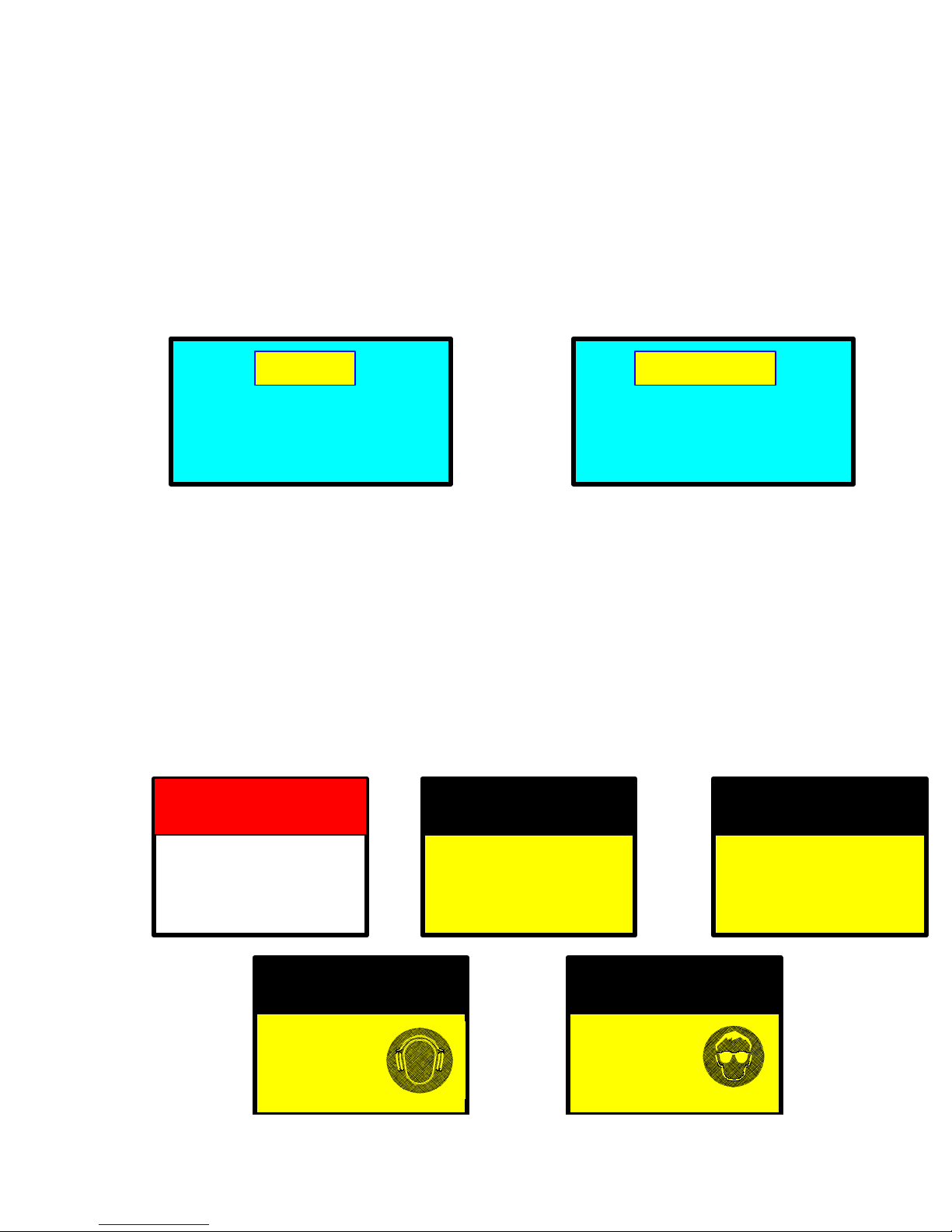
Danger Labels
•
injury.
Warning Labels
•
injury.
Caution Labels
•
Notice Labels
•
DANGER
DO NOT OPERATE THIS
MACHINE WITH
GUARD(S) DETACHED
Caution
indicate an imminently hazardous situation, which, if not avoided, could result in death or serious
indicate potentially hazardous situations which, if not avoided, could result in death or serious
indicate an unsafe practice that may result in moderate or minor injury.
state a company policy. Some examples are:
CAUTION
WEAR EAR
PROTECTION
WARNING
UNPLUG MACHINE
BEFORE OPENING
ENCLOSURE
Make sure EMERGENCY STOP is
locked in before manually aligning
the ratio block to the ratio beam
CAUTION
WEAR EYE
PROTECTION
WARNING
PROVIDED AT MACHINE
SUPPLY TERMINALS
NOTICE
OVERCURRENT
PROTECTION
.

Table of Contents
WARRANTY.................................................................................................................................................1
SYSTEM 1000 GENERAL DESCRIPTION ..............................................................................................2
DIAGRAMS OF COMMON VALVES AND PARTS...............................................................................3
MACHINE FEATURES...............................................................................................................................5
REASSEMBLY AND INSTALLATION....................................................................................................6
ADJUSTING THE SHOT SIZE .................................................................................................................. 7
LOADING THE MACHINE WITH MATERIALS ..................................................................................8
PRIMING THE MATERIAL VALVES .....................................................................................................9
PHASING THE PUMPS ............................................................................................................................10
RATIO CHECK..........................................................................................................................................11
RATIO ADJUSTMENT ............................................................................................................................. 12
DAILY OPERATION.................................................................................................................................13
SHUTDOWN...............................................................................................................................................14
PISTON REPLACEMENT........................................................................................................................15
PERIODIC MAINTENANCE ...................................................................................................................16
TROUBLESHOOTING .............................................................................................................................17
ADDITIONAL INFORMATION ..............................................................................................................21
PUMP REBUILD......................................................................................................................................A-1

WARRANTY
PROPRIETARY EQUIPMENT AND COMPONENTS
MANUFACTURED BY SELLER
The warranties contained herein are not made in regard to auxiliary equipment and components (see Section below). Unless
otherwise specifically stated in writing, warranties are limited to the following: All proprietary goods designed, manufactured and
sold by Seller are guaranteed against defective workmanship or material for a period of three (3) years after date of shipment
from the factory, provided the goods were operated under the condition for which they were sold. This warranty does not cover
seals or components that are out of specification due to normal wear and tear or improper maintenance of the equipment. All
claims pursuant to the warranties must be made within such three (3) year period. If Buyer claims the goods are defective
within the three (3) year period, Buyer shall notify Seller immediately, in writing. Seller may inspect, by authorized agent, the
defective claim or issue shipping instructions for return of the goods to its factory. Seller shall have the option, at its sole
discretion, if the goods are found to be defective, to correct the defect or defects by repair or replacement or refund the
purchase price. Seller's obligation, with respect to such goods, shall be limited to the replacement or repair F.O.B. Seller's
facility, or refund of the purchase price, and in no event shall Seller be liable for consequential or special damages, or for
transportation installation, adjustment or other expenses which may arise in connection with such goods. The liability of Seller
arising out of supplying said goods and services, or their use, whether on warranties or otherwise, shall not in any case exceed
the cost of the equipment and parts involved, and upon the expiration of said three (3) years, all such liabilities shall terminate.
Seller assumes no liability for damages or expenses of any character, including those arising out of the installation, use or
resale of such goods. No representation or other affirmation of fact not set forth herein, including, but not limited to, statements
regarding capacity, or suitability for use, or performance of the goods, shall be deemed to be a warranty or representation by
Seller for any purpose, nor give rise to any liability or obligation of Seller whatsoever. NO WARRANTY OR GUARANTEE,
EXPRESSED OR IMPLIED, INCLUDING ANY WARRANTY AS TO MERCHANTABILITY OR FITNESS FOR ANY PURPOSE,
IS MADE, EXCEPT AS SPECIFICALLY PROVIDED IN THIS AGREEMENT.
AUXILIARY EQUIPMENT AND COMPONENTS
NOT MANUFACTURED BY SELLER
To the extent that auxiliary equipment and components of other manufacturers (e.g. logic control hardware, valves, transfer
pumps, motors, etc.) are included as part of the machine or system it is understood that these products which are not
manufactured by Seller are subject to the original manufacturer’s warranty policy. FURTHER, SELLER MAKES NO
WARRANTIES OR GUARANTEES, EXPRESS OR IMPLIED, INCLUDING ANY WARRANTIES AS TO MERCHANTABILITY
OR FITNESS FOR ANY PURPOSE AND ASSUMES NO LIABILITIES WITH RESPECT TO AUXILIARY EQUIPMENT AND
COMPONENTS WHICH ARE MANUFACTURED BY OTHERS.

SYSTEM 1000 General Description
The SYSTEM 1000 meter, mix, and dispense machine is a ratio proportioning pump designed
specifically to meter two liquids or pastes in a precise ratio. The volumetric positive displacement
piston pump referred to as the Posiload pump is a unique development in the course of pump
design, and because of the ability to interchange pump metering tubes from 10 mm to 55 mm in
0.001 mm increments, allows the selection of many fixed ratios.
The Posiload pump can be used for transfer of precise ratios, metering to a hand held or fixed head
mixer, or injection of the metered materials through a mixer into open or closed molds.
The complete system is totally enclosed and mixing of the liquids only takes place at the final
stage of the equipment within the mixing chamber. Flushing is achieved by an air and solvent
purge system or with one material component with a secondary component bypass.
It is recommended that this manual be read thoroughly by all personnel charged with the
responsibility of operating, maintaining, or cleaning the equipment.
CAUTION
Due to the precise nature of the SYSTEM 1000, we recommend consulting
Henkel’s technical service department
@ (800) LOCTITE before making any major adjustments.
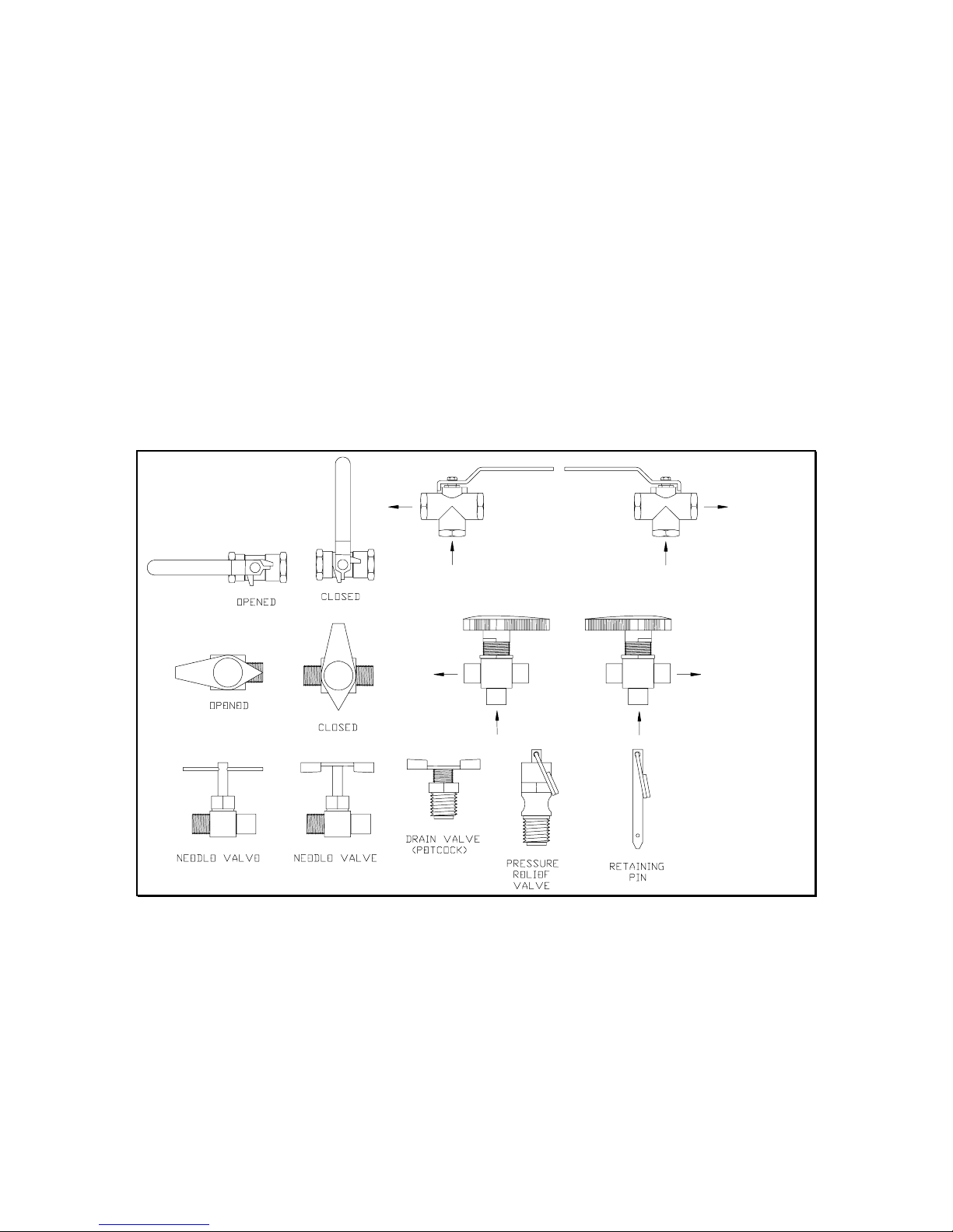
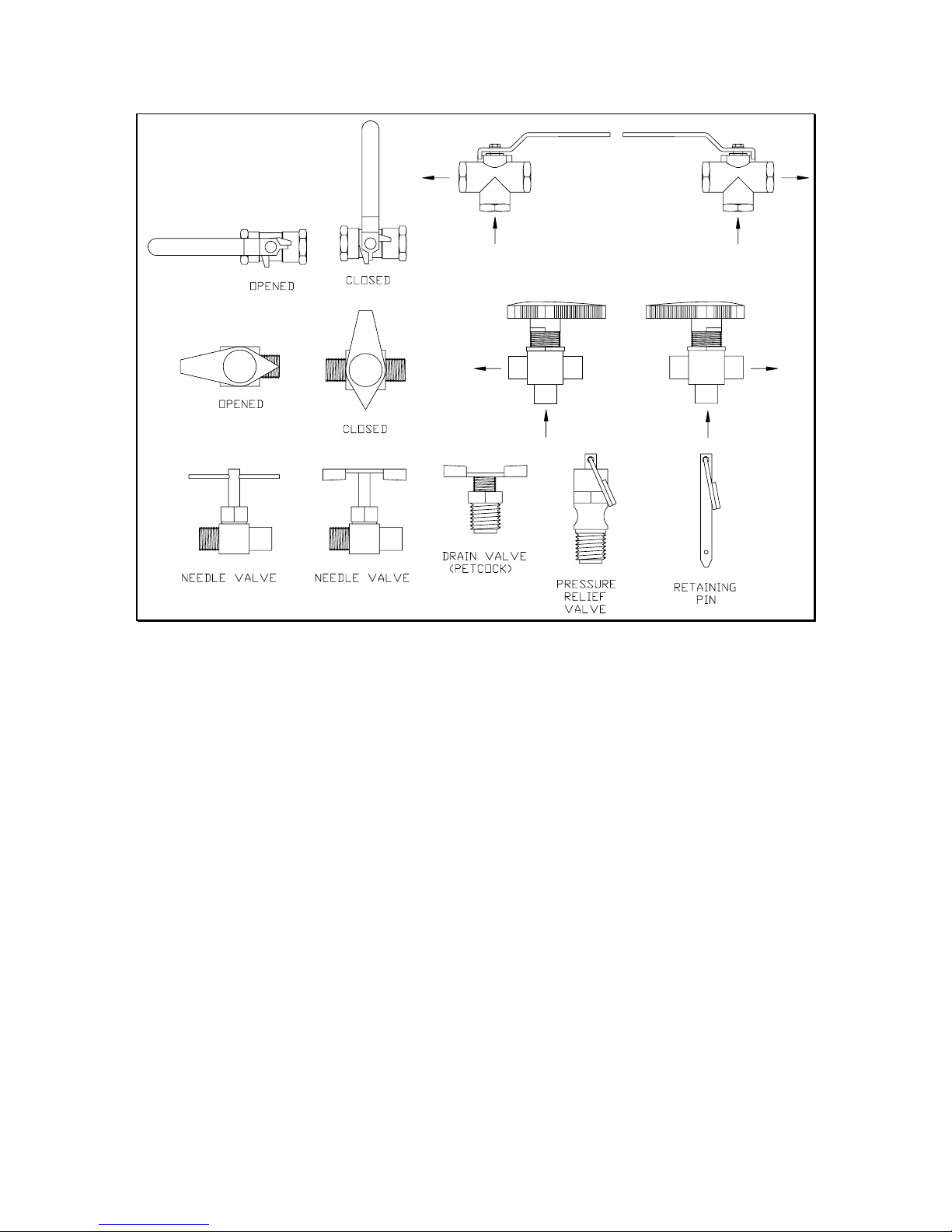
Diagrams of Common Valves and Parts
The below diagrams depict common 2-way and 3-way ball valves and the handle styles are likely
to be encountered on this machine. Also, shown in the following diagrams are miscellaneous parts
likely to be used by this machine. These diagrams are for reference only and may not show all
types and styles of ball valves and other parts.
The 2-way ball valves are shown in the OPENED and CLOSED positions. The 3-way ball valves
are shown in both flow direction conditions (see arrows). In some cases, a 3-way ball valve may
be adjusted to a NEUTRAL position, 90 degrees from the positions shown below. These
NEUTRAL positions may or may not stop flow through the valves and should not be used as
operating positions unless specified elsewhere in this manual. In some cases this machine may
contain a 3-way diverted ball valve which will appear identical to the 3-way ball valves shown
below. In the case of a diverted ball valve, the handle only turns 90 degrees (not 180 degrees) and
there is no NEUTRAL position.
3
Figure 1-Common Ball Valves
4
Figure 2-Common Valves and Parts Cont.
 Loading...