

Henkel 97725, 97715 User Manual

Operating Manual
Bedienungsanleitung
Finespray Applicator HVLP, Extensions
Feinsprühpistole HVLP, Verlängerungen
97715/97725

Content
English
1 Please observe the following................................................................. 3
1.1 Emphasized Sections ...............................................................................3
1.2 Items Supplied .......................................................................................... 3
1.3 Field of Application (Intended Use)........................................................... 3
1.4 For Your Safety......................................................................................... 4
2 Description.............................................................................................. 6
3 Technical Data......................................................................................... 7
4 Setup and Operation............................................................................... 7
4.1 Setup ........................................................................................................7
4.2 Operation.................................................................................................. 8
4.3 Shutdown.................................................................................................. 8
4.4 Return to Operation .................................................................................. 8
5 Care and Maintenance............................................................................ 9
5.1 Care.......................................................................................................... 9
5.2 Changing Nozzle....................................................................................... 9
5.3 Disassembling Valve-Needle .................................................................... 9
6 Troubleshooting.................................................................................... 10
7 Annex..................................................................................................... 11
7.1 Spare Parts Finespray Applicator 97715/97725...................................... 11
7.2 Spare Parts Extensions .......................................................................... 11
7.3 Accessories............................................................................................. 12
Deutsch.................................................................................................. 14
2

1 Please observe the following
1.1 Emphasized Sections
Warning!
Refers to safety regulations and requires safety measures that protect the operator
or other persons from injury or danger to life.
Caution!
Emphasizes what must be done or avoided so that the unit or other property is not
damaged.
As a result of technical development, the illustrations and descriptions in this
operating manual can deviate in detail from the actual unit delivered.
The numbers printed in bold in the text refer to the corresponding position numbers
in the illustration on page 6.
• The point emphasizes an instruction step.
1.2 Items Supplied
1 Finespray Applicator 97715 or 1 Finespray Applicator HVLP 97725
1 Duo Tube, assembled,
1 Operating Manual or
1 Finespray Applicator with Extension
1 Duo Tube, assembled,
1 Operating Manual
1.3 Field of Application (Intended Use)
The Finespray Applicators 97715 and 97725 are high performance spray
applicators and precision tools. They are designed for finest applications of low
viscose Loctite Frekote
High Volume Low Pressure applicator. The HVLP applicator 97725 is working with
lower input and jet pressure and with higher air volume. The atomized spray (jet) is
considerable finer and the overspray is lower.
The applicator 97715 has a 90° flat fan, 97725 a 60° flat fan air cap.
It is not suitable for spraying aggressive fluids, like acids, alkaline solutions,
cleaning agents (chlorinated hydrocarbons) or chemicals.
Always keep clean and observe minimum instructions to maintain a long useful life
of the applicator.
Depending on viscosity of fluid the following nozzle bores are available:
∅ 0.3 and ∅ 0.8 mm (only one size of air cap is required).
– The standard version of the Finespray applicator 97715 has a nozzle bore of
0.5 mm and flat spray pattern air cap with approx. 90° spray angle.
– The standard version of the Finespray applicator HVLP 97725 has a nozzle bore
of 0.5 mm and flat spray pattern air cap with approx. 60° spray angle.
If round spray is required, just replace air cap by a round spray air cap.
Flat spray air cap can be positioned for horizontal, vertical or any in between
position of jet.
For special air caps with other spray angles please contact your LOCTITE
representative.
®
products. To the difference to the 97715, the 97725 is a
3
1 Please observe the following
1.4
For Your Safety
For safe and successful operation of the unit, read these instructions completely.
The manufacturer cannot be held responsible for damage or injury of any kind
because of misuse or improper application or because of failure to observe safety
instructions or warnings.
Be sure to retain this manual for future reference.
Request the technical data sheet and the safety data sheet (acc. to the EC Directive
91/155/EC) for the LOCTITE Frekote
Henkel Loctite Deutschland GmbH
www.loctite.com for US and Canada version of data sheets
+49 89 92 68 11 67 for English version of data sheets;
089-92 68 11 22 for German version of data sheets.
FOLLOW UNCONDITIONALLY THE INSTRUCTIONS OF THESE DATA SHEETS!
®
-product used at
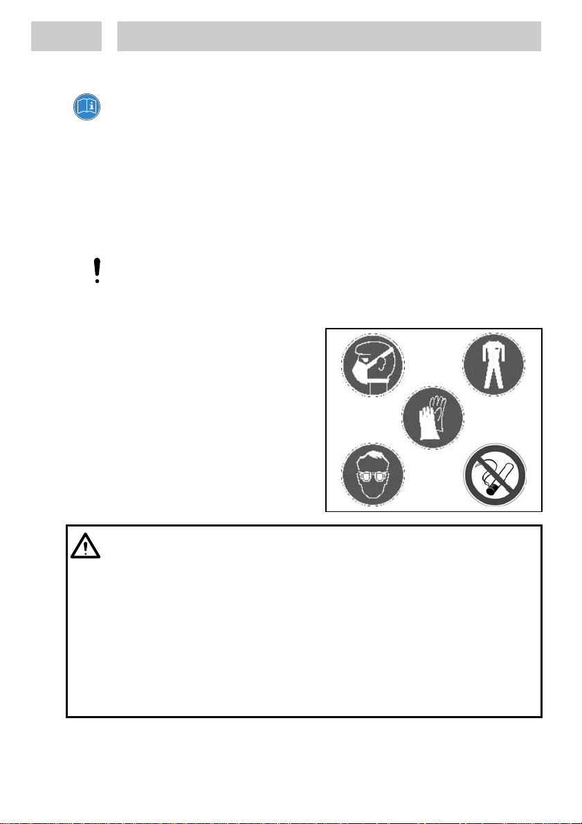
Unconditionally Instructions in Handling
1 If ventilation is insufficient, wear
suitable respiratory equipment!
2 Wear impermeable and chemical
resistant protective clothing and
apron!
3 Wear tight-fitting safety goggles!
4 Wear protection gloves!
5 Do not smoke!
1 2
3
4
5
Read and understand operator's manual before using this machine. Failure to follow
If chemical products are not properly handled, damage to health can result!
Do not use any solvents, cleaning liquids or coating materials containing 1,1,1
4
operating instructions could result in injury or damage to equipment.
Observe general safety regulations for the handling of chemicals!
Observe manufacturer’s instructions!
Trichlormethane or Methylen Chloride i.e. agents of the group of chlorinated
hydrocarbons. These chemicals may react with aluminium, anodised or zinced
parts. The chemical reaction may be explosive.
Danger caused by combustible and noxious spraying material. Safety instructions
on fluid can and material data of fluid manufacturer must definitely be observed.

1 Please observe the following
Never point the spray applicator against persons.
Spraying procedures cause noise depending on the used pressure.
If necessary, wearing of ear protection is recommended.
Keep unprotected persons away.
Avoid spilling or spraying in enclosed areas.
Use only in well-ventilated areas.
Provide adequate ventilation, also at floor level (vapors are heavier than air).
Provide processing equipment with adequate local exhaust ventilation.
Protect from heat and direct sunlight.
Do not spray on naked flames or any incandescent material.
– Keep away from sources of ignition.
Irritating to eyes, respiratory system and skin.
In case of contact with eyes, rinse immediately with plenty of water and seek
medical advice. Consult the relevant Safety Data Sheet for the product you are
using.
5
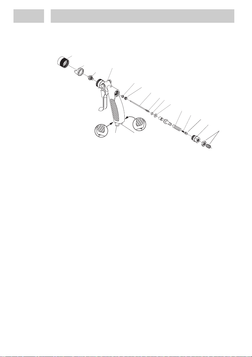
2 Description
The spray applicators 97715/97725 have been thoroughly tested before leaving
Loctite. No more adjustments are necessary prior to setting up spray operation.
1
1 Protection Ring
2 Air Cap at 97715 (90° flat fan) and 97725 (HVLP 60° flat fan).
3 Nozzle, standard is a 0.5 mm nozzle made of stainless steel.
4 Spray applicator body with trigger lever, pressurized air and agent
5 Needle Gask et (PTFE).
6 Stuffing Box
7 Needle, stainless steel.
8 Needle Nut s, M2.
9 O Ring 4.7 * 1.42 mm.
10 Valve Gasket
11 Valve Spring
12 Needle Spring
13 Val ve Lock
14 Locking Screw
15 Needle Reg ulator with Counter Nut
16 Pressurized Air Fitting “AIR” for tube, blue, OD 6 mm, ID 4 mm.
17 Agent Fitting “M” for tube, clear, OD 6 mm, ID 4 mm.
connections.
2
4
3
5
6
7
8
9
10
11
12
M
AIR
M
13
14
15
1617
6

3 Technical Data
Quality: If the required quality
is not achieved, install a
LOCTITE separator.
Filtered 10 µm, oil-free, non-condensing.
Accessory Order No. 97714
Max. Air Pressure 6 bar (87 PSI)
Max. Agent Pressure 1.5 bar (29 PSI),
see operating manual pressure pot.
Air Consumption App. 90 l/min at 3 bar (43 PSI) and 0.5 mm
nozzle
Weight 0.240 kg
Length Duo Tube ~ 3 m (~10 ft)
4 Setup and Operation
Pay attention to the safety instructions in section 1.4 “For your Safety”.
4.1 Setup
If fluid output requires to be regulated individually, apply needle regulator with
counter nut 15 for quantity of fluid flow. To spray with a spray applicator a definite
volume of atomizing air and a definite pressure of materials is needed. Activating
the trigger will open the needle and the material flows out of from the nozzle. The air
pressure atomizes the material and forms it to a jet.
The needle function is: Opening by trigger and closing by spring force.
• Connect duo tube to pressure pot or other means of feeding fluid and to main air
supply.
Clear tube: for agents, connection M 17.
Blue tube: for air pressure, connection AIR 16.
• Set air pressure to required spray droplet size by the regulator for pressurized air
at the pressure pot, see operating manual pressure pot.
• Set agent pressure to required material outlet and spray droplet size by the
regulator for agents at the pressure pot, see operating manual pressure pot.
7

4 Set Up and Operation
4.2 Operation
Fluid output can be regulated individually. Apply needle regulator with counter
nut 15 for quantity of fluid flow.
Turning needle regulator right: less fluid flow.
Turning needle regulator left: more fluid flow.
• Pull trigger at the valve body 4. Spray operation starts.
You will notice that you receive so called “pre-air” prior to opening fluid flow when
pulling the trigger. When releasing trigger you still have “purging-air” after needle
has closed, nozzle and fluid flow Has stopped. This prevents that the fluid forms
drops instead of the desired atomization.
4.3 Shutdown
• Hold up the finespray applicator.
• Depressurize the pressure pot.
The mold release agent flows back into the pressure pot.
4.4 Return to Operation
• Pressurize the pressure pot.
• Pull trigger at the valve body 4. Spray operation starts.
The feedline will be filled.
8
 Loading...