

Henkel 97612 User Manual
Operating Manual
Bedienungsanleitung
Air Filtertrolley
Luftfiltertrolley
97612
2

English...................................................................................................................... 4-14
Deutsch .................................................................................................................. 15-26
2

Contents
1 Please observe the following......................................................................................4
1.1 Emphasized Sections....................................................................................................4
1.2 Items Supplied...............................................................................................................4
1.3 For Your Safety.............................................................................................................. 5
1.4 Field of Application (Intended Usage)............................................................................ 5
2 Description...................................................................................................................6
2.1 Theory of Operation.......................................................................................................6
2.2 Displays, Operating Elements and Connections............................................................7
3 Technical Data ............................................................................................................. 8
4 Installation....................................................................................................................9
4.1 Environmental and Operating Conditions...................................................................... 9
4.2 Connecting the Unit.......................................................................................................9
4.3 Connecting the Suction Hose ........................................................................................9
4.4 Connecting the Suction Arm........................................................................................ 10
5 Operation....................................................................................................................11
6 Cleaning and Maintenance........................................................................................11
6.1 General Instructions..................................................................................................... 11
6.2 Changing the Filter ...................................................................................................... 11
7 Troubleshooting ........................................................................................................12
8 Annex..........................................................................................................................13
8.1 Accessories and Spare Parts ...................................................................................... 13
8.2 Declaration of EC Conformity ......................................................................................13
8.3 Warranty (excluding Germany).................................................................................... 14
3

1 Please observe the following
For safe and successful operation of the unit, read these instructions completely. If the
instructions are not observed, the manufacturer can assume no responsibility.
Be sure to retain this manual for future reference.
Refer to the technical data sheet for the LOCTITE-product used at www.loctite.com
contact your local technical department.
or
1.1 Emphasized Sections
Warning!
Refers to safety regulations and requires safety measures that protect the operator or
other persons from injury or danger to life.
Caution!
Emphasizes what must be done or avoided so that the unit or other property is not
damaged.
The numbers printed in bold in the text refer to the corresponding position numbers in
Notice
Gives recommendations for better handling of the unit during operation or adjustment as
well as for service activities.
the illustration on page 7.
• The point emphasizes an instruction step.
Instruction steps in the illustrations are
indicated with arrows.
When several instruction steps are
indicated in an illustration, the shading of
the arrow has the following meaning:
Black arrow = 1
Grey arrow = 2
White arrow = 3
1.2 Items Supplied
1 Filtertrolley
1 Power Cord
1 Operating Manual
As a result of technical development, the illustrations and descriptions in this operating
manual can deviate from the actual unit delivered.
st
step
nd
step
rd
step
4

1 Please observe the following
1.3 For Your Safety
Damage to the power cord or the housing can result in contact with live electrical
parts.
Check the power cord and the unit before each use.
If the power cord or the unit is damaged, do not operate!
Replace a damaged power cord with a new one.
Do not remove, by-pass or disable any safety device! It can result in damage to
the unit and is therefore prohibited!
Never use the Filtertrolley without the filter!
Unplug the Filtertrolley after use, before cleaning, maintaining and before every
repair and replacement of parts.
Neither use the Filtertrolley for vacuum cleaning nor for exhausting of liquid
media or flammable substances!
The Filtertrolley must not be used for the suction of gasses, steams and dusts in
explosive concentrations!
Always carry out disposal of worn out filter according to valid regulations for
waste!
If liquids or flammable substances are inadvertently exhausted by this device,
instantly switch off the machine.
Switch off and unplug the device at any break.
Instantly switch off the device in case of danger.
Use only original substitute and spare parts.
Filtered air must not be led back to workplaces if the unit is used for filtering
carcinogenic substances.
1.4 Field of Application (Intended Usage)
The Filtertrolley is an essential device for health and the environment protection at
bonding workplaces.
It is a robust device for the mobile and stationary workshop and industrial use. It is
suitable for exhausting and filtering gases, vapors and malodors in the workplaces.
Released, partly unhealthy gases and vapors, are captured by suction elements
immediately at the place of their origin and thereafter filtered with the Filtertrolley.
The clean air can be supplied back to the working premises.
Not valid for carcinogenic substances!
The Air Filtertrolley can be equipped via a Y splitter with two suction hoses for supplying
two workplaces.
The producer is not liable for any resulting damage arising from use outside the
intended use, the scope or these instructions.
5
2 Description
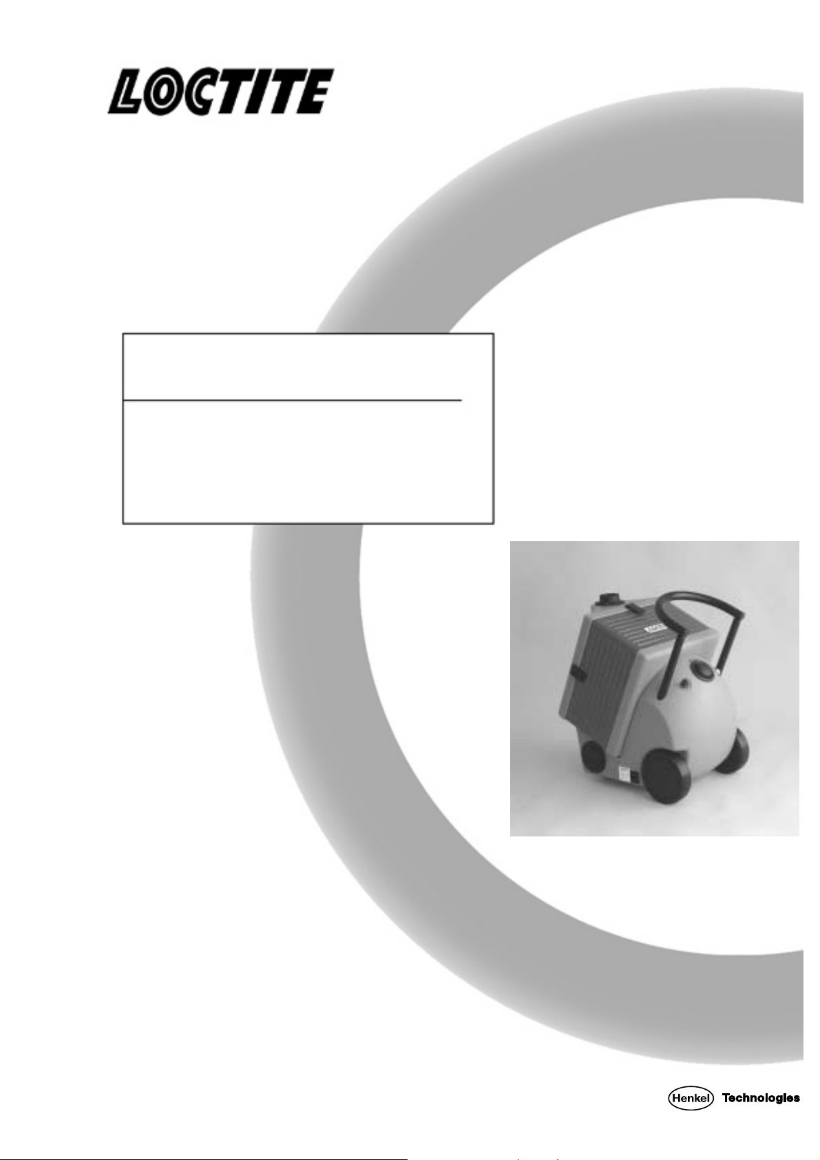
2.1 Theory of Operation
The suction hose or the suction arm (both accessories) has to be placed near the
bonding place. The unit exhausts the polluted air and blows out the cleaned air at the air
outlet.
The combination of pre-filter and activated carbon guarantees a high filtration efficiency
of unhealthy gases, vapor and fumes. The large surface area and small particle size of
the actuated carbon maximizes absorption of polluted air.
Whenever adhesive vapors are involved, life expectancy can only be estimated, as the
amount of product vapors released depends on temperature, the exposed surface area
and the length of time.
Additional contaminant loads in the air being filtered may include oil mist, cigarette
smoke, etc.
For activators and primers, calculation of service life is easy: The filter will be saturated
after extracting vapors from approx. 2.5 to 3.5 liters of solvent. However, this does not
apply for heptane, which the filter will not adsorb.
Never spray directly into the extraction tube. Minimum spray distance is 50 cm.
Risk of explosion due to super saturation!
The unit can be used for all Loctite Cleaners. Estimating when the filter will be loaded is
easy. The filter will be loaded after extracting about 2 kg of solvents. This is equivalent to
approximately 6 spray cans. Combinations of adhesives with heptane based activators
and primers - e.g. 770, 7455, 7457, etc. are an exception. In this case life expectancy is
not expected to be reduced, as heptane loading on the filter is negligible.
6
2 Description
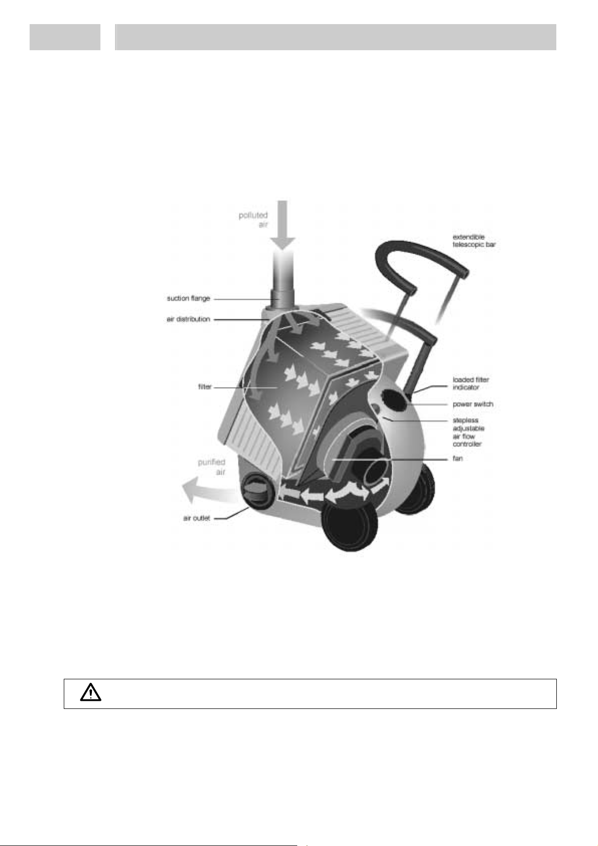
2.2 Displays, Operating Elements and Connections
12, 13
11
10
Extendible Telescopic Bar
1
Filter Indicator for clogged filter (LED
2
two-colored)
3 Power Switch 10
Stepless Adjustable Air Flow
4
Controller
5
Fan
Power Connection with Fuse 5 A,
6
time-lag
9
8
1
2
3
4
7
5
6
7
Air Outlet
8
Snap Lock
9
Filter
Air Distribution Plate
11
12
13
Suction Flange
Suction Hose
The Suction Arm (not shown).
12 and 13 are accessories.
They have to be ordered
separately.
Do not remove, by-pass or disable any safety device! It can result in damage to the unit
and is therefore prohibited!
Filter 9
Pre-Filter Mat G2
Filter Foam
Special Activated Carbon
Filter Foam
After-Filter Mat G2
7
3 Technical Data
Power Supply 230 V AC, 50 Hz
Power Consumption 150 W
Power Protection 5 A, time-lag
Protection Class I acc. to EN 60 335
Max. Air Flow 170 m³/h
Constant Air Flow 80 m³/h at 1,400 Pa
Max. Vacuum 2,800 Pa
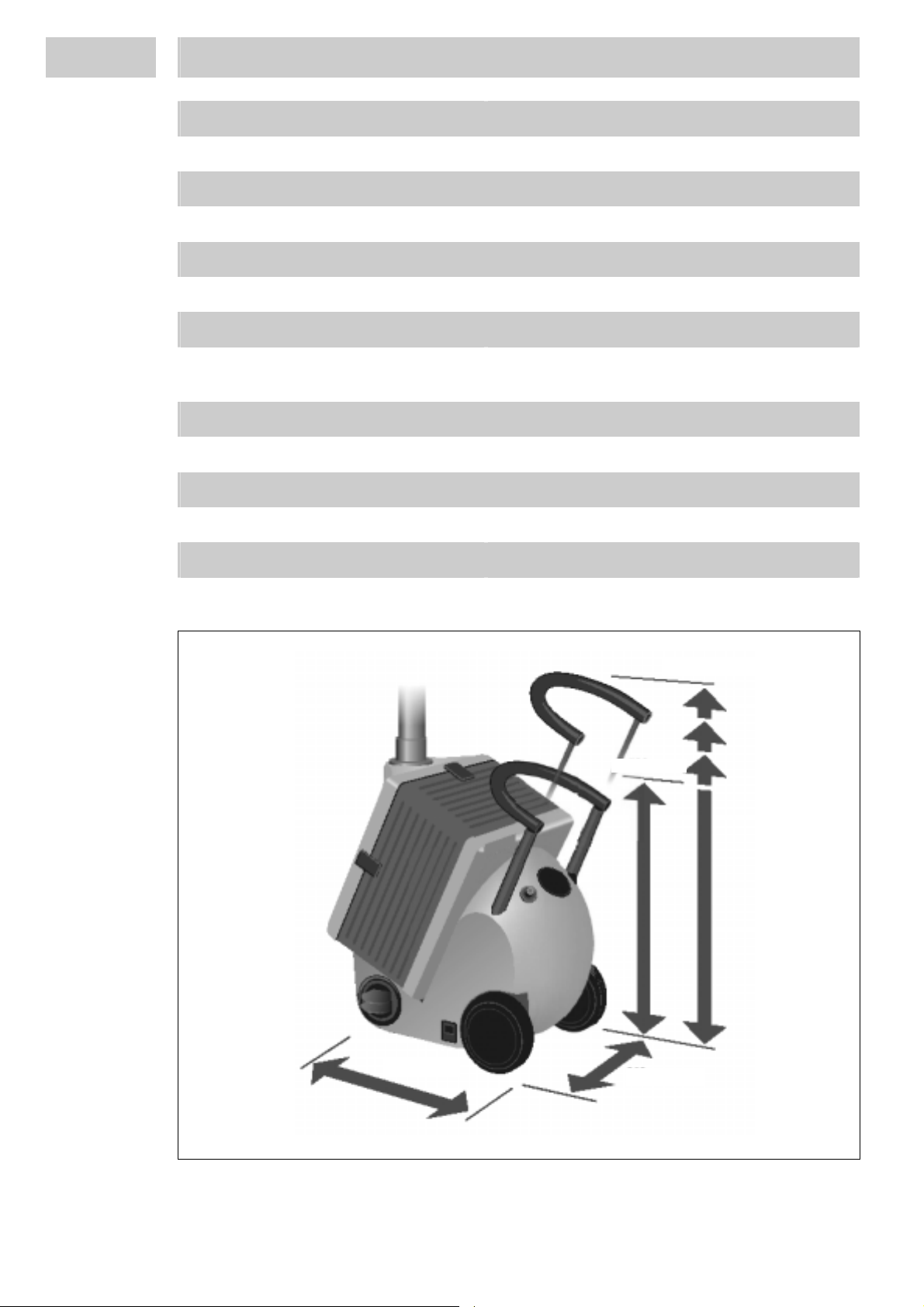
Dimensions (width x height x depth): 450 mm * 530 – ~860 mm * 340 mm
17.7” * 20.9 – ~34” * 13.4”
Ambient Operating Temperature +10°C to +45°C (50°F to 113°F)
Storage Temperature +5°C to +55°C (41°F to 131°F)
Relative Humidity for Storage Max. 50 %
Weight ~ 18 kg
Noise Level 49 dB (A)
Dimensions
Max. 860 mm
450 mm
8
340 mm
4 Installation
4.1 Environmental and Operating Conditions
– Do not operate if there is a danger of condensing humidity or condensation.
– Do not splash with water!
4.2 Connecting the Unit
• Connect power cord to the unit.
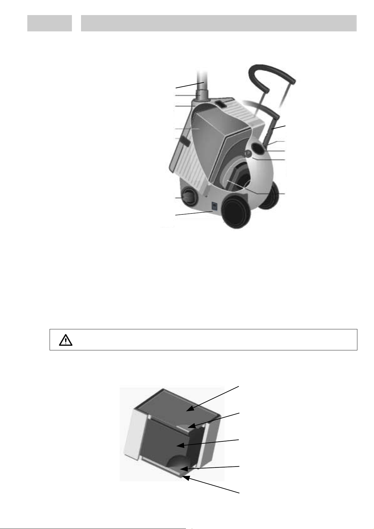
4.3 Connecting the Suction Hose
The Air Filtertrolley can be equipped via a Y splitter with two suction hoses for supplying
two workplaces. This y splitter has to be mounted before the suction hose is mounted.
The Y splitter has to be ordered separately.
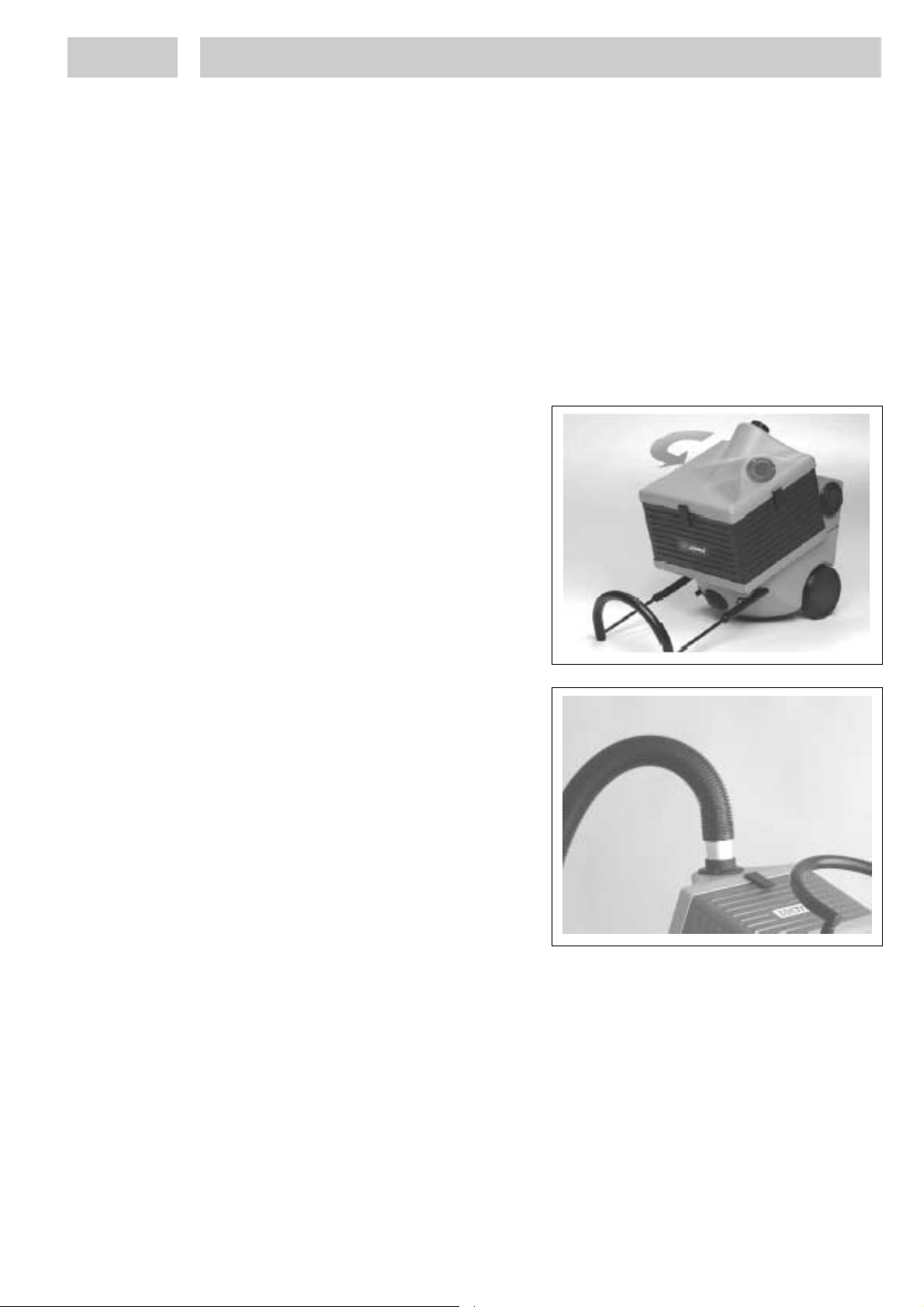
•
Open the 3 snap locks.
• Mount the air distribution plate in the
same direction as the suction flange
should be pointing.
•
Close the 3 snap locks.
• Push the suction hose into the
connecting piece.
9
 Loading...