

Henkel 9000 User Manual
EQUIPMENT
OPERATION MANUAL
Loctite
®
Series 9000
Rotospray Pump
983330

1
Table of Contents
List of Figures
Page No.
1 Warnings & Precautions . . . . . . . . . . . . . . . . . . . . . . . . . . .2
2 Introduction . . . . . . . . . . . . . . . . . . . . . . . . . . . . . . . . . . . . .3
Items Supplied . . . . . . . . . . . . . . . . . . . . . . . . . . . . . . . . . . .3
3 Installation Instructions and Required Controls . . . . . . . .4
View of Rotospray Pump with Components Labeled . . . . . . .5
4 Theory of Operation . . . . . . . . . . . . . . . . . . . . . . . . . . . . . .6
5 Operation
Priming the Pump . . . . . . . . . . . . . . . . . . . . . . . . . . . . . . . . .7
Adjusting Pump Dispense Volume . . . . . . . . . . . . . . . . . . . . .7
6 Maintenance . . . . . . . . . . . . . . . . . . . . . . . . . . . . . . . . . . . .8
Pump Replacement Procedure . . . . . . . . . . . . . . . . . . . . . . .9
7 Troubleshooting
General . . . . . . . . . . . . . . . . . . . . . . . . . . . . . . . . . . . . . . . .10
8 Replacement Parts and Assemblies . . . . . . . . . . . . . . . . .11
Phone Numbers for Help . . . . . . . . . . . . . . . . . . . . . . . . . . . 11
9 Information on Pump Rebuilding Program . . . . . . . . . . . .12
10 Specifications
Dimensions . . . . . . . . . . . . . . . . . . . . . . . . . . . . . . . . . . . . .13
Utilities Required . . . . . . . . . . . . . . . . . . . . . . . . . . . . . . . . .14
Weights . . . . . . . . . . . . . . . . . . . . . . . . . . . . . . . . . . . . . . . . 14
Pressure Ratio of Pump . . . . . . . . . . . . . . . . . . . . . . . . . . .14
11 Warranty . . . . . . . . . . . . . . . . . . . . . . . . . . . . . . . . . . . . . .15
Figure Description Page
1 View of Rotospray Pump with Components Labeled 5
2 Rotospray Pump Operating Sequence 6
3 Adjusting the Amount Dispensed 7
4 Dimensions 13

2
• OBSERVE ALL WARNINGS. READ and UNDERSTAND all instructions in the manual before
attempting to install and operate this equipment.
• This equipment has been designed and tested for use with Loctite®anaerobic products.
• DO NOT USE equipment for other than intended use.
• BE SURE that all adhesives, solvents, or fluids used are chemically compatible with the wetted
parts of the equipment.
• ALWAYS READ the Material Safety Data Sheet(s) before using adhesives, solvents, or any
other chemicals in this equipment. COMPLY with ALL WARNINGS and SAFETY
INSTRUCTIONS AS STATED.
• ALWAYS WEAR protective eye wear, gloves, clothing, and respirator as recommended in this
manual or the Material Safety Data Sheet(s).
• Any misuse of the equipment or accessories, such as over-pressurizing, modifying parts, using
incompatible chemicals, adhesives, or worn, damaged or not recommended parts, can cause
rupture or breakage and result in fluid injection, splashing in the eyes or on the skin, or other
serious injury or property damage.
• NEVER alter or modify any part of this equipment. Doing so will void the warranty and could
result in a malfunction.
• CHECK the equipment regularly and repair or replace worn or damaged parts immediately.
• NEVER exceed the recommended working pressure or the maximum air inlet pressure stated
on the equipment or in the manual.
• Properly ground all electrical components as recommended in the manual or technical data.
• Always KEEP HANDS and FINGERS away from moving parts to reduce the risk of injury.
• ALWAYS RELIEVE any pressure and turn off all power sources when checking or servicing
any part of the equipment to reduce the risk of serious injury.
• RETAIN THIS MANUAL FOR FUTURE REFERENCE.
Warnings and Precautions1

3
Introduction2
The Loctite®Series 9000 Rotospray Pump will apply a metered amount of Loctite
®
anaerobic products to a Rotospray centrifugal force dispensing head.
The Loctite Series 9000 Rotospray Pump is pneumatically operated and needs a 4-way
pneumatic valve to control the pneumatic signals.
The Loctite Series 9000 Rotospray Pump is usually part of a system that consists of the
following components:
1. Agravity reservoir to supply product to the Loctite Rotospray Pump.
2. The Loctite Rotospray Pump itself.
3. ARotospray centrifugal force dispense head.
4. Aproduct tube between the pump and dispense head.
5. An electro-pneumatic or pneumatic control system.
This manual will cover the Loctite Series 9000 Rotospray Pump part number 983330 only.
The Loctite Series 9000 Rotospray Pump is designed to pump anaerobic materials with
viscosity <100,000cps that can be gravity fed to the pump. The pump displacement range is
0.02 cc to 0.40 cc.
Typical Loctite®Products are:
Loctite product 271™, 277, 620, 635, 640, 11264, 11358, 11747, and 12019.
The Loctite Rotospray Pump is not suitable for dispensing moisture cure products such
as RTV Silicones or Cyanoacrylates.
Because The Loctite Rotospray Pump is pneumatic, the only utility needed is compressed air.
See the specifications on page 14 for the air quality requirements.
Because anaerobic products are being dispensed, the parts which come in contact with
the Loctite Anaerobic products are made as inert as possible. This helps prevent product
curing within the system. In addition, the pump is designed with a minimum of dead
areas or close clearances where anaerobic curing can start.
Items Supplied:
993330 Loctite Series 9000 Rotospray Pump includes:
Packaging and Inserts.
(1) Loctite Rotospray Pump consisting of a pump section and an actuator section.
(1) Mounting Bracket (983335).
(1) Feedline Accessory Kit (983356).
(1) Air Line Kit (983482).
(1) Instruction Manual (983355).
Note:
See the Spare Parts List on page 11 for available spare parts.

4
Installation3
Inspection Before Installation
The Loctite Rotospray Pump was inspected before shipment. Check the items in the shipping
container against the list on Page 3 of this Manual. After removing the items from the shipping
container inspect them for visible damage. Promptly report any damaged or missing parts to
both the shipper and your Loctite representative.
CAUTION: DO NOT REMOVE ANY ITEMS THAT ARE SEALED IN PLASTIC BAGS UNTIL
THEY ARE TO BE USED AS THEY MAY BECOME CONTAMINATED RESULTING IN
PERFORMANCE PROBLEMS.
Installation
Locate the pump so that:
1. The pump axis is horizontal.
2. The pump is at least 12 inches (300 mm) below the outlet of the gravity feed reservoir.
3. The pump is at approximately 4 inches (100 mm) below the centerline of the Rotospray
centrifugal force dispensing head.
4. There is enough clearance to allow easy access to the outlet fitting.
5. There is enough clearance to allow easy access to the control air fittings.
6. The Rotospray centrifugal force dispensing head is within the range of the outlet tubing.
Install the pump assembly into the Mounting Bracket (Part no. 983335).
Secure the Bracket to the mounting surface with suitable fasteners.
See Fig. 4 on page 13 for the bracket mounting hole dimensions and overall pump dimensions.
Other Controls
1. The pump requires a 4-way pneumatic valve to operate. The valve should have a Cv of 0.5
and 1/8 NPT ports.
2. The pneumatic valve shall have both Manual and Automatic modes of operation.
3. Atiming device will be required to operate 4-way valve that controls the pump.
Connecting Air and Product Lines
1. Install the air line fittings into the 1/8 NPT ports in the pneumatic actuator.
2. Connect the normally not passing control valve port to the actuator port closest to the
adjustment knob, (“Dispense” port on actuator).
3. Connect the normally passing control valve port to the actuator port farthest from the
adjustment knob, (“Retract” port on actuator).
4. Connect 3/8-inch OD tubing from the product reservoir to the pump inlet.
5. Connect 1/4-inch OD tubing from the pump outlet to the applicator being used.
Installation, cont.4
5
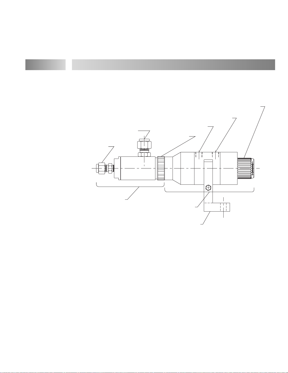
Fig. 1
View of the Pump with Component Labeled.
PUMP ASSEMBLY (983117)
PRODUCT
OUTLET
FITTING
CONTROL AIR "DISPENSE" PORT
ACTUATOR ASSEMBLY (983116)
CONTROL AIR "RETRACT" PORT
PRODUCT
INLET
FITTING
LOCKING RING
STROKE ADJUSTER KNOB
MOUNTING BRACKET (983335)
 Loading...