

Page 1
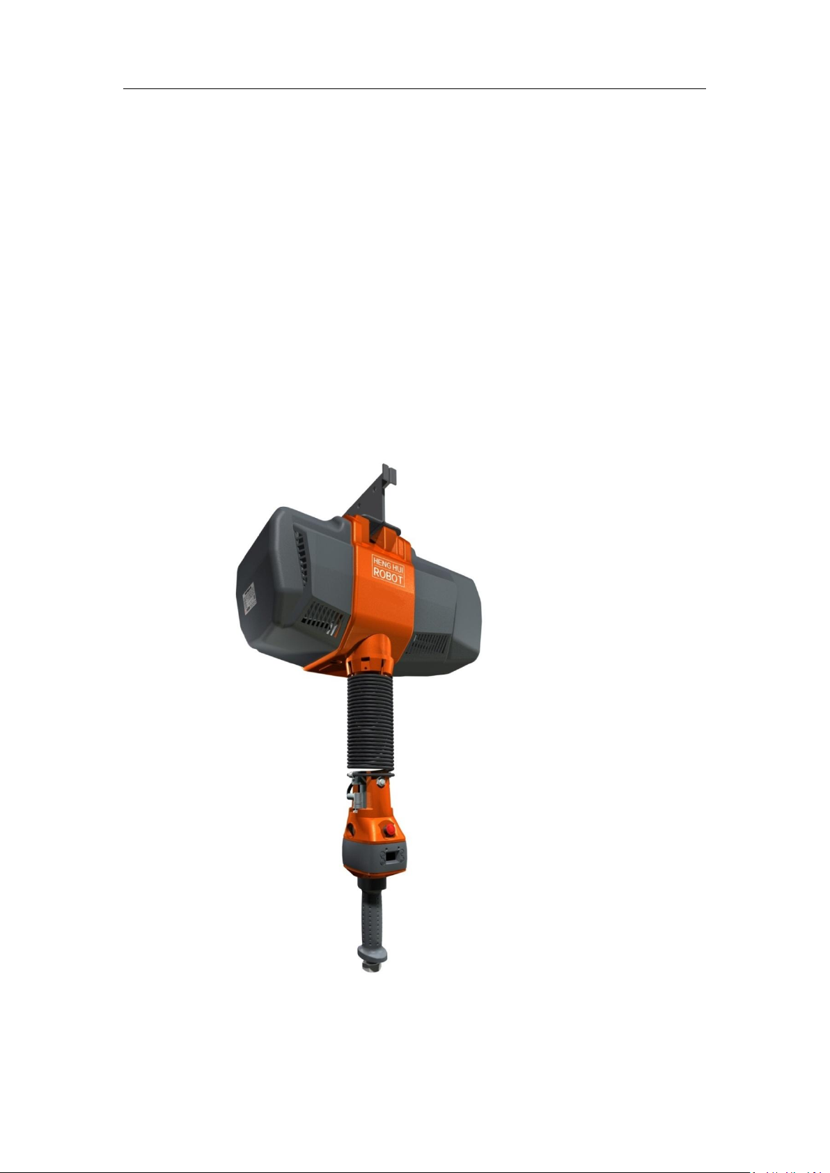
Intelligence Aided
Lifting Equipment
User Manual
(V4.71)
November 2018
Page 2

Intelligence Aided Lifting Equipment
Preface
Thank you for choosing our product! This User Manual provides information in respect of the
intelligence aided lifting equipment covering the following:
Safety
Product overview
Start-up
Function description
Extended Function
Menu setting
Maintenance & service
Revision:
Adjustment on dual suspension. (Version V8024 or above required)
Additional functions of no-load deceleration, separate reset of soft limit, etc. (Version V8025 or
above required)
Additional control modes for fall prevention function, etc. (Version V8026 or above required)
Newly-added display on handle side of servo driver alarm codes. (Version V8027 or above
required)
Newly-added function for separate definition of soft limit under Grip and Suspension modes.
(Version V8028 or above required)
Newly-added instructions of all-touch handle and coaxial pressure handle.
Tips
If this is the first time you use this product, please carefully read this User Manual. For any doubt
with regard to functions or performance, please don’t hesitate to contact our technicians for
assistance.
Please make this User Manual readily accessible for reference at any time.
Shaoxing Henghui Robot Technology Co., Ltd. reserves all rights of this User Manual. In no case
should, without our written authorization, any technical specification, drawing or diagram be
wholly or partially copied, distributed, used for competition or provided to any third party.
We are committed to continuous improvement on intelligence aided lifting equipment, hence
changes may occur to any information provided by us without prior notice, and we appreciate your
understanding.
2
Page 3

Intelligence Aided Lifting Equipment
Table of Contents
Chapter I Safety ........................................................................................................................ 6
1.1 Safety precautions ..................................................................................................... 6
1.2 Safety signs ............................................................................................................... 8
1.3 Safety protection device ............................................................................................ 9
1.3.1 Limit switch ...................................................................................................... 9
1.3.2 Steel cable locking device ................................................................................. 9
1.3.3 Overload prevention device ............................................................................ 10
1.3.4 Forced cooler ................................................................................................... 10
1.3.5 Emergency stop button .................................................................................... 11
Chapter II Overview ................................................................................................................. 12
2.1 Introduction ............................................................................................................. 12
2.2 Major application and scope ................................................................................... 12
2.3 Main components and functions ............................................................................. 12
2.4 Types of handles ...................................................................................................... 13
2.5 Signal connection line ............................................................................................. 14
2.5.1 Wire map of signal connection line ................................................................. 14
2.6 H360 Sliding Circle ................................................................................................. 15
2.7 Composition and meanings of model ...................................................................... 16
2.8 Nameplate ............................................................................................................... 16
2.9 Basic operation interface ......................................................................................... 17
2.10 Main technical parameters ...................................................................................... 18
2.11 Basic dimensions ..................................................................................................... 19
2.12 Main components .................................................................................................... 20
Chapter III Start ......................................................................................................................... 21
3.1 Power supply ........................................................................................................... 21
3.2 Connection of transformer ...................................................................................... 22
3.3 Description of signal cable pins of the host ............................................................ 23
3.4 Initial start ............................................................................................................... 23
Chapter IV Basic function.......................................................................................................... 25
4.1 Mode of manual hold .............................................................................................. 25
4.1.1 Operation mode ............................................................................................... 25
4.1.2 Infrared sensor ................................................................................................. 25
3
Page 4

Intelligence Aided Lifting Equipment
4.1.3 Adjust the maximum operating speed in mode of manual hold ...................... 25
4.1.4 No-load deceleration function ......................................................................... 26
4.2 Suspension mode ..................................................................................................... 27
4.2.1 Operation mode ............................................................................................... 27
4.2.2 Notes to suspension mode ............................................................................... 27
4.3 Levitation unloading mode...................................................................................... 28
4.3.1 Operation steps ................................................................................................ 28
4.3.2 Suspension unloading mode description ......................................................... 28
4.4 Automatic suspension function ............................................................................... 28
4.4.1 Operation steps ................................................................................................ 29
4.5 Unloading function .................................................................................................. 29
4.5.1 Operation Method ........................................................................................... 29
4.6 Soft limit ................................................................................................................. 30
4.6.1 Operation steps ................................................................................................ 30
4.6.2 Precautions ...................................................................................................... 30
4.7 Inching button operation ......................................................................................... 31
4.8 Function switch ....................................................................................................... 32
Chapter V Extended Function .................................................................................................. 34
5.1 Inching function ...................................................................................................... 34
5.1.1 Usage mode ..................................................................................................... 34
5.1.2 Fast gear and slow gear speed adjustment ....................................................... 35
5.2 Switching of modes ................................................................................................. 35
5.2.1 Usage mode ..................................................................................................... 35
5.3 Double limit function .............................................................................................. 36
5.3.1 Usage Method ................................................................................................. 36
5.4 Double suspension function .................................................................................... 37
5.4.1 Double suspension weight setting ................................................................... 37
5.4.2 Double suspension mode setting ..................................................................... 37
5.4.3 Signal selection ............................................................................................... 38
5.4.4 Protection settings for dual suspension ........................................................... 40
5.5 Anti-drop function ................................................................................................... 40
5.5.1 Anti-drop threshold setting .............................................................................. 41
5.5.2 Signal setting ................................................................................................... 41
5.5.3 Clamping protection function .......................................................................... 41
5.6 Auto homing function ............................................................................................. 43
4
Page 5

Intelligence Aided Lifting Equipment
5.6.1 Homing Weight Setting ................................................................................... 43
5.6.2 Usage method .................................................................................................. 43
5.7 Palletizing function ................................................................................................. 43
5.7.1 Signal setting ................................................................................................... 44
5.7.2 Operation steps ................................................................................................ 44
5.8 Wireless Remote Control Module ........................................................................... 45
5.8.1 Operation methods for the wireless remote control ........................................ 45
5.9 Expansion interface ................................................................................................. 45
5.9.1 Host extension interface .................................................................................. 45
5.7.2 Handle extension interface .............................................................................. 47
5.9.3 External Expansion Board Interface ................................................................ 51
Chapter VI Menu setting ............................................................................................................ 55
6.1 Overview ................................................................................................................. 55
6.1.1 Operation mode ............................................................................................... 55
6.2 Description of menu functions ................................................................................ 56
Chapter VII Maintenance ............................................................................................................ 66
7.1 Inspection & Maintenance Timetable...................................................................... 66
7.2 Basic failure diagnosis ............................................................................................ 66
7.3 Servo driver battery replacement ............................................................................ 73
7.3.1 Operation steps ................................................................................................ 73
7.4 Calibrate the handle holder ..................................................................................... 73
Chapter VIII Annex .............................................................................................................. 75
8.1 Use of wireless remote controller and receiver ....................................................... 75
8.2 Dimensional drawing of H360 sliding circle .......................................................... 76
8.3 Dimensional drawing of indefinitely variable speeds handle .................................. 76
8.4 Extended box ........................................................................................................... 77
8.5 Remote installation sliding handle .......................................................................... 77
5
Page 6

Intelligence Aided Lifting Equipment
Chapter I Safety
1.1 Safety precautions
1. The users must be familiar with and abide by the following safety matters before the
storage, installation, operation, inspection and maintenance of the products.
2. Prompt: Non-conformance to the safety precautions may cause severe personal
injury or even death or damage to the equipment.
3. DO NOT attach any cable, air pipe or the like to steel wire sleeves or spring cables.
Such attachment may compromise the accuracy of a safety sensor and damage the
equipment.
4. Please make sure you are familiar with this User Manual before any operation.
5. Do not operate the equipment in case of any discomfort.
6. An operator must focus on the equipment during operation.
7. DO NOT lift any weight beyond the rated capability of the equipment.
8. DO NOT use any lifting hook without a latch or that is damaged.
9. This product is not designed and manufactured for man riding but for products, hence
man riding is prohibited.
10. DO NOT have anyone stay in the activity range of load lifting.
11. DO NOT prolong the lifting of any weight, otherwise the life of steel wire will be
shortened and the risk of personal injury may occur.
12. DO NOT operate any intelligence aided lifting equipment with any electrical or
mechanical flaw.
13. Please do not cut off the power supply during lifting.
14. DO NOT install any object on the sliding handle. It may become an obstruction to the
normal operation of the equipment.
15. Please do not wash the equipment or clean it with wet rag.
16. Please do not frequently switch on and off the equipment.
17. Please do not conceal or remove any sign attached to the equipment.
18. Please do not trigger the infrared sensor for long when the equipment is not in use.
19. Please do not dismantle or fix the product unless you are a professional maintenance
man.
20. DO NOT maintain the equipment if it’s electrified.
21. Please wait for no less than 10 minutes after cutting off the power prior to perform any
maintenance or service.
22. Check whether the hook and the load steel wire rope are damaged or not before use.
6
Page 7

Intelligence Aided Lifting Equipment
23. The load steel wire rope needs to be kept clean and in good condition.
24. Prior to any operation, please check the load steel wire rope for any loop, knot, twist,
bend or foreign matter.
25. A steel wire rope provided by us is needed when modifying one.
26. Please press the emergency button ONLY in case of an emergency if the equipment is
operating in a high speed.
27. Upon installation of a lifting hook, its thread must be screwed to the depth of 40 mm to
avoid risks as a result of insufficient installation depth.
28. Inching buttons are for equipment maintenance and steel cable replacement only and
shall not be used during normal operation.
29. A limit switch is to prevent lifting movement beyond the position limit and shall not be
used as a stroke limit.
30. Please do not involve a steel cable directly when it’s loose.
7
Page 8
Intelligence Aided Lifting Equipment
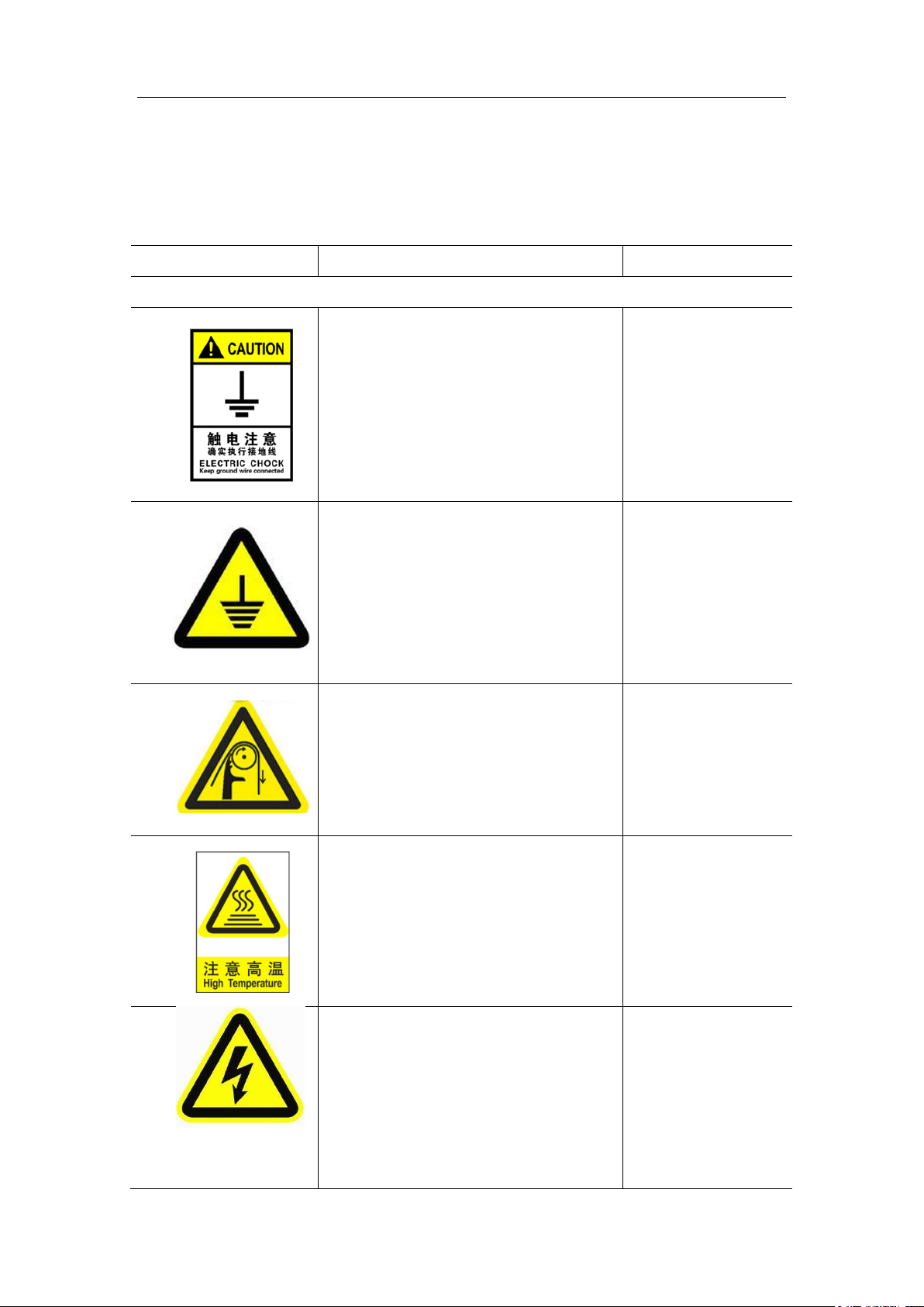
Sign
Name
Position
Warning signs
Grounding
Means the equipment must be grounded, otherwise
short circuit of equipment or personal injury may
occur. Even worse, lives may be endangered or
equipment damaged.
Transformers,
aviation connectors.
Earthing mark
Means protective earthing must be performed for
the parts on equipment, otherwise short circuit of
equipment or personal injury may occur. Even
worse, lives may be endangered or equipment
damaged.
Main unit enclosure
Entangling sign
Means an entangling risk exists in that area or
item, hence no touching is allowed. Disobeying
this rule will give rise to personal injury or even
death.
Protective jacket of
steel wire rope
Caution! Hot surface.
Means that area or item may be in high
temperature. Do not touch it. Disobeying this rule
may cause burns.
Regenerative (brake)
resistor
Beware of electric shock
Indicates that area or item may be electrified. Do
not touch it. Disobeying this rule may cause
electric shock, giving rise to short circuit of
equipment or personal injury. Even worse, lives
may be endangered or equipment damaged.
Terminals
1.2 Safety signs
A safety sign reminds operators or servicemen of potential risks, and hence it is an important
facility for identifying and avoiding danger.
8
Page 9
Intelligence Aided Lifting Equipment
1.3 Safety protection device
A safety protection device is designed to prevent accidents of intelligence aided lifting
equipment, consisting of limit switches that limit movement, steel cable locking device, overload
prevention device and forced cooling devices.
1.3.1 Limit switch
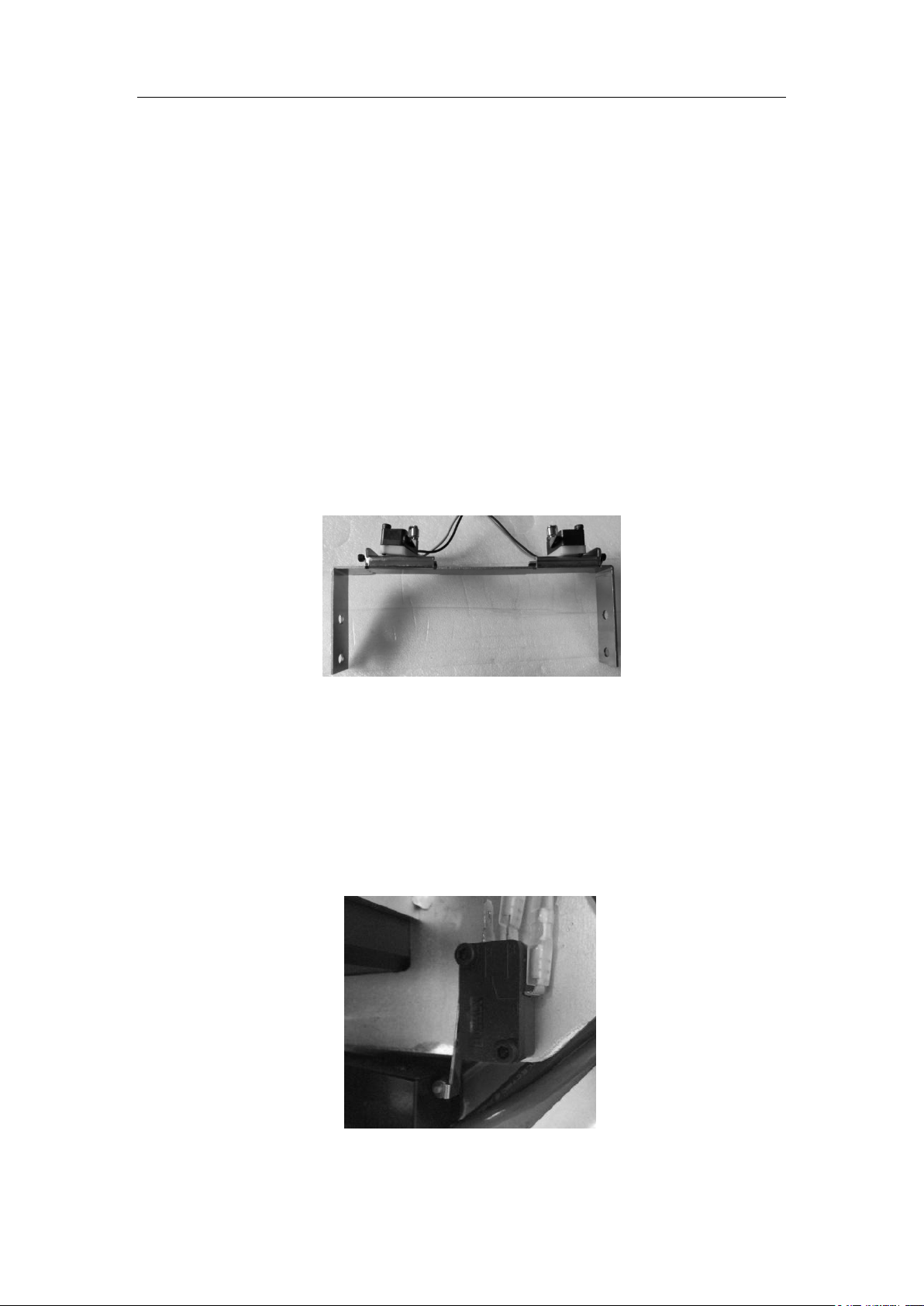
The intelligence aided lifting equipment is provided with limit switches (Fig. 1. 1) to ensure
reliable operation. A stroke limit switch comprises of an upper and a lower limit switches. When
the equipment operates upward to some 10 cm before the upper limit, it starts to decelerate to
prevent the weight from breaking away from the lifting hook. If the equipment reaches the upper
limit position, the limit switch will be triggered and the equipment can only move downward. The
lower limit switch is designed to ensure at least two turns of steel cable stay on the reel. The
equipment can move upward only if the lower limit switch is triggered.
Fig. 1. 1 Stroke limit switch
1.3.2 Steel cable locking device
The intelligence aided lifting equipment is provided with a micro switch to detect steel cable
looseness (Fig. 1. 2). When a steel cable is loose in operating equipment, the micro switch will
detect such looseness and trigger relevant actions, and then the display on the handle will indicate
“steel cable looseness alert” and the equipment can only move upward.
Fig. 1. 2 Micro switch to detect the looseness of steel cable
9
Page 10
Intelligence Aided Lifting Equipment
1.3.3 Overload prevention device
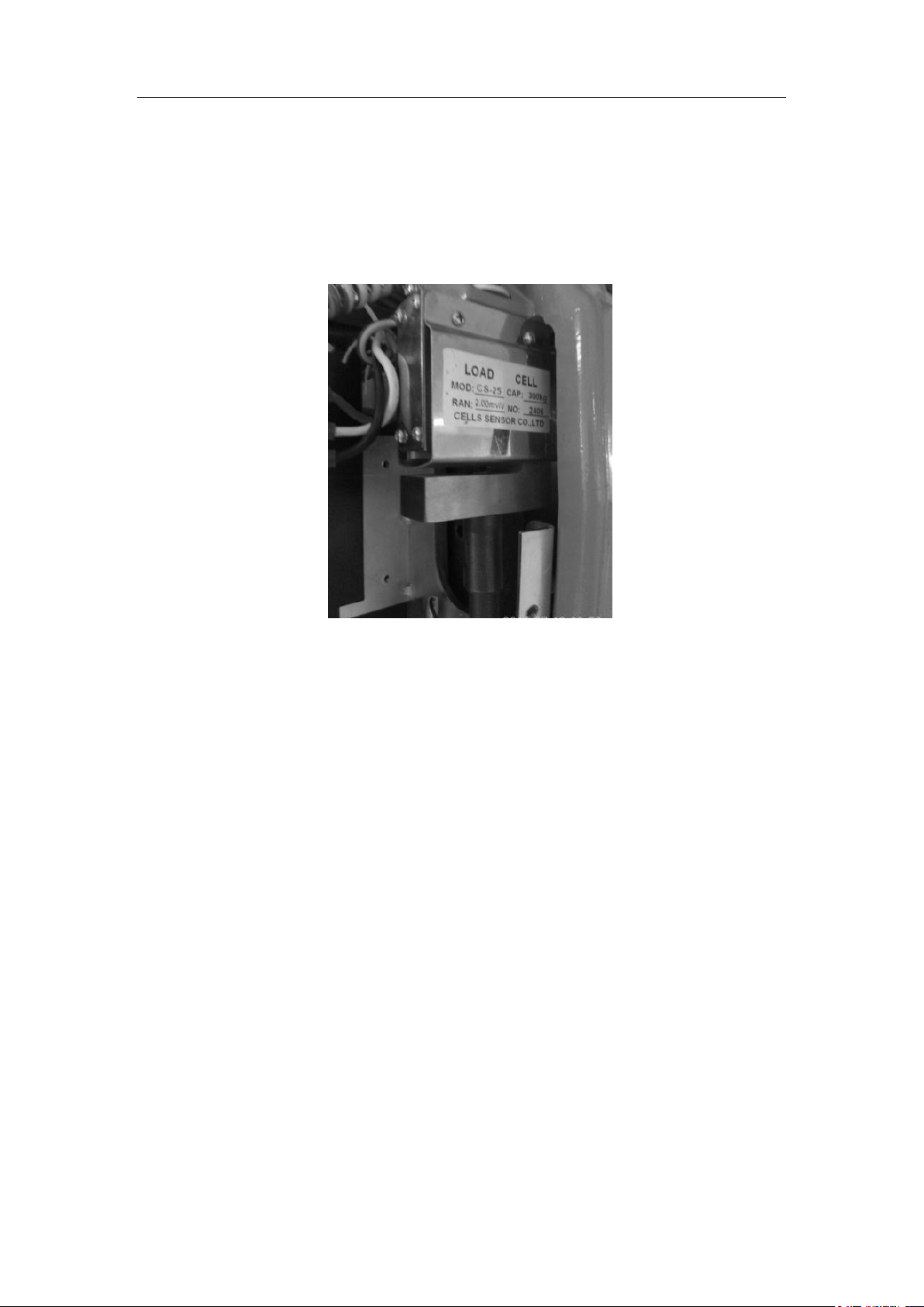
The intelligence aided lifting equipment is provided with a weighing sensor (Fig. 1. 3). When
the weight to be lifted exceeds the set value or rated bearing capacity, lifting will stop and
“Overload Alarm” be displayed on the screen, in which the equipment can move downward only
(overload weight < 150% of bearing capacity).
Fig. 1. 3 Weighing sensor
1.3.4 Forced cooler
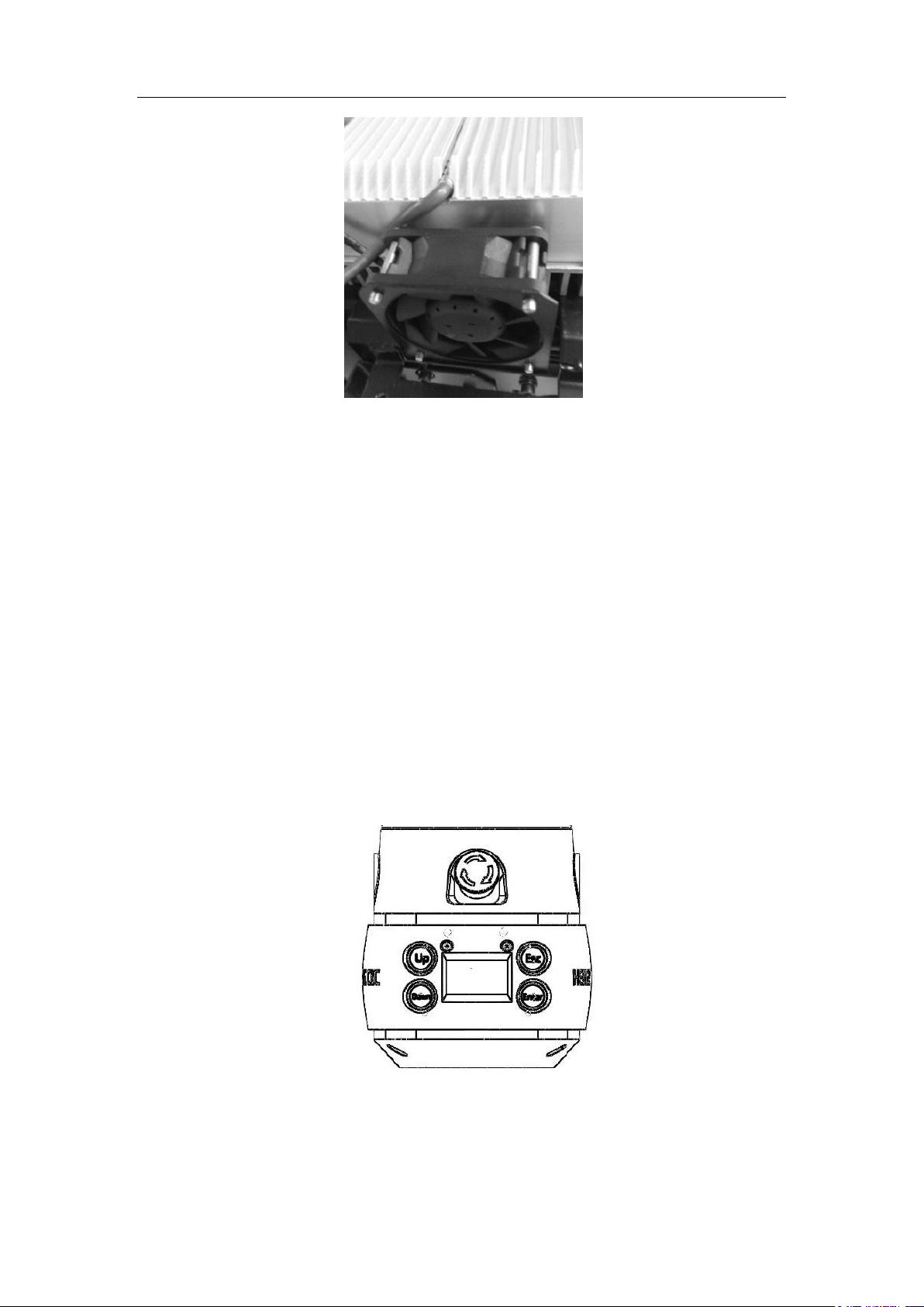
The intelligence aided lifting equipment is provided with a temperature sensor (Fig. 1. 4). It
is configured to detect the real-time temperature of braking resistor. In case that the detected
temperature is above 50 °C, the DC fan will produce forced air to cool the braking resistor. While
in the event that such temperature is above 100 °C, system operation will be suspended until the
temperature drops back to 80 °C. This device is applied only for 200 KG, 300 KG and 600 KG
types.
10
Page 11
Intelligence Aided Lifting Equipment
Fig. 1. 4 Forced cooling device
1.3.5 Emergency stop button
By pressing the emergency stop button on the handle (Fig. 1. 5), manual operation or
suspension lifting of the equipment will be disabled other than menu viewing or editing. While the
emergency stop brakes the equipment by direct control of the motor through hardware!
In case that maintenance and service, parameter setting, system upgrade and power-on
standby are performed with the equipment electrified, the emergency stop button must be kept
pressed and locked.
Note:
If the emergency stop button is pressed during equipment movement, it will be forced to stop
immediately. Therefore, please do not press the emergency stop button at will other than a true
emergency under heavy-load or fast movement, otherwise equipment damage or personal injury
may occur!
Fig. 1. 5 Emergency stop button
11
Page 12

Intelligence Aided Lifting Equipment
Chapter II Overview
2.1 Introduction
The intelligence aided lifting equipment is a material handling device that conforms to
human engineering, comprising of servo drives, servo motors, decelerators, sensors and relevant
structures and controlled by a micro-processor. It features easy operation, high precision,
intelligence, controllable speed, safety and reliability, etc.. The intelligence aided lifting
equipment produced by us includes four types by rated lifting capacity, i.e. 80KG, 200KG, 300KG
and 600KG.
2.2 Major application and scope
Automobile industry (including engines, gearboxes, new energy battery assembly, etc.)
Finish machining
Machinery manufacturing and processing
Energy industry
Handling work with high repeatability
Parts assembly
Warehouse loading and unloading
2.3 Main components and functions
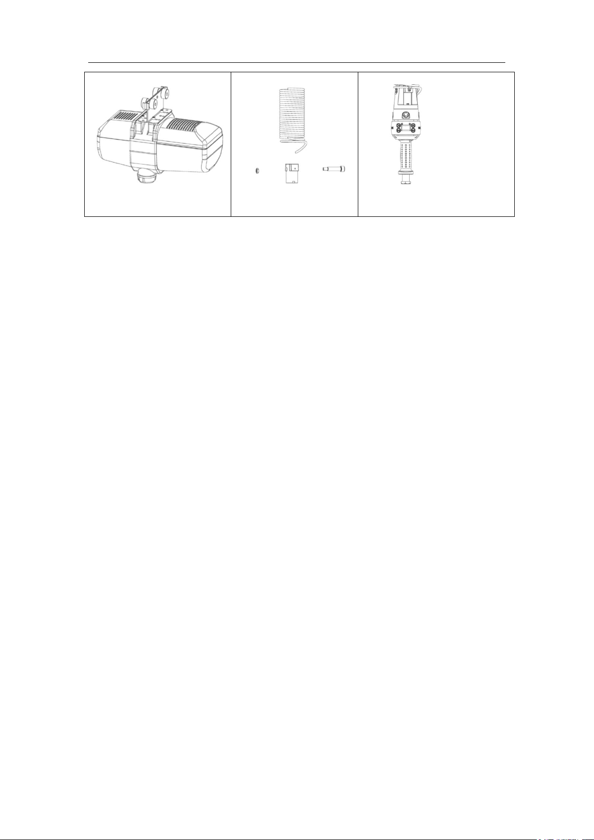
Intelligence aided lifting equipment consists of three major parts as follows1:
Main engine (Fig. 2 1): The main engine comprises mainly of a servo drive, a servo motor, a
decelerator, sensors and a main control panel. It is designed to provide power necessary for the
device to achieve accurate control and lifting, and to process signals.
Spring cable (Fig. 2 2): transmit signals between the main control and the handle, including
lifting orientation, lifting speed, emergency stop and fault signals.
Coaxial sliding handle (Fig. 2 3): consists of control panel, display, handle sliding circle,
displacement sensor and infrared sensor. A handle serves as the main interface between operators
and lifting equipment, by which users may control the lifting of equipment. Users may also
acquire the applicable information through the display.
1
A non-derivative combination
12
Page 13
Intelligence Aided Lifting Equipment
Fig. 2 1 Main unit
Fig. 2 2 Spring cable
Fig. 2 3 Coaxial sliding handle
2.4 Types of handles
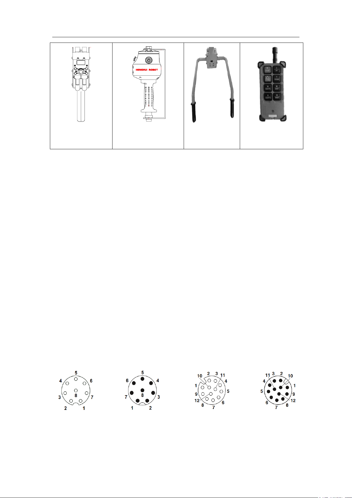
Apart from a coaxial sliding handle, the intelligence aided lifting equipment may be provided
with a CVT handle, a remote installation sliding handle, an all-touch handle, a wireless handle and
a coaxial pressure handle, depending on the varying station requirements.
CVT handle (Fig. 2. 4): applies to a workplace with limited height and inaccessible to
operators. Users can control equipment lifting through UP and DOWN and acquire corresponding
information through the display. This type of handles may be integrated into the terminal fixture or
hung vertically beneath the main engine.
Sliding handle for remote installation (Fig. 2. 5): applies to a workplace with limited height
and inaccessible to operators. This type of handles can be integrated into the fixture of or secured
externally on a terminal. Its functions resemble a coaxial sliding handle.
All-touch handle (Fig. 2. 6): provided with a built-in pressure sensor. When the force applied
on the handle varies, the equipment moves.
Wireless handle (Fig. 2. 7): allows to remotely control the main engine, applicable to a
workplace inaccessible to operators. This kind of handles provides functions of Fast Gear
Operation, Slow Gear Operation, Suspension Switch and Suspension Unloading Switch.
Coaxial pressure handle: provided with a built-in pressure sensor. When the force applied to
the rubber handle varies, the equipment moves.
13
Page 14
Intelligence Aided Lifting Equipment
Fig. 2. 4 CVT handle
Fig. 2. 5 Sliding handle for
remote installation
Fig. 2. 6 All-touch
handle
Fig. 2. 7 Wireless
handle
Hole-type, 8-core
Needle-type, 8-core
Hole-type, 12-core
Needle-type, 12-core
2.5 Signal connection line
In addition to spring wires, the straight connection wires of stepless handles (straight or spring
wires), folding extension wires, H360-handle connection wire A, and H360--handle connection
wire C, depending on different models and handles, can also be used for the connection between
the host and the handles of the intelligent lifting equipment, with the following functions:
Spring wires: connecting the host with a coaxial sliding handle or H360 sliding circle.
Straight connection wires of stepless handles: connecting the host with stepless speed-changing
handle.
Folding extension wires: generally used for the connection of the host and the spring wires
(straight connection wires of stepless handles) in a folded arm
H360-handle connection wire A: connecting H360 sliding circle and remotely installed sliding
handle.
H360-handle connection wire C: connecting H360 sliding circle and stepless speed-changing
handle or all-touch handle.
2.5.1 Wire map of signal connection line
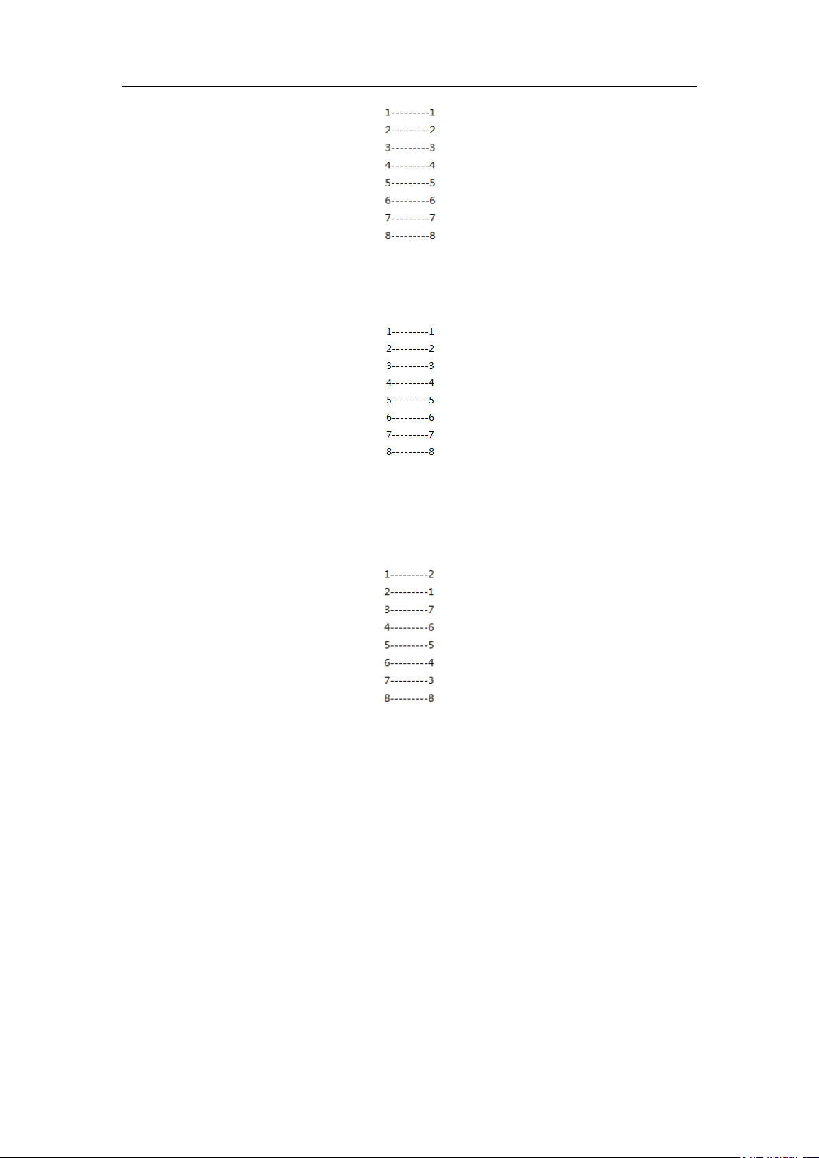
Numbering and definition of the pins for 8-core connector and 12-core connector are given in
Fig. 2.8.
straight connection wires of stepless handles is shown below:
Fig. 2. 8 Numbering and definition of pins
The wire map of pins for connectors at both ends of spring wires, folding extension wires and
14
Page 15
Intelligence Aided Lifting Equipment
Needle
Hole
Hole
Hole
Hole
Hole
The wire map of pins for connectors at both ends of H360-handle connection wire A is shown
below:
The wire map of pins for connectors at both ends of H360-handle connection wire C is shown
below:
2.6 H360 Sliding Circle
The H360 sliding circle (Fig. 1. 6) is used in combination with a remote installation sliding
handle, CVT handle or all-touch handle. Its built-in sliding circle and air tube connector
effectively eliminate the twist of signal cables and air tubes.
15
Page 16
Intelligence Aided Lifting Equipment
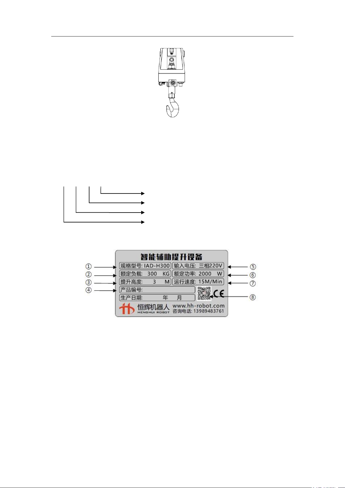
IAD-H080-500-A10
Product Version
Length of steel cable (cm):
Hoisting capacity (kg):
Product code: Intelligence Aided Lifting Equipment
Fig. 1. 6 H360 sliding circle
2.7 Composition and meanings of model
The following is the model composition and meanings of a main engine of intelligence aided
lifting equipment.
2.8 Nameplate
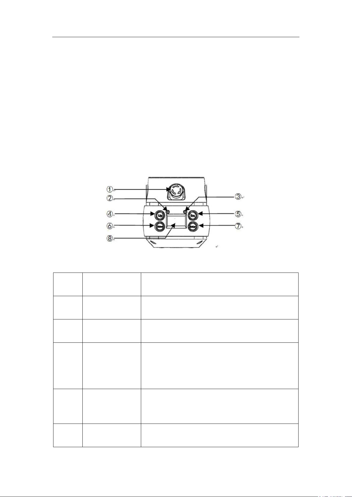
1. Type and model
The type and model of the said equipment.
2. Rated capacity
Rated lifting capacity of the equipment.
3. Lifting height
Maximum stroke of the equipment.
4. Product No.
Sequential figures indicating the production number of a product.
5. Input voltage
The power supply voltage of the said type, at 50HZ.
6. Rated power
16
Page 17
Intelligence Aided Lifting Equipment
S/N
Corresponding
function
Function description
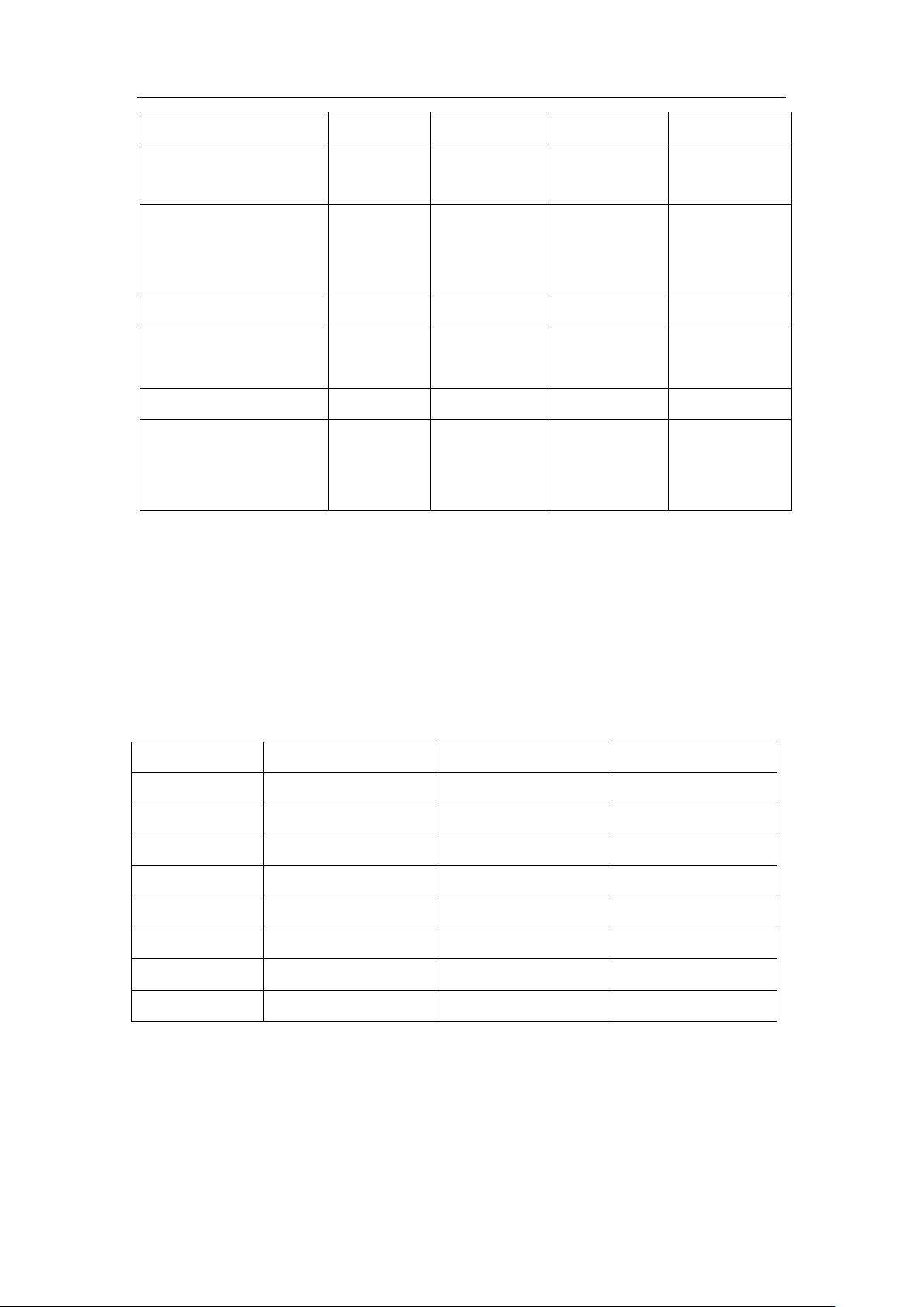
1
Emergency stop
switch
If pressed, equipment enters emergency stop mode, under
which equipment lifting will be banned;
2
Failure indicating
lamp
Off: equipment operates normally;
On: Equipment fails or is under emergency stop mode;
3
Running indicator
Blinking slowly: equipment operates normally (lock mode
and emergency stop mode);
Blinking quickly: Unloading mode;
Shining constantly: Suspension/suspension unloading mode;
4
“UP” button
Select “UP” button on the menu;
By holding it (for 2 s) under the lock mode, the equipment
enters “suspension unloading mode”;
5
“ESC” button
Return to the previous menu;
By holding it (for 2 s) under the lock mode, the equipment
The rated power of the said type.
7. Operation speed
The maximum operation speed of the equipment.
8. QR code and CE certification
Product information can be acquired by scanning the QR code. This product has passed CE certification.
2.9 Basic operation interface
The basic operation interface of intelligence aided lifting equipment (Fig. 2. 9) comprises of
an emergency stop button, “UP” button, “DOWN” button, “ESC” button, “ENT” button, LCD
display and status indication lamps. Users may carry out operations on the system through
external buttons and acquire corresponding information through the LCD display. Refer to Table 1
for details.
Table 1
Fig. 2. 9 Basic operation interface
17
Page 18

Intelligence Aided Lifting Equipment
enters “suspension mode”;
6
“DOWN” button
Select “DOWN” button on the menu;
By holding it (for 2 s) under the lock mode, the equipment
enters “unloading mode”;
7
“ENT” button
Enter the next menu;
Execute the saving operation;
8
LCD screen
Displays operation modes, relative weight, relative position
and fault alarms;
Main engine model
IAD-H80
IAD-H200
IAD-H300
IAD-H600
Load (weight and tool)
(KG)
80
200
300
600
Maximum lifting speed
under manual hold mode
- no load (m/Min)
40
30
15
7.5
Maximum lifting speed
under manual hold mode
- full load (m/Min)
30
23
12.8
6.8
Maximum lifting speed
under suspension mode -
no load (m/Min)
36
27
13.5
6.75
Maximum lifting speed
under suspension mode -
full load (m/Min)
27
20.7
12.15
6.08
Maximum lifting height
(m)
3.50
3.50
3.50
1.70
Main power supply
(VAC)
Single phase
200 - 230 V
Single phase
200 - 230 V
Three-phase
200 - 230 V
Three-phase
200 - 230 V
Frequency of main power
supply (HZ)
50HZ
50HZ
50HZ
50HZ
Maximum current (A)
10
12
15
15
Lifting medium (stainless
∅5.00 mm
∅5.00 mm
∅5.00 mm
∅6.50 mm
2.10 Main technical parameters
The main technical parameters of the intelligence aided lifting equipment are shown in Table 2.
Table 2
18
Page 19
Intelligence Aided Lifting Equipment
steel cable)
Working environment
temperature range
-10-60℃
-10-60℃
-10-60℃
-10-60℃
Humidity range of
working environment (no
condensation)
0-93%
0-93%
0-93%
0-93%
Soft limit
Yes
Yes
Yes
Yes
Weight display accuracy
(KG)
1% * rated
load
1% * rated
load
1% * rated load
1% * rated load
CE certified
Yes
Yes
Yes
Yes
Cooling method
Natural wind
Natural wind
and forced
wind
Natural wind
and forced wind
Natural wind
and forced wind
Model
IAD-H80
IAD-H200/IAD-H300
IAD-H600
A (mm)
285
312
312
B (mm)
670
670
670
C (mm)
462
462
477
D (mm)
610
610
1085
E (mm)
410
410
410
F (mm)
122
122
122
G (mm)
142
142
142
H (mm)
141
141
141
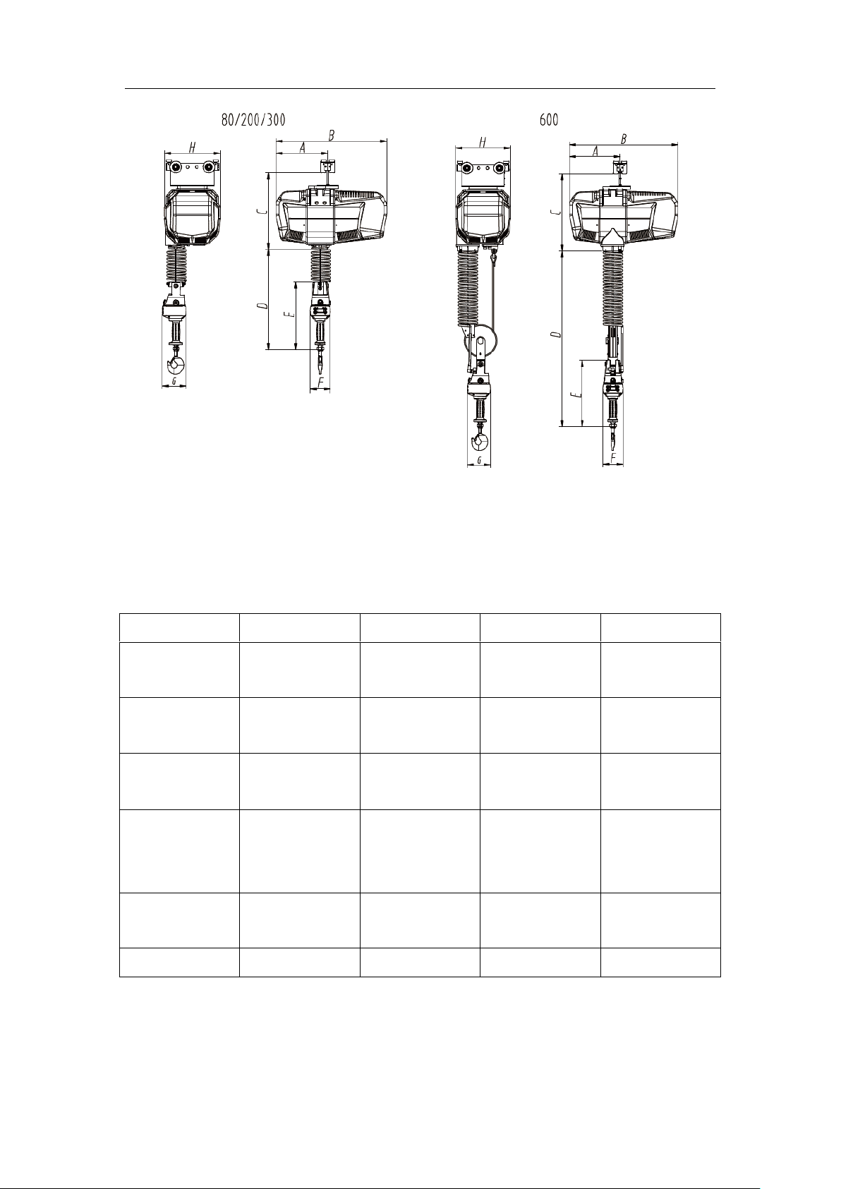
2.11 Basic dimensions
80KG, 200KG, 300KG Intelligence Aided Lifting Equipment Basic Dimensions Table 3 (Fig.
2 10right). See attachments for detailed dimensions.
600KG Intelligence Aided Lifting Equipment Basic Dimensions 3 (Fig. 2 10left). See
attachments for detailed dimensions.
Note: D is the min. size.
Table 3
19
Page 20
Intelligence Aided Lifting Equipment
Model
IAD-H80
IAD-H200
IAD-H300
IAD-H600
Servo drivers
Delta (0.75KW)
Delta (1.5KW)
Delta (2KW)
Delta
(2KW)
Servo motor
Delta (0.75KW)
Delta (1.5KW)
Delta
(2KW)
Delta
(2KW)
Gear reducer
Planetary gear
Planetary gear
Planetary
gear
Planetary
gear
Switching power
supply
LRS-100-24
(MEAN WELL)
LRS-100-24
(MEAN
WELL)
LRS-100-24
(MEAN
WELL)
LRS-100-24
(MEAN
WELL)
Main control
board
Henghui
Henghui
Henghui
Henghui
Structural Parts
Henghui
Henghui
Henghui
Henghui
Fig. 2 10 Dimension
2.12 Main components
Intelligence Aided Lifting Equipment Main Components Information Table 4.
Table 4
20
Page 21
Intelligence Aided Lifting Equipment
Chapter III Start
3.1 Power supply
1. Before final connection to power, check the entire equipment to ensure all connections
are complete without bending or loosening and the following connected shall be
checked:
Connection of spring wire and handle M12 hole socket;
Connection of spring wire and master M12 hole pin socket;
Connection of other wires;
2. Connect the power line to a single-phase 220VAC or three-phase 220VAC power supply.
Note:
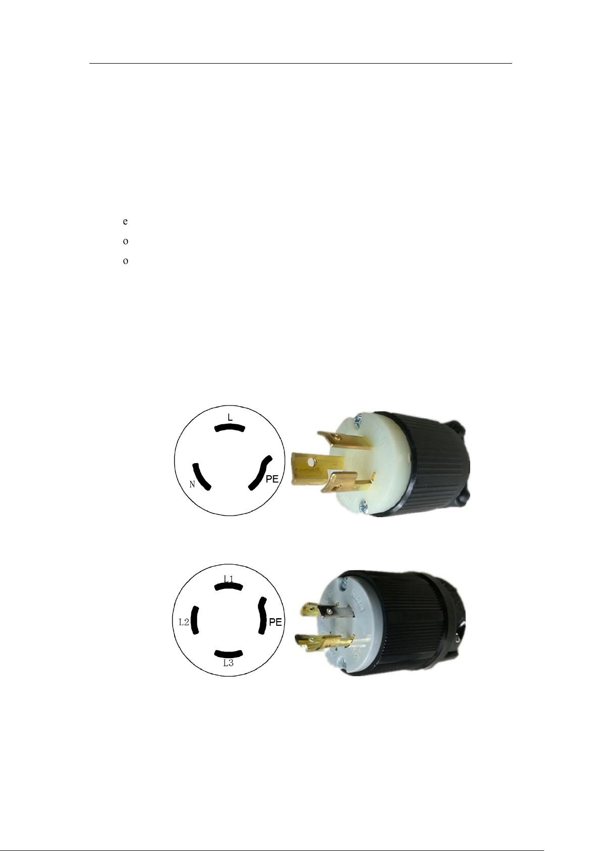
Fig. 3 1: main machine side plug (male connector) for 80KG, 200KG equipment using
single-phase 220VAC (50HZ) power, where L to live wire, N to null line and PE to GND; Fig.
3 2: main machine side plug (male connector) for 300KG, 600KG equipment using
three-phase 220VAC (50HZ) power, where L1, L2, L3 to the three-phase and PE to GND;
Fig. 3 1: single-phase 220VAC main machine plug
Fig. 3 2: three-phase 220VAC main machine plug
Note:
Three-phase 220VAC power supply is provided by the isolation transformer
(three-phase 380VAC three-phase 220VAC, with optional isolation transformer), and the
21
Page 22
Intelligence Aided Lifting Equipment
three-phase 380VAC power supply to the transformer is connected through the circuit
breaker.
3. Connect the main power air plug (female) to the end of the power line.
4. Connect the installed main power air plug (female) to the Intelligence Aided Lifting
Equipment air plug (male).
Note:
The equipment must be grounded.
When the equipment is connected to a power source or a connector, it must not be
powered. Live operation may cause serious or fatal injury to personnel or damage to the
equipment.
3.2 Connection of transformer
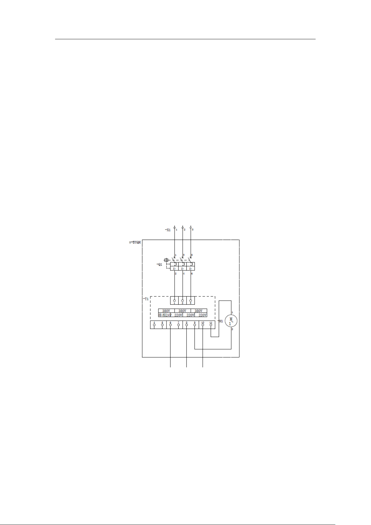
The lifting equipment with a capacity of 300KG and 600KG can be provided with a transformer,
and the connection line of the transformer is shown in 错误!未找到引用源。.
Fig. 3. 3 Connection line of the transformer
22
Page 23
Intelligence Aided Lifting Equipment
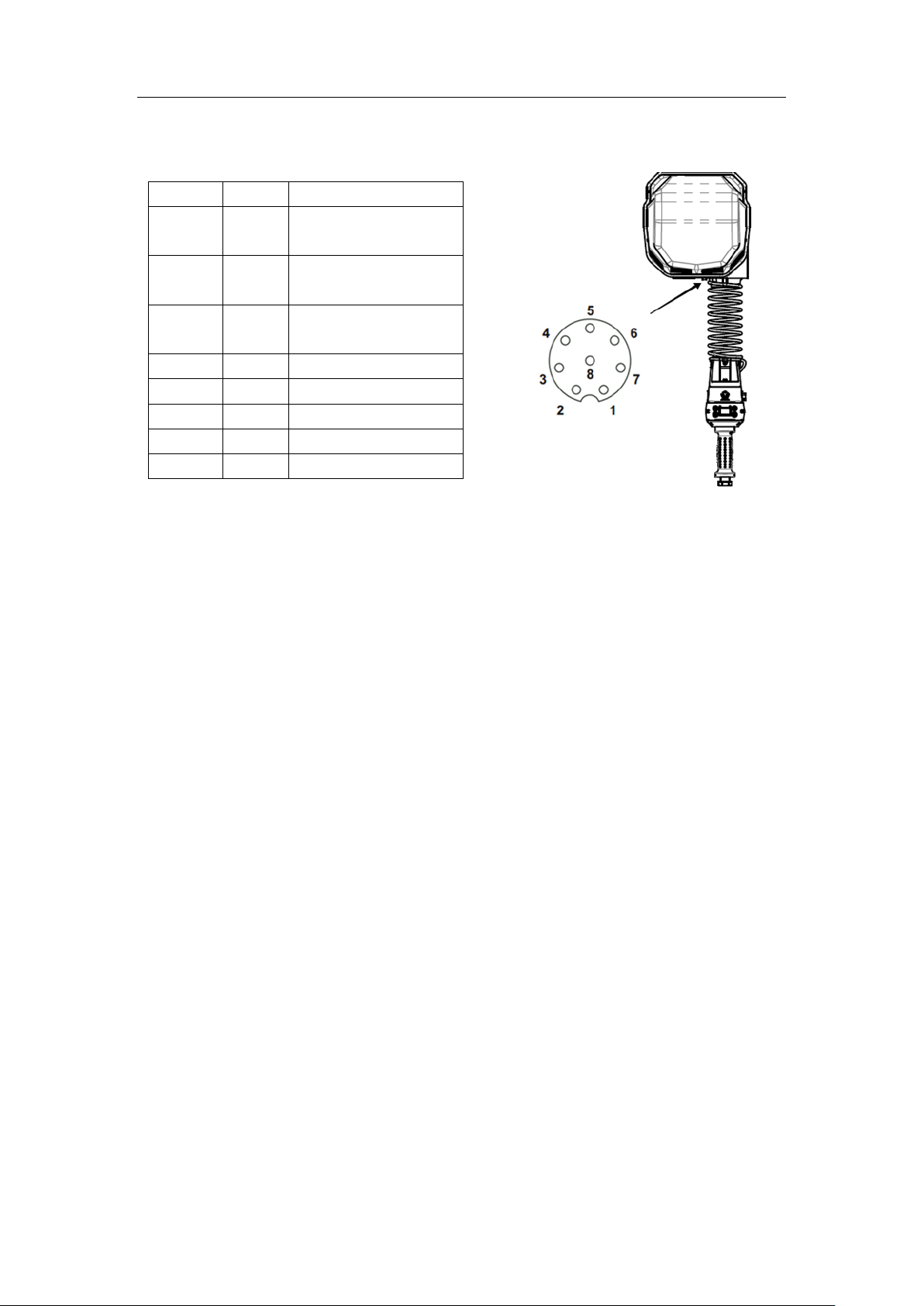
Pin No.
Pin
Description
1
D24V
Common power output
24v
2
CANO
H
CAN communication
high signal
3
CANOL
CAN communication
low signal
4
COM
Common terminal
5
ESTOP
Emergency stop signal
6
PE
Grounding terminal
7
null 8
null
3.3 Description of signal cable pins of the host
3.4 Initial start
1. When the power is turned on and the equipment detects power, “Starting...” is displayed
on the LCD.
2. Release the emergency stop button on the front of the handle.
3. After the system startup is completed, “Position Data”, “Lockup Mode” and “Load Data”
are displayed on the LCD screen.
4. Standard operation - sliding handle: Hold the hand shank sliding handle and adjust
the device up and down, repeat it for several times to feel the moving of device. The
LCD shows “mode of manual hold” and the position data of the handle will be displayed
in the “position data” column. Affected by the acceleration, the load data value will
change slightly.
5. Standard operation - CVT handle: Hold the CVT handle and press the UP/DOWN
buttons to feel the movement of the equipment. The LCD shows “mode of manual hold”
and the position data of the handle will be displayed in the “position data” column.
Affected by the acceleration, the load data value will change slightly.
6. Standard operation - full touch handle: Apply an upward/downward force on the
handle operating end. When the force applied satisfies the set starting operating force
value, the system switches from “locking mode” to “mode of manual hold” and the
device starts to operate. The greater the force applied, the faster the equipment will
operate.
23
Page 24

Intelligence Aided Lifting Equipment
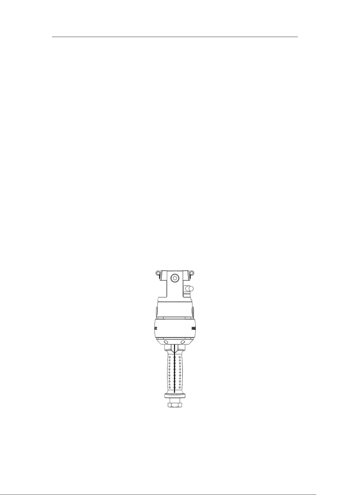
7. Standard operation-coaxial pressure handle: Apply an upward/downward force on
the rubber handle. When the force applied satisfies the set starting operating force value,
the system switches from “locking mode” to “mode of manual hold”, and the equipment
starts to operate. The greater the force applied, the faster the equipment will operate.
24
Page 25
Intelligence Aided Lifting Equipment
Chapter IV Basic function
4.1 Mode of manual hold
4.1.1 Operation mode
When the operator holds the sliding handle, the operation mode of the handle display
switches from the “locking mode” to the “mode of manual hold”. The operator can control the
system up and down movement through sliding handle. The sliding handle has an intermediate
zero position. The farther the operator moves the slide handle from the neutral zero, the faster the
equipment can run up and down.
4.1.2 Infrared sensor
Intelligence Aided Lifting Equipment is provided with infrared sensor (Fig. 4 1). When the
sensor does not detect the operator, the system is in the “lock mode” and the operator cannot move
the system up or down through the sliding handle control system. When the sensor detects the
operator, the system is in the “mode of manual hold” and the operator can move the system up or
down through the sliding handle control system. The system has a manual timeout value setting,
when the sensor detects the operator, but the operator does not operate the sliding handle for a
time longer than the set value, the operator cannot control the system to go up and down at this
time, and the operator needs to leave and re-hold the sliding handle.
Fig. 4 1 Infrared sensor sensing area
4.1.3 Adjust the maximum operating speed in mode of manual hold
In the mode of manual hold, the maximum operating speed is divided into 10 levels, and the
25
Page 26

Intelligence Aided Lifting Equipment
maximum speed in each stage is the number of stages × 10% of the maximum speed. The user
may set the maximum operating speed in the mode of manual hold through the speed setting in the
menu according to the demand. Specific methods of operation are as follows:
1. When the main interface displays “lock mode”, click the “ENT” button to enter the main
menu interface.
2. Use “UP” and “DOWN” to select “Speed Up/Down Adjustment” and click the “ENT”
button to enter its menu.
3. Select “Speed Settings” → “Manual Speed Settings”, select the desired level with “UP”
and “DOWN” and confirm with the “ENT” key.
4. Press the “ENT” button to exit to the main interface. The maximum operating speed
setting in the mode of manual hold is completed.
4.1.4 No-load deceleration function
In practical applications, the operator always expects the load to run stably at a slower speed
from the worktable (pallet, floor) and then return to a higher operating speed. The no-load
deceleration function provides a period of deceleration when the equipment is lifting the load.
When the equipment is lifting the load, the no-load deceleration function will determine
whether it is necessary to perform deceleration operation according to the comparison of the
current load weight value and the preset no-load weight threshold. Where the current load weight
value is less than the preset no-load weight threshold, the equipment will run at the speed stage in
the no-load speed adjustment for the duration in the no-load speed time limit setting, and then
resume to the normal operating speed. If it is within the no-load speed time limit, when the current
load weight value changes are no less than the preset no-load weight threshold, the speed will
return to normal operating speed. When the current load weight value is larger than or equal to the
preset no-load weight threshold, the equipment performs no deceleration function.
Note:
The no-load operating speed can be set as larger than that in a normal operation.
4.1.4.1 Usage mode
1. When the main interface displays “locking mode”, click the "ENT" button to enter the
main menu interface.
2. Select "Lifting Speed Adjustment"→"No-load Speed Setting" and click the "ENT"
button to enter its menu.
3. Enter the "No-load Speed Switch" menu, select "Open" through the "UP" and "DOWN"
buttons, and click the "ENT" button for confirmation and saving.
4. Enter the "No Load Weight Threshold" menu and click the "ENT" button to set the
no-load weight threshold (the set value should be slightly smaller than the lifting load weight);
26
Page 27
Intelligence Aided Lifting Equipment
5. Enter the "No-load Speed Adjustment" menu, select the gear through the "UP" and
"DOWN" buttons, and click the "ENT" button for confirmation and saving;
6. Enter the "No-load Speed Time Limit" menu, select the time limit of no-load operation by
"UP" and "DOWN" buttons, and click the "ENT" button for confirmation and saving.
7.The setting of the no-load deceleration function is completed.
4.2 Suspension mode
In this mode, the operator may raise or lower the load by applying an upward or downward
external force to the load. The greater the force applied, the greater the speed at which the load
moves.
4.2.1 Operation mode
1. Lift the load to the proper height in mode of manual hold.
2. Make sure “suspension setting” → “suspension function switch” in the menu is
“open”.
3. Press the “ENT” button to return to the main interface and move the hand away from the
sliding handle to put the system into “lock mode”.
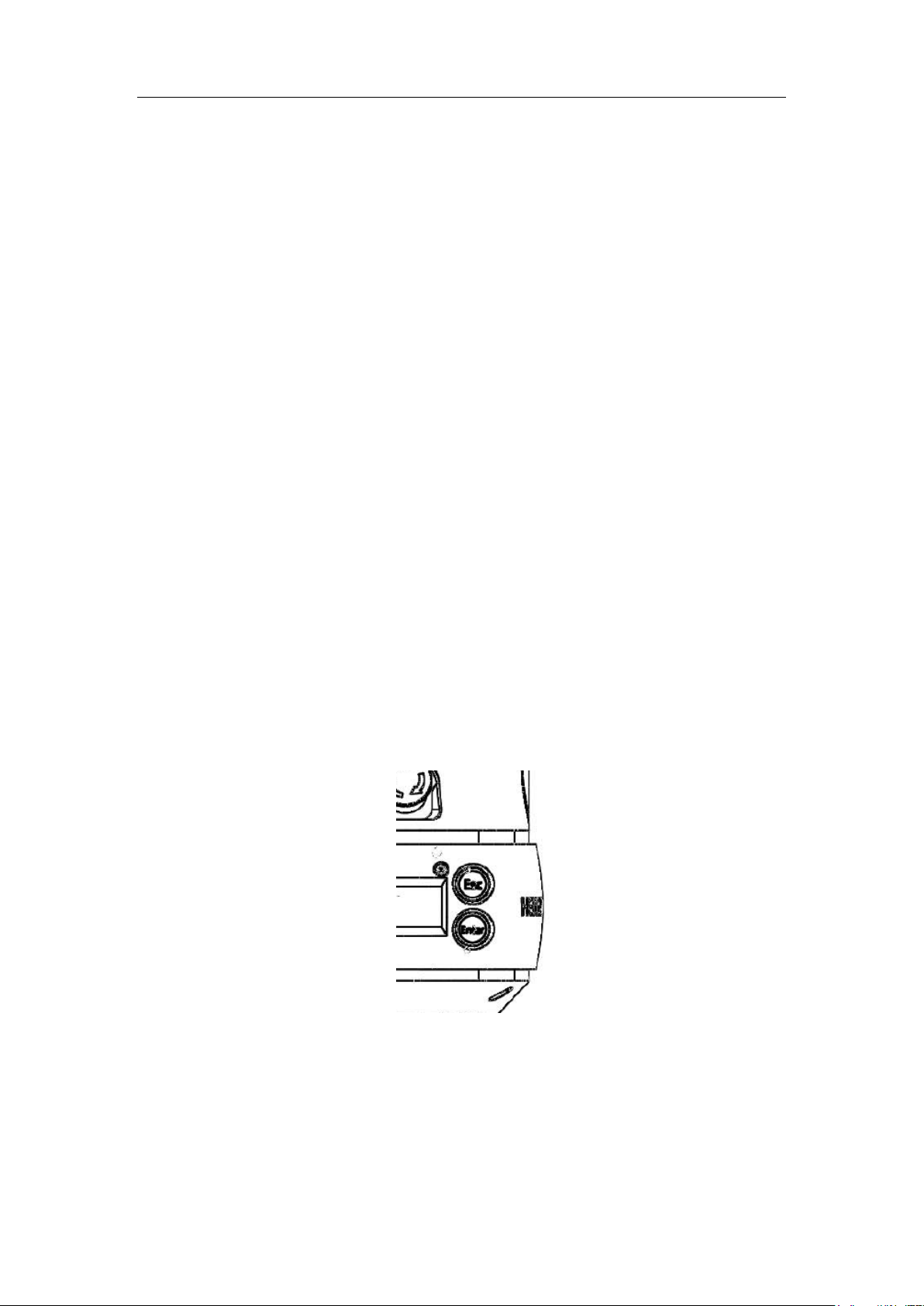
4. Press “ESC” button for seconds (Fig. 4 2), the “lock mode” on the display screen
changes to “suspension mode” at this moment.
5. Grasp the load after the suspension mode is on.
6. Applying an upward force to the load raises the load, and applying a downward force to
the load lowers the load.
7. Repeat several times until you are familiar with the suspension mode.
Fig. 4 2 Suspension button
4.2.2 Notes to suspension mode
1. In suspension mode, triggering the infrared sensor will cause the suspension mode to
exit (i.e., exit when manual hold mode is triggered).
2. Do not apply additional force to the load during start of the suspension mode. The extra
27
Page 28

Intelligence Aided Lifting Equipment
force will cause the system to record a larger or smaller reference weight. After
removing the extra force, the load may move in the opposite direction.
3. In the suspension mode, the system will exit the suspension mode when the operator
does not apply external force to operate the load for longer than the set suspension timeout
value.
4. Every time, the weight of the load changes, the suspension mode shall be restarted.
4.3 Levitation unloading mode
The suspension unloading mode is based on the suspension mode with the unloading function
mode added and such function can easily achieve smooth assembly on the slope in the suspended
state.
4.3.1 Operation steps
You may start the suspended unloading mode up by directly pressing the “UP” bottom on the
handle for seconds (about 2 seconds). If you are not familiar with the mode, you may exercise the
operation first.
1. Enter the suspension unloading mode (operation procedure refers to the operation
procedures of suspension mode).
2. After starting, hold the load and move it down so that the bottom part of the weight
contacts with the ramp (up to over-power for more than 1s). At this time, the green indicator
blinks quickly and the unloading mode is displayed.
3. Continue to apply a downward force to the load and let it fall slowly until the entire
bottom of the weight contacts the ramp.
4. Repeat the above exercise until you are familiar with the suspension unloading mode.
4.3.2 Suspension unloading mode description
1. When using the suspended unloading mode, the anti-rebound mode shall be over-power.
2. The smaller the upward over-power value is set, the easier it is to enter the unloading
mode from the suspension unloading mode.
4.4 Automatic suspension function
This feature allows the lifting equipment to automatically enter the suspension mode without
pressing the “ESC” button when the load meets the following conditions.
Detection weight: Used to determine the weight conditions for entering the automatic
suspension. | Load weight - Detection weight | <= Operating force - 0.5. If the set detection weight
is 50KG and the operating force threshold is set to 2KG, the weight condition for entering the
automatic suspension mode is 48.5-51.5KG.
Detection time: Used to determine the time conditions for entering the automatic suspension.
28
Page 29

Intelligence Aided Lifting Equipment
If the detection time is set to 2 seconds, the system will automatically enter the suspension mode
when the load weight meets the automatic suspension condition for 2 seconds.
4.4.1 Operation steps
1. Enter the suspension setting menu and set the suspension function switch to ON;
2. In the “suspension setting” →“automatic suspension”, choose “open”;
3. In the “suspension setting” →“automatic suspension” →“detection weight” →
“detection weight 1”, press “ENT” to save the current load weight value;
4. According to the actual situation, repeat the previous step to complete the setting of
multiple different detection weights (up to 10 groups of weight intervals can be set);
5. In the “suspension setting” →“automatic suspension” →“detection time”, set the
desired time and press “ENT” to save the setting;
6. After the setting is completed, when the load satisfies any set value of the detected
weight, and the set detection time is reached, the system automatically enters the
suspension mode.
Note:
In the menu where the detection weight value has been set, select “Invalid” by pressing “UP”
button, and then press “ESC” to exit. The saved detection weight will be reset to invalid.
If there are multiple objects in the application, where (maximum weight-minimum weight)
<= (2 × operating force threshold - 1), the automatic suspension function can be achieved with
only one detection weight number. The detection weight is set to the average of its maximum
weight and minimum weight.
4.5 Unloading function
This function allows the user to operate the lifting equipment to directly perform the
unloading mode. In this mode, the equipment is in a suspended state. The user can only
intermittently press the load downwardly, so that the load intermittently moves downwards
vertically and automatically when the load contacts the bottom surface to complete the unloading.
4.5.1 Operation Method
When the equipment is normal, press the “Down” button for about 2 seconds. The system
will directly perform the unloading mode when the green light will flash. (For the coaxial handle,
do not trigger the infrared sensor; for the stepless handle, do not press Up and Down buttons).
Press the load a little harder, the load will automatically move down a certain distance, then
press again, the load will move down a distance again ... until the load completes the plane
assembly.
Unloading speed setting: Set the speed level parameter in “Upgrade Speed Adjustment” →
29
Page 30

Intelligence Aided Lifting Equipment
“Speed Setting” → “Unloading Speed”.
4.6 Soft limit
The intelligence aided lifting equipment is equipped with a soft limit function, which can
easily achieve 5 functions, fixed-point upper limit, lower limit, downward deceleration, upward
deceleration, and upward speed recovery. The soft limit has two sets - soft limit 1 and soft limit 2.
When the limit switching mode is signal switching, the parameters in soft limit 1 and soft limit 2
which are set in the mode of manual hold, the suspension mode, the suspension unloading mode,
and the unloading mode are all valid, and the related functions in the soft limit 2 are required to be
achieved by the double limit switching in the extended function. When the limit switching mode is
mode switching, the setting parameters in soft limit 1 are valid only in the mode of manual hold,
and the setting parameters in soft limit 2 are valid only in the suspension mode, suspension
unloading mode and unloading mode and the double limit function in the extended function will
not work in such mode. By default, the limit switching mode is signal switching.
4.6.1 Operation steps
Take the upper soft limit setting in soft limit 1 as an example:
1. The operation load moves to the soft limit position to be set.
2. When the main interface displays “lock mode”, click the “ENT” button to enter the main
menu interface.
3. Use “UP” and “DOWN” to select “soft limit” and click the “ENT” button to enter its
menu.
4. Select “soft limit 1” → “soft limit”, click the “ENT” button to keep the current position,
and the display shows “setting successful”;
5. When the operation load is again moved from the bottom to the set position, the system
stops operating.
4.6.2 Precautions
When using soft limit, the following points need to be understood by the user.
1. When the equipment reaches the upper soft limit position and the lower soft limit
position, the system stops its operation and can only move in the opposite direction.
2. When the system does not set the slowdown point, the system decelerates automatically
when the system default distance is about 13cm from the upper (lower) limit point at full
speed; the deceleration distance of the system becomes shorter as the speed decreases.
3. When the upper soft limit and lower soft limit set points coincide, the equipment will
not move.
4. The upward slowdown point shall be set below the upward speed recovery point. If it is
30
Page 31
Intelligence Aided Lifting Equipment
set at the top, it will lose its effect.
5. If the slowdown point is set to reduce the impact of load docking in the air, you must
ensure that the load is set at the slowdown point before the docking point and the slowdown
point must be at least 10 cm away from the docking point.
6. The soft limit configuration has a separate reset function. In the corresponding function
interface, click the “UP” button to select “invalid” and then press the exit button “ESC” and
the separate reset is done.
7. Soft limit is configured with “Reset soft limit” menu, select reset, all soft limit resets are
“invalid”.
8. The deceleration speed in soft limit is 1.8 m/min.
4.7 Inching button operation
Only the qualified personnel can use the inching button when changing steel wire ropes.
Effective use of inching button must require the equipment to be normally energized. The inching
button may be used as follows:
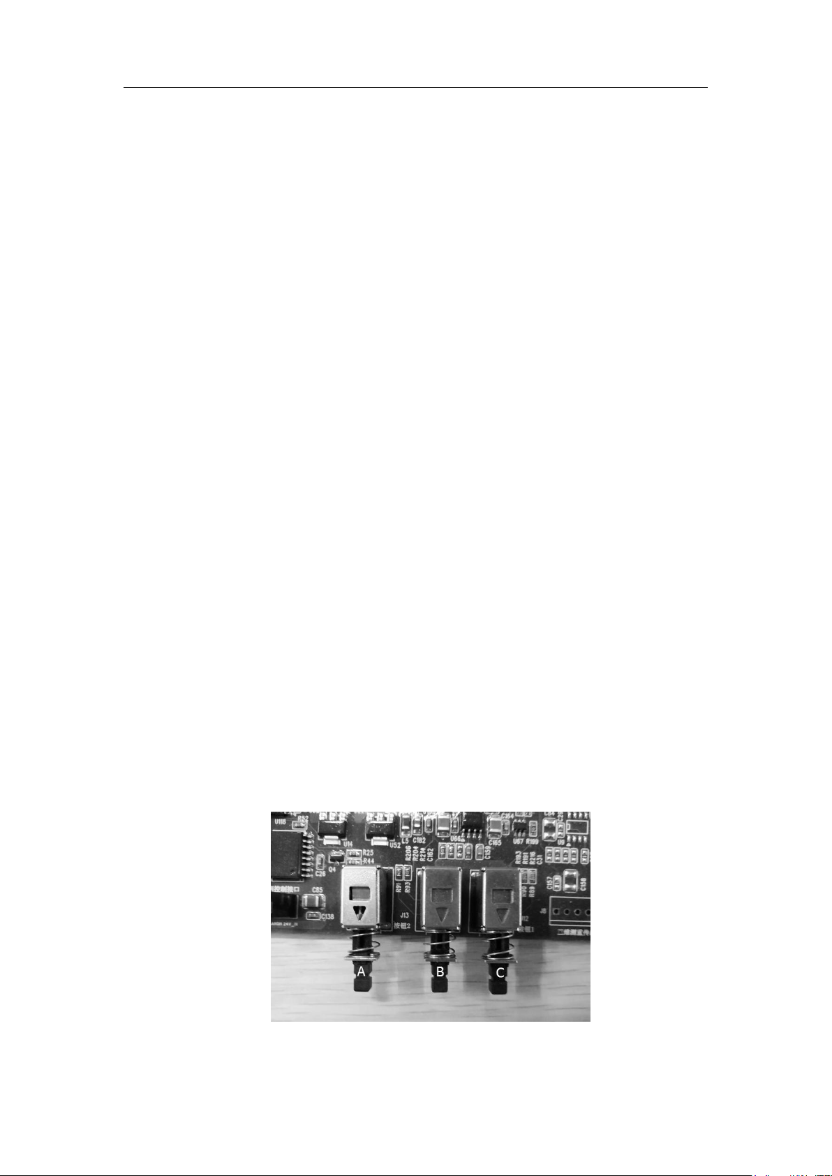
1. Press the button A (self-locking), buttons B, C (Fig. 4 3) and then the operation works.
2. Pressing the upward inching button B (self-recovery) will start the motor and cause the
system to roll the wire rope onto the drum.
3. Pressing the downward inching button C (self-recovery) will start the motor and cause
the system to roll the wire rope down from the drum.
Note:
When the wire rope is replaced, the wire rope must always be perpendicular to the wire rope
jacket mouth whether it is rolled in or rolled out.
When the wire rope is replaced, the wire rope must be under tension (greater than 50N).
For detailed steps, please see the “Instructions on Wire Rope Replacement” and the
video named “Replacement Of Steel Wire Ropes” for reference.
Fig. 4 3 Inching button
31
Page 32
Intelligence Aided Lifting Equipment
4 3 2
1
Mode of manual hold
Locking mode
Suspension (suspension
unloading, unloading)
5
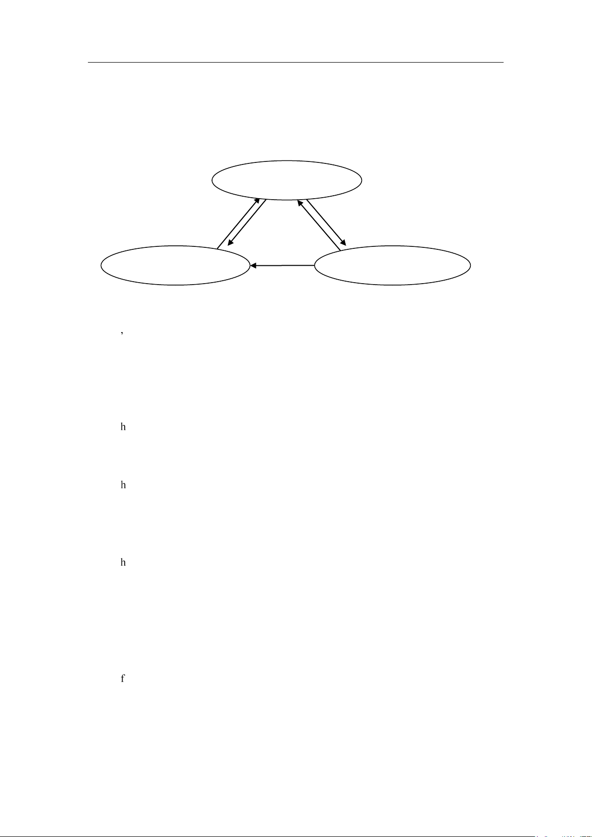
Fig. 4 4 Mode switch
4.8 Function switch
The equipment lifting control module is switched among the three modes of “locking mode”,
“mode of manual hold”, and “suspension (suspension unloading, and unloading) mode” (Fig. 4 4),
each state responds to external signals and makes different controls.
Under the following several conditions the “mode of manual hold” may be switched to
“locking mode”.
1. Holding the infrared sensor without signal.
2. The IR sensor has a signal when held manually, but the handle position sensor is zero
and the time exceeds the manual timeout setting.
Under the following several conditions the “locking mode” may be switched to “mode of
manual hold”.
1. When there is no alarm, the infrared sensor is held from no signal to having a signal.
From “suspension (suspension unloading, unloading) mode” to “locking mode”
1. No operation suspension mode shall exceed the set value.
2. The manual moving load speed exceeds the maximum suspension speed by 90%
(over-speed).
Under the following several conditions the “locking mode” may be switched to
“suspension (suspension unloading, unloading) mode”.
1. When there is no alarm, long press the “ESC” button on the handle for about 2 seconds
to enter the suspension mode, or long press the “UP” button on the handle for about 2
seconds to enter the suspension mode, or long press the “DOWN” button on the handle
for about 2 seconds to enter the suspension mode.
Under the following several conditions the “suspension (suspension unloading, unloading)
mode” may be switched to “mode of manual hold”.
1. Trigger the infrared sensor.
32
Page 33

Intelligence Aided Lifting Equipment
Chapter V Extended Function
Henghui Intelligence Aided Lifting Equipment may achieve the following extended functions
through the extended port IO:
Inching function, mode switch, double limit function, double suspension function,
automatic homing function, anti-drop function, stacking function
The extended function needs to configure the IO port that the expansion port needs, and input
(output) the required signal through the configured IO port in order to use normally. The extended
port provided by Henghui Intelligent Lifting Equipment includes the following types: Main
machine extended port, handle extended port and external extended module. The user may select
the suitable extended port according to actual conditions.
The extended port IO required for the extended function can be configured by the user. All
extended ports IO ports of Henghui Intelligent Lifting Equipment have the respective and sole
number, easy to be set by user. (No. 0 is invalid for setting IO)
5.1 Inching function
By controlling the IO signal of the extension interface, the equipment can run at four constant
speeds: slow gear upwards, slow gear downwards, fast gear upwards and fast gear downwards. In
the “lifting speed adjustment” → “setting of inching speed”, the speed of the fast/slow gear can
be set by “inching fast gear” and “inching slow gear”.
5.1.1 Usage mode
The control signals of the fast/slow gears can be input through interfaces on the host
extension board, handle extension board, or expansion board. In the "Expansion Function Setting"
→"Expansion Interface Setting", the corresponding IO numbers for "Slow Gear Upwards", "Slow
Gear Downwards", "Fast Gear Upwards" and "Fast Gear Downwards" can be set.
For example: Set the 9th, 10th, 11th and 12th pins on the extension interface of the coaxial
handle as the inputs of "Slow Gear Upwards", "Slow Gear Downwards", "Fast Gear Upwards" and
"Fast Gear Downwards". Connect the 9th pin and the 6th pin on the handle extension interface to
the normally open contacts of Switch K1 (self-recovery), and then set the IO number to 12 in the
"Slow Gear Upwards" menu. Connect the 10th pin and the 6th pin to the normally open contacts of
Switch K2 (self-recovery), and then set the IO number to 13 in the "Slow Gear Downwards" menu.
Connect the 11th pin and the 6th pin to the normally open contacts of Switch K3 (self-recovery),
then set the IO number to 14 in the "Fast Gear Upwards" menu. Connect the 12th pin and the 6th
pin to the normally open contacts of Switch K4 (self-recovery), and then set the IO number to 15
in the "Fast Gear Downwards" menu. When the contacts of Switch K1 are connected, the
33
Page 34

Intelligence Aided Lifting Equipment
equipment will run at a "Slow Gear Upwards" speed, and when the contacts of Switch K1 are
disconnected, the equipment will stop. When the contacts of Switch K2 are connected, the
equipment will run at a "Slow Gear Downwards" speed, and when contacts of Switch K2 are
disconnected, the equipment will stop. When the contacts of Switch K3 are connected, the
equipment will run at a "Fast Gear Upwards" speed, and when contacts of Switch K4 are
disconnected, the equipment will stop. When the contacts of Switch K2 are connected, the
equipment will run at a "Fast Gear Downwards" speed, and when contacts of Switch K2 are
disconnected, the equipment will stop.
5.1.2 Fast gear and slow gear speed adjustment
The fast/slow gear speeds can be divided into 10 levels: the speed of each level is the level
number multiplied with 10% maximum speed. The user can set the fast/slow gear speeds through
the inching speed setting in the menu, by the following operations:
1. When the main interface displays “locking mode” (or “emergency stop mode”), click
“ENT” button to enter the main menu;
2. Select “lifting speed setting” with UP/DOWN, and click “ENT” button to enter its
menu;
3. Select “inching speed setting” → “fast gear setting” or “slow gear setting”, and select
the desired speed level with UP/DOWN, and click “ENT” button for confirmation; and
4. Press the “ESC” button to exit the main interface, and complete the setting of fast/slow
gear speed.
5.2 Switching of modes
When in a “locking mode”, the equipment can switch from the “locking mode” to the
“suspension mode”, or to “suspension unloading mode”, or to “unloading mode”. When the mode
is switched, select “open” in “suspension setting” → “suspension function switch”.
5.2.1 Usage mode
The control signal for the mode switching can be input by the host extension, handle
extension, or expansion board input port. Set the corresponding IO numbers in “Extended
Function Setting” → “Extended Port Setting” → “Switch Double Limit”.
For example: take the 9th, 10th and 11th pins on the extension interfaces of the coaxial handle
as the inputs for the switching from the “locking mode” to the “suspension mode”, the switching
from the “locking mode” to the “suspension unloading mode”, and the switching from the
“locking mode” to the “unloading mode” respectively. Connect the 9th pin and the 6th pin on the
34
Page 35

Intelligence Aided Lifting Equipment
extension interfaces of the handle to the normally-open contacts of Switch K1 (self-recovery), and
set the IO number to 12 in the “switch to suspension mode” menu. Connect the 10th pin and the 6th
pin on the extension interfaces of the handle to the normally-open contacts of Switch K2
(self-recovery), and set the IO number to 13 in the “switch to suspension unloading mode” menu.
Connect the 11th pin and the 6th pin on the extension interfaces of the handle to the normally-open
contacts of Switch K3 (self-recovery), and set the IO number to 15 in the “switch to unloading
mode” menu. When the contacts of the inching switch K1 is connected in a “locking mode”, the
equipment switches from the “locking mode” to the “suspension mode”. When the contacts of the
inching switch K2 is connected in a “locking mode”, the equipment switches from the “locking
mode” to the “suspension unloading mode”. When the contacts of the inching switch K3 is
connected in a “locking mode”, the equipment switches from the “locking mode” to the
“unloading mode”.
5.3 Double limit function
The equipment only uses the setting parameters in the soft limit 1 by default. By configuring
the IO signal of the extended port, the system can use the setting parameters in the soft limit 1 or
soft limit 2. By controlling the input of the extended port IO signal, the user can easily implement
the switching between the soft limit 1 or 2 of the lifting equipment, which is suitable for the user’s
changing requirements for soft limit in the application.
5.3.1 Usage Method
The switching double limit signal can be input by the host extension, handle extension, or
expansion board input port. Set the corresponding IO number in “Extended Function Settings” →
“Extended Port Settings” → “Switch Double Limits”.
For example: Take the 11th pin of the handle extension interface as the double limit signal
input. Connect the 11th and 6th pins of the handle extension interface to the normally open contacts
of the (self-recovery) switch, and then set the IO number to 14 in “Switching Double Limits”.
When the switch contact is turned on, the soft limit used by the system is switched from soft limit
1 to soft limit 2. When the button is triggered again, the soft limit used by the system is switched
from soft limit 2 to soft limit 1. With the trigger of the button, the limit used by the system is
cyclically switched between soft limit 1 and soft limit.
Note:
The function and parameter setting method of soft limit 2 is the same as soft limit 1.
When double limits are used, the soft limit mode switch must be selected as the signal
switch!
35
Page 36

Intelligence Aided Lifting Equipment
5.4 Double suspension function
The double suspension function allows the equipment to remain in the suspension mode at all
times, and realizes the suspension load switching between the fixture weight and fixture + work
piece weight, and is particularly suitable for the positional installation of the work piece in the
suspended state. The switching operation between the double suspension functions shall set the IO
signal of the extended function, and shall access the switch or sensor according to different
working modes.
The implementation of the double suspension function requires that the system presets the
load weights in two kinds of suspended states, and then set different extended IO signals
according to the selected double suspension mode.
Note:
Regardless of the mode in which double suspension works, the equipment load must
meet the following conditions: If |Load weight - (any) pre-set the weight value| <= (operating
force - 0.5), it can normally start and enter into the double suspended state!
Double suspension is divided into fixture suspension and fixture work piece suspension.
5.4.1 Double suspension weight setting
① Perform submenus for “Extended Function Setting” → “Double Suspension Setting”;
② From the double suspension setup menu, enter the “fixture weight” submenu. When the
equipment hangs the fixture and remains stable, click “ENT” button to record the weight
of the fixture (the maximum fixture weight can be set to 60KG);
③ Same as the previous step, in the “fixture work piece weight”, the jig work piece is
suspended and remains stable, and the “fixture work piece weight” is recorded; click
“ESC” button to return to the previous menu.
5.4.2 Double suspension mode setting
The double suspension function enters the double suspended state mode according to the
entering equipment, and is divided into two types: automatic and manual.
Enter “extended function setting” → “double suspension setting” → “double suspension
mode” submenu in the handle to complete the selection of double suspension mode.
In the automatic mode, the detection time must be set first. When the load weight of the
equipment (fixture or fixture work piece) is in the weight range required to enter the double
suspension mode, and when the accumulated time reaches the set detection time, then the
equipment automatically enters the double suspension mode.
In the manual mode, the equipment must be manually operated to enter the double suspension
mode. According to the set signal selection, the user shall hold the button signal for about 2
36
Page 37

Intelligence Aided Lifting Equipment
seconds to enter the double suspended state.
5.4.3 Signal selection
The two suspended states in the double suspension function are controlled by the configured
signal. Henghui Intelligent Lifting Equipment provides the following three switching signals:
Single signal, dual signal and fixture signal.
Single signal and dual signal are generally triggered manually by the operator to switch
between two suspended states. The fixture signal then switches the suspended state by the
clamping and releasing feedback sensor (switch) mounted on the fixture. Automatic switching of
double suspended state can be achieved if the fixture signal is used.
5.4.3.1 Single (Dual) signal setting
① In the “Extended Function Setting” → “Double Suspension Setting” → “Signal
Selection”, set the switching signal type, and select “Single Signal” or “Dual Signal” for
manual switching as required.
② According to the selected switching signal type and the actual wiring in the host
expansion, handle extension or expansion board input port. If using “single signal”
switching, you need to set the corresponding IO number in “Extended Function
Settings”, “Extended Port Settings”, and “Switching Double Suspension 1”; if using
“Dual Signal” switching, you need to set “Switching Double Suspension 1” and
“Switching Double Suspension 2” IO number, simultaneously.
For example: Take the Pin 11 and Pin 12 of the coaxial handle extended port as the
double suspension startup signal input end. Connect the Pin 11 and Pin 6 of the handle
extended port to the normally open contacts of the switch K1 (self-recovery), and then
set the IO number 12 in “switching double suspension 1”. Connect the Pin 12 and Pin 6
of the handle extended port to the normally open contacts of the switch K2
(self-recovery), and then set the IO number 13 in “switching double suspension 2”.
③ When the set signal selects “single signal”, it is necessary to press and hold (about 2s)
the switch K1 when entering double suspended state. When switching the double
suspended state, only the switch K1 needs to be triggered; if the set signal selects “dual
signal”, press the switch K1 when entering the double suspension mode, and then press
and hold (about 2s) the switch K2. When switching the double suspended state, you
need to press the switch K1 first, and then trigger the switch K2 to switch normally.
“Dual signal” can increase the security of the operation.
5.4.3.2 Fixture signal setting
When the double suspension is switched using the fixture signal, if in the manual mode, the
system must set three (3) IO input signals, which are: switching double suspension 1, clamping
37
Page 38

Intelligence Aided Lifting Equipment
signal feedback and release signal feedback. In the automatic mode, the system must set two (2)
IO input signals, which are: clamping signal feedback and release signal feedback.
Signal setting method:
① The dual suspension signal can be input through host expansion, handle expansion or
expansion board input interfaces. Corresponding IO number can be set through
“expansion function setup”, “extension interface setup” → “ switching dual
suspension 1”.
For example: The Pin 9 of coaxial handle extension interfaces should be used as the
activating signal input end of dual suspension. Connect Pin 9 and 6 of the handle
extension interface to the normally open contacts of the (self-healing) switch, and then
set the IO number to 12 in "Switch dual suspension 1".
② Set the corresponding IO number in "Extended Function Settings" → "Expansion
Interface Settings" → "Clamp Signal Feedback" and "Release Signal Feedback".
For example: Set the Pin 10 of the handle extension interface as the clamp signal
feedback input and Pin 11 as the release signal feedback input end. Connect the Pin 10
of the handle extension interface to the output interface of the clamp sensor (NPN) (or
connect the Pin 10 and Pin 6 to the normally open contact of the clamp switch) and
connect the Pin 11 to the output port of the release sensor (NPN) (or link Pin 10 and Pin
6 to the normally open contact of the release switch). Then set the IO No. to 13 in
“Clamp signal feedback” and 14 in “Release signal feedback”. When the clamping
action is completed, the clamp sensor outputs correspondingly (clamp switch closed);
when the clamp release action is completed, the release sensor output correspondingly
(the release switch closed).
Note:
When using the sensor, the sensor power supply must adopt the DC 24v power
supplied by the extension interface.
Signal instructions:
1. When setting single signal switching, you must set “Switch to Dual Suspension 1”;
when setting the dual signal, you need to set “Switch to Dual Suspension 1” and “Switch
to Dual Suspension 2” at the same time.
2. If manual mode is used for dual-suspension, the signal setting button needs to be pressed
for the first time (self-recovering) [single/double] for about 2 seconds to enter
dual-suspension mode, and the system will automatically enter the fixture work piece
suspension state or fixture suspension state according to the received clamp/release
feedback signal.
38
Page 39

Intelligence Aided Lifting Equipment
3. If manual mode is used for dual-suspension, the system will automatically enter the
fixture work piece suspension state or fixture suspension state according to the received
clamp/release feedback signal.
4. When the system receives the clamping feedback signal, it automatically switches into
the fixture work piece suspension state.
5. When the system receives the releasing feedback signal, it automatically switches into
the fixture suspension state.
5.4.4 Protection settings for dual suspension
The dual suspension function can provide the position protection function, as the user can set
the function within the specific position range, and then the dual suspension switching can be
effective. After the setting is completed, the system is only allowed to be switched to "fixture work
piece” suspension when it is set between the “low seizing position” and the “high seizing position”,
and can be switched to “fixture” suspension when it is set between “low unload position” and
“high unload position”.
Setting method:
1. Enter the “Extended Function Settings” → “Dual Suspension Setting” → “Dual
Suspension Protection” → “Protection Switch” submenu, select “Open” and then click
“ENT” to return to the previous menu.
2. In the clamping station, set values for “low seizing position” and the “high seizing
position” in the “dual suspension protection” menu according to the actual situation.
3. Same as above, set values for the “high unloading position" and "low unloading
position" in the unloading position.
5.4.4.1 Functional instructions
1. The protection function is only valid for single (dual) signals, and the position protection
function is invalid when using the "fixture signal";
2. When dual-suspension protection is set, then the user is only allowed to switch to the
“fixture weight” suspension state when the load position is between “high unloading
position” and “low unloading position”; while the user is only allowed switch to the
“fixture work piece weight” suspension when the load position is between “high seizing
position” and “low seizing position”. For other positions, the user is not allowed to
perform the switching operation to suspension state.
5.5 Anti-drop function
The anti-drop function can prevent the user from accidentally pressing the clamp release
button during the movement of heavy objects, resulting in heavy objects falling and causing
39
Page 40

Intelligence Aided Lifting Equipment
Current load weight value <
anti-drop threshold value
Clamping
feedback signal
Release
signal input
Running status
0 0 Cannot run upwards, but
can run downwards
damage to the equipment or personnel.
The anti-drop function controls the output signal by detecting the relationship between the
weight of the load and the set anti-drop threshold value (weight value) to achieve protection. If the
load weight value < anti-fall threshold value, then the output signal is 0V, and the coil is energized;
If the load weight value ≥ anti-fall threshold value, then the output signal is 24V, and the coil is
de-energized.
5.5.1 Anti-drop threshold setting
1. Enter the “Extended Function Setting” → “Anti-drop Setting” → “Anti-drop
Threshold Value” menu.
2. Set the anti-drop threshold weight by the “ENT” button; (generally, the set threshold
value is slightly larger than the weight of fixtures).
5.5.2 Signal setting
The control of anti-drop function system relies on setting IO signals: the release signal is
controlled by the handle extension interface or the extension interface on expansion board (the
host does not support the output signal temporarily); set the corresponding IO number in
“Extended Function Setting” > “Expansion Interface Setting”> “Release Signal Output”.
For example: The Pin 4 of the handle extension interface is used as the release signal output.
Link Pin 4 and Pin 1 to the outer coil KM1 (such as relay). In the “Release Signal Output”, set IO
number to 24. If the load weight value < anti-drop threshold value, then the coil KM1 has 24V
power supply; If the load weight value ≥ anti- drop threshold value, then the coil KM1 loses
power.
5.5.3 Clamping protection function
The anti-drop function may be added with the clamping feedback signal and release signal
input to ensure that the device is completely clamping before lifting. If the system has received the
clamping signal feedback, the device can run upwards as well as downwards. If the system fails to
receive the clamping signal feedback and the release input signal, the device cannot run upwards
but may downwards. When the system fails to receive the clamping signal feedback, but has
received the release input signal, if the current load weight value < anti-drop threshold value, then
the device can run upwards but cannot downwards; if the current load weight value ≥ anti- drop
threshold value, then the device cannot run upwards but may downwards.
40
Page 41
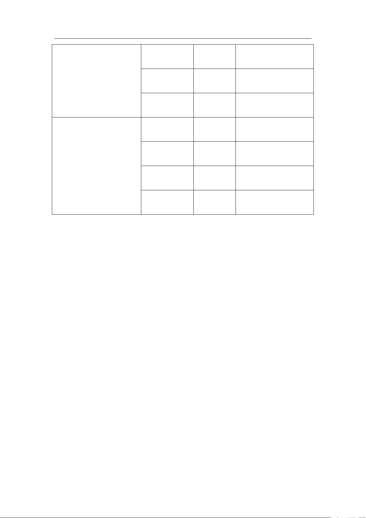
Intelligence Aided Lifting Equipment
1 0 Can run upwards and
downwards
1 1 Can run upwards and
downwards
0 1 Can run upwards and
downwards
Current load weight value ≥
anti- drop threshold value
0 0 Cannot run upwards, but
can run downwards
1 0 Can run upwards and
downwards
1 1 Can run upwards and
downwards
0 1 Cannot run upwards, but
can run downwards
0 means no signal and 1 means there is signal.
Note:
The release signal input connects to the normally closed pins of release buttons.
When the above operations fail, a warm like “Abnormal Clamping Signal” would be
displayed on the screen.
The anti-dropping function may not employ the clamping signal feedback and release signal
input, in such cases, the IO number of the corresponding menu in the extension interface setting
shall be set to 0.
5.5.3.1 Signal setting:
① The control of anti-drop function system (added with clamping protection function)
relies on setting IO signals: Clamping signal feedback and release signal input can be
conducted through the extension interface of the host, handle or expansion board; set the
corresponding IO No. in the “Extended Function Setting” → “Expansion Interface
Setting” → “Clamping Signal Feedback” → “Release Signal Input”; the output signal
is controlled by the handle extension interface or the extension interface on expansion
board (the host does not support the output signal temporarily); set the corresponding IO
number in “Extended Function Settings” → "Expansion Interface Setting" → "Release
Signal Output".
For example: The Pin 9 of the handle extension interface is used as the clamping signal
feedback, while the Pin 10 is used as the release signal input, and Pin 4 as the release
signal output. Connect Pin 9 and Pin 6 of the handle extension interface to the normally
41
Page 42

Intelligence Aided Lifting Equipment
open contact of the clamp feedback switch, and link Pin 10 and Pin 6 to the normally
closed contact of the release button, and link Pin 4 and Pin 1 to the outer coil KM1 (such
as relay). In the “Extended Interface Settings”, set IO number of the clamp signal
feedback to 12, release signal input to 13, and release signal output to 24.
Note:
The coil power output from the handle extension interface shall be no higher than 12W.
The output of the expansion board is output of the relay contact.
5.6 Auto homing function
This function allows the equipment to automatically return to the pre-set homing position at
the set homing speed by triggering the auto homing signal. To enable the automatic homing
function, the automatic homing load weight and homing speed must be set first. The device will
not automatically return to home poison or stop the homing motion if the device meets with
resistance (causing the load weight more than the pre-set 15KG) when the homing function is
activated or during its homing action.
Note:
Set the homing speed to 5 in “Lifting Speed Adjustment” → “Speed Setting” → “Homing
Speed Setting”.
5.6.1 Homing Weight Setting
1. Enter the “Extended Function Setting” → “Homing Setting” menu.
2. Enter the submenu of “Fixture Weight” from the menu of “Homing Setting”, and then
press “ENT” button to record the homing weight (the maximum homing weight can be
set to 60KG) when the equipment is hung with the homing load and remains stable.
5.6.2 Usage method
Automatic homing signals can be input by the can be input through interfaces on the host
extension board, handle extension board, or expansion board. Set the corresponding IO number in
“Extended Function Setting” → “Expansion Interface Setting” → “Auto Homing”.
For example: Take Pin 11 of the handle extension interface as the auto homing signal input
terminal. Connect Pin 11 and Pin 6 of the handle extension interface to the normally open contacts
of the switch (self-recovery), and then set the IO number to 14 in “Switch to Double Limit”. When
the switch contact is open, the equipment returns to the homing position at the homing speed
5.7 Palletizing function
This function can realize the level-to-level precise stop of lifting equipment through the input
of palletizing signal. Before using this function, users need to set the layer height in advance, and
then the loads automatically stops running when the operating handle is moved up or down to the
42
Page 43

Intelligence Aided Lifting Equipment
set position layer. If you need to continue to operate the equipment to the upper level or the lower
level, you need to operate the handle to the zero position2 first, and then conduct the up or down
movement to lift the equipment to the next layer, and which would automatically cease movement.
Operate the equipment in turn, so as to achieve precise stop of the equipment at each layer.
Note:
Spacing between adjacent stops must be greater than 20 mm.
5.7.1 Signal setting
The palletizing signal can be input through interfaces on the host extension board, handle
extension board, or expansion board. Set the corresponding IO number in “Extended Function
Settings” → “Extended Interface Settings” → “Palletizing Signal Input”.
For example: Take Pin 11 of the coaxial handle extension interface as the palletizing signal
input terminal. Connect Pin 12 and Pin 6 of the handle extension interface to the normally open
contacts of the switch (self-locking/self-recovery), and then set the IO number to 12 in "Palletizing
Signal Input”; when the switch contact is on, the palletizing signal input has a signal, and the
palletizing function is valid; when the switch contact is open, the palletizing signal input has no
signal, and the palletizing function is invalid.
5.7.2 Operation steps
1. Turn on the input switch contact of the external palletizing signal; (The layer setting can
be completed first, then the signal settings to facilitate the layer height setting).
2. Enter the palletizing function setting → turn “On” the palletizing function switch;
3. The operating equipment is raised to the position of the required setting layer;
4. Click on the “ENT” button in the “Palletizing Function Setting” → “Layer 1” to save the
settings, with a maximum of 20 layers.
(Layer reset: Enter the layer number to be reset, and then press the "DOWN/UP" button
to switch the display to "Invalid" interface and press the "ESC" button to exit, which
means that the reset of the layer has been finished. You may also reset the entire layers
by setting menu of "Layer Height Reset")
5. When the operating handle moves up or down to the adjacent layer, it stops
automatically;
6. The operating handle is returned to the zero position and then moved up or down to the
next layer;
2
Zero position: When the coaxial slide handle (remote mounting slide handle) in the slide handle is not under force;
when the stepless shift handle is not pressing on the UP / DOWN keys;
43
Page 44

Intelligence Aided Lifting Equipment
5.8 Wireless Remote Control Module
Accessing the Henghui wireless remote control module through the host expansion port to
operate the device via a wireless remote control handle.
The wireless remote controller can achieve the following functions: (1) Slow gear
downwards, (2) Slow gear upwards, (3) Fast gear downwards, (4) Fast gear upwards, (5) Switch to
suspension, (6) Switch to suspension unloading, and (7) Switch to unloading.
The Henghui wireless remote control module is fixed on the host shell and is connected to the
dedicated cable on the host extension interface. The wireless module can be turned on and off
through the wireless remote controller.
The wireless (handle) module needs to be used with a coaxial handle (stepless handle), and
the coaxial handle (stepless handle) is the priority for operation.
5.8.1 Operation methods for the wireless remote control
1. Install the wireless remote control module to the equipment and connect it to the power
supply;
2. Enter the "Service" interface, then enter the “Wireless Switch” manual and select “Open”
option, and then click “ENT” button to save the setting.
3. Restart main power supply of the equipment;
4. Put the security block of the wireless remote controller into the card slot, and then press
the “On” button;
5. At this point, you can operate the wireless remote controller to control the equipment
operation.
5.9 Expansion interface
Henghui intelligent lifting equipment provides three kinds of extension interfaces, namely:
Host extension interface, handle extension interface, and external expansion module interface.
5.9.1 Host extension interface
The host extension interface provides 3-route output and 8-route input signals. (Among
which, three output routes are temporarily reserved.)
44
Page 45
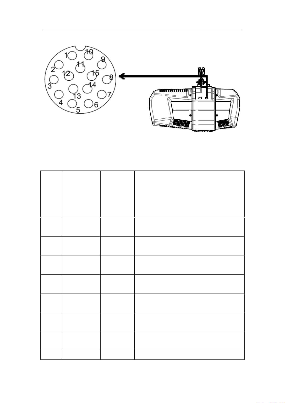
Intelligence Aided Lifting Equipment
Pin No.
IO
number
of
equipmen
t program
Signal
definition
Notes about pin definition
1
None
D24V
The public power output is 24 V and the maximum
current is 2,000mA.
2 4 INPUT
0
When the external input signal is 0, the low level is
valid.
3
5
INPUT 1
When the external input signal is 1, the low level is
valid.
4
6
INPUT 2
When the external input signal is 2, the low level is
valid.
5
7
INPUT 3
When the external input signal is 3, the low level is
valid.
6
8
INPUT 4
When the external input signal is 4, the low level is
valid.
7
9
INPUT 5
When the external input signal is 5, the low level is
valid.
8
10
INPUT 6
When the external input signal is 6, the low level is
Fig. 5. 1 Pin diagram of the host extension interface
The pin definition of the host extension interface of the equipment is shown in Table 5.Table
5
Table 5
45
Page 46
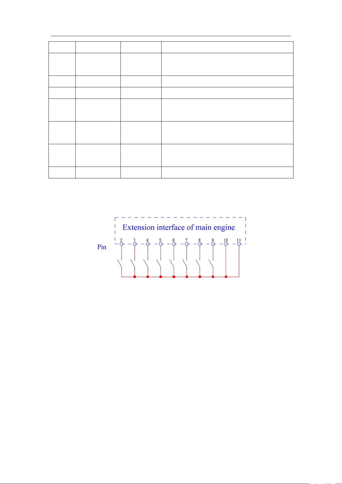
Intelligence Aided Lifting Equipment
valid.
9
11
NPUT 7
When the external input signal is 7, the low
level is valid.
10
None
GND
Power ground signals
11
None
GND
Power ground signals
12
Reserve
OUT0
If the Darlington Drive outputs signals by 0 route,
then the maximum current is 500mA.
13
Reserve
OUT1
If the Darlington Drive outputs signals by 1 route,
then the maximum current is 500mA.
14
Reserve
OUT2
If the Darlington Drive outputs signals by 2 route,
then the maximum current is 500mA.
15
Reserve
Reserve
Reserve
The external wiring method at the host extension interface is shown in Fig. 5. 2 The connection
diagram of the host extension interface.
Fig. 5. 2 The connection diagram of the host extension interface
5.7.2 Handle extension interface
The extension interfaces of coaxial handles (coaxial sliding handles or coaxial pressure
handles) and remote installation sliding handles provide CAN communication, RS232, 2 routes for
outputs and 4 routes for input signals. RS232 interface is mainly used for equipment debugging
and system software upgrade.
Taking the coaxial sliding handle as an example, the pin diagram at handle extension
interface is shown in Figure 5.Fig. 5. 3, color correspondence of 12-core handle extension cable to
that in handle extension port is shown in Figure 5.Fig. 5. 4.
46
Page 47
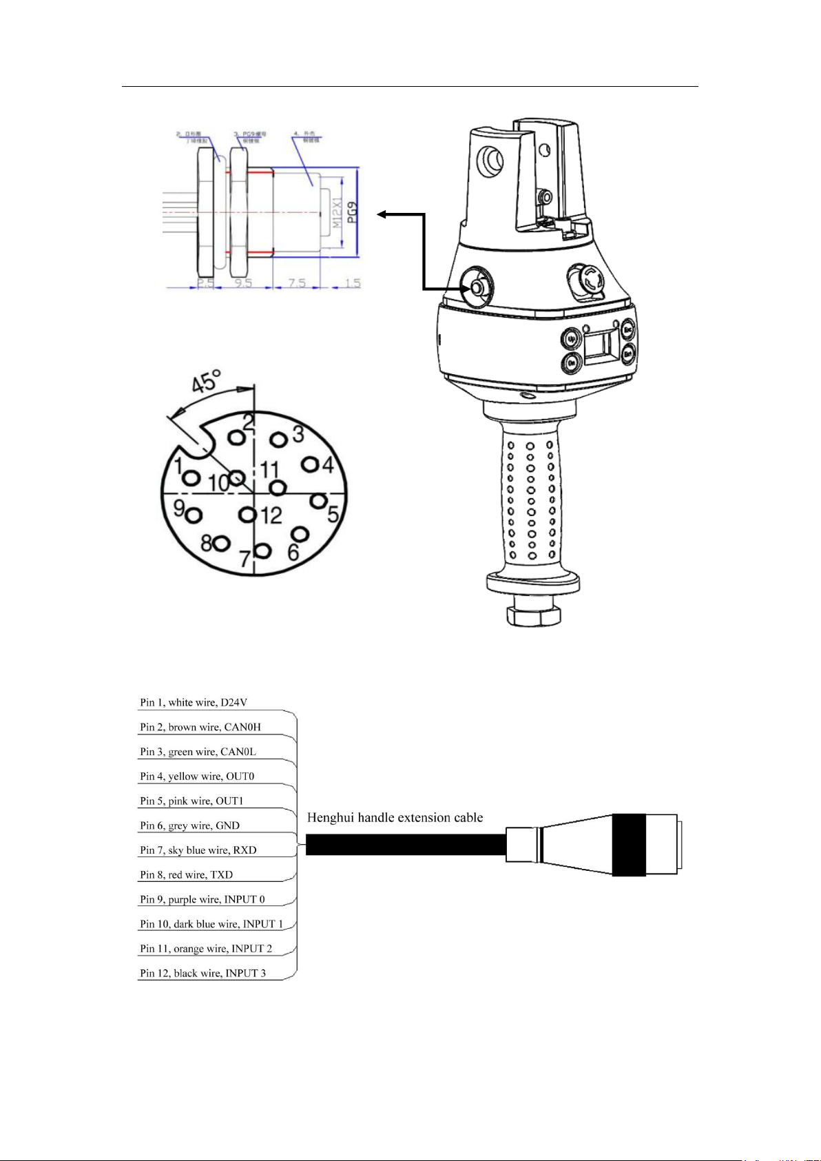
Intelligence Aided Lifting Equipment
Fig. 5. 3 The pin diagram of the coaxial handle extension interface
Fig. 5. 4
For the pin definition of the coaxial handle extension interface of the device, see table 6.
47
Page 48
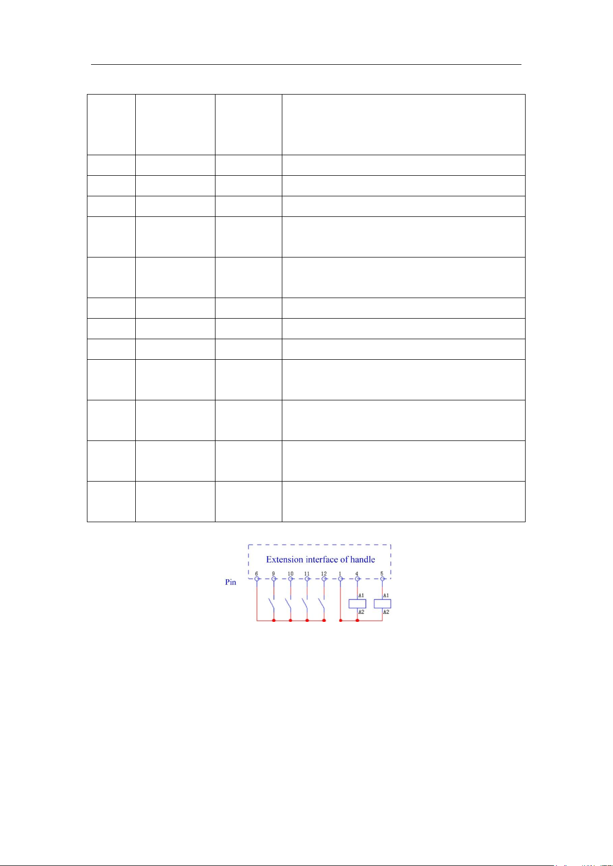
Table 6
Pin No.
IO number of
equipment
program
Signal
definition
Notes about pin definition
1
None
D24V
Public power output, with 500mA maximum current.
2
None
CAN0H
High signal of CAN communication
3
None
CAN0L
Low signal of CAN communication
4
24
OUT0
When the output of MOS cable is 0, the maximum
current output is 500mA.
5
25
OUT1
When the output of MOS cable is 1, the maximum
current output is 500mA.
6
None
GND
Publicly
7
None
RXD
Serial port RS232 receives signal.
8
None
TXD
Serial port RS232 sends signal.
9
12
INPUT 0
When the external input signal is 0, the low level is
valid.
10
13
INPUT 1
When the external input signal is 1, the low level is
valid.
11
14
INPUT 2
When the external input signal is 2, the low level is
valid.
12
15
INPUT 3
When the external input signal is 3, the low level is
valid.
Intelligence Aided Lifting Equipment
The external wiring method at the handle expansion port is shown in Fig. 5. 5
Fig. 5. 5 The connection diagram at the handle extension interface
The extension interfaces of indefinitely variable speeds handles and the all-touch handles
provide CAN communication, RS232, 2 routes for outputs and 2 routes for input signals. RS232
interface is mainly used for equipment debugging and system software upgrade. Taking the
indefinitely variable speeds handle as an example, the pin diagram at handle extension interface is
shown Figure 5. 6, and the color correspondence of 12-core handle extension cable to that in
handle extension interface is shown in Figure 5. 7.
48
Page 49
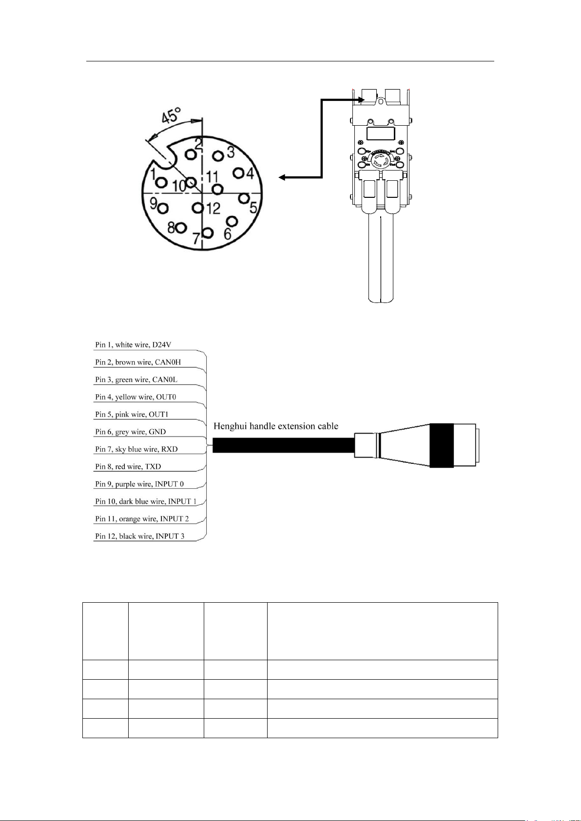
Intelligence Aided Lifting Equipment
Pin No.
IO number of
equipment
program
Signal
definition
Notes about pin definition
1
None
D24V
Public power output, with 500mA maximum current.
2
None
CAN0H
High signal of CAN communication
3
None
CAN0L
Low signal of CAN communication
4
24
OUT0
When the output of MOS cable is 0, the maximum
Figure 5. 6 Pin diagram of the indefinitely variable speeds handle extension interface
For the pin definition of the coaxial handle extension interface of the device, see table 6.
Table 7
Figure 5. 7 8
49
Page 50
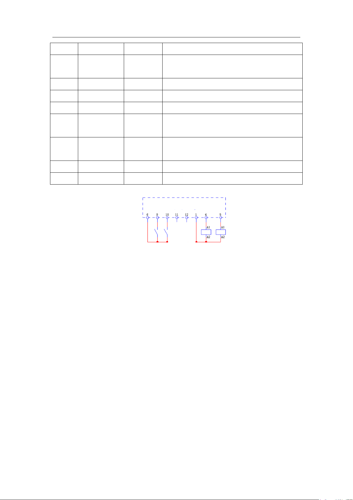
Intelligence Aided Lifting Equipment
current output is 500mA.
5
25
OUT1
When the output of MOS cable is 1, the maximum
current output is 500mA.
6
None
GND
Publicly
7
None
RXD
Serial port RS232 receives signal.
8
None
TXD
Serial port RS232 sends signal.
9
12
INPUT 0
When the external input signal is 0, the low level is
valid.
10
13
INPUT 1
When the external input signal is 1, the low level is
valid.
11
14
—
Undefined.
12
15
—
Undefined.
Extension interface of handle
Pin
The external wiring method at the handle extension interface is shown as follows:
Figure 5. 9 The connection diagram at the handle extension interface
5.9.3 External Expansion Board Interface
Intelligence aided lifting equipment provides extra external expansion board functions,
offering users more input/output interfaces. Each lifting equipment can at most match two
expansion boards. Each expansion board can provides extra 4-way input and 4-way output. The
extra 4-way output each expansion board provides is relay-type and can at most tolerate 1A of
electric current. The handle input end of expansion board 1 connects with the handle extension
interface and expansion board 2 directly connects with expansion board 1 through the extension
interface.
Some simple functions of PLC can also be achieved by expansion boards. See sections about
PLC expansion boards for details.
Prompt: The dial switch of expansion board 1 should be set as 1ON 2ON 3ON 4OFF
and the dial switch of expansion board 2 should be set as 1ON 2ON 3OFF 4ON, or these
expansion boards cannot work.
The expansion board has 1 handle input interface, 1 handle output interface, 1 extension
interface, 4 input interfaces and 4 output interfaces.
The handle input interface of each expansion board can be used as a connector between
expansion board and (coaxial/stepless) handle extension interface and can communicate through
50
Page 51
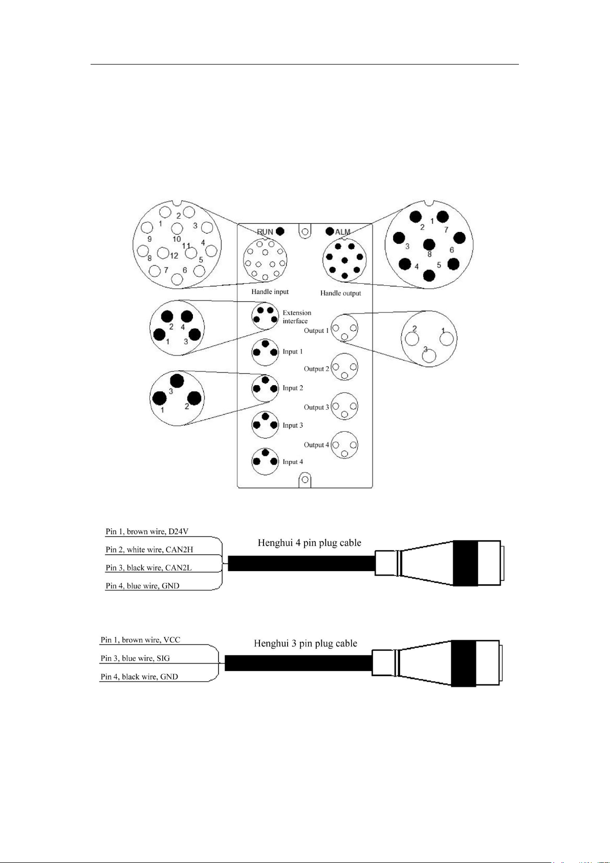
Intelligence Aided Lifting Equipment
CAN bus. The handle output of expansion board is a IO port directly leading to the handle so the
IO number of the handle output end of expansion board 1 should be consistent with that of handle
extension interface.
Expansion board 2 can communicate with expansion board 1 only through the extension
interface and CAN bus. The handle input and output interfaces of expansion board 2 are all
invalid.
Fig. 5. 10Expansion Board
Fig. 5. 11 Henghui 4-core plug cable (extended interface)
Fig. 5. 12 The definition of Henghui 3-core plug cable (input)
51
Page 52
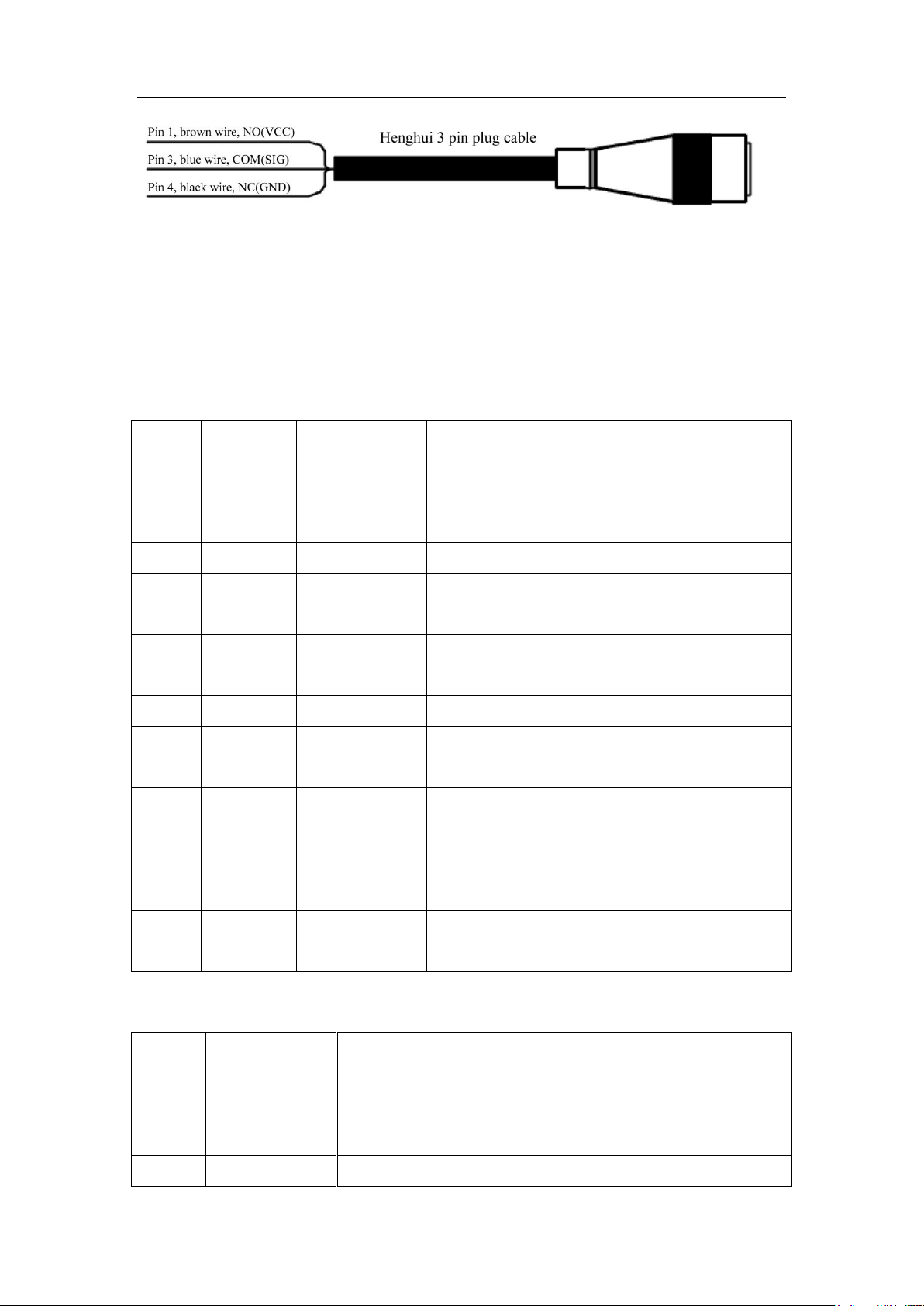
Intelligence Aided Lifting Equipment
Pin No.
IO number
of
equipment
program
Signal
definition
Notes about pin definition
1
None
D24V
Public power output, with 500mA maximum current.
2
24
OUT0
When the output of MOS cable is 0, the maximum
current output is 500mA.
3
25
OUT1
When the output of MOS cable is 1, the maximum
current output is 500mA.
4
None
GND
Publicly,
5
12
INPUT 0
When the external input signal is 0, the low level is
valid.
6
13
INPUT 1
When the external input signal is 1, the low level is
valid.
7
14
INPUT
2
When the external input signal is 2, the
low level is valid.
8
15
INPUT
3
When the external input signal is 3, the
low level is valid.
Pin No.
Signal
definition
Description
1
D24V
The public power output is 24V, the maximum current of
which is 500mA.
2
CAN2H
High signal of CAN communication.
Fig. 5. 13 The definition of Henghui 3-pin plug cable (output)
Note:
The handle input interface of each expansion board connects with the handle extension
interface through straight wires so the pin definition of extension interface on expansion
board should be consistent with that of handle extension interface.
For the pin definition of the handle output interface on expansion board, see Table .
Table 8
For the pin definition of the extension interface, see Table .
Table 9
52
Page 53
Intelligence Aided Lifting Equipment
3
CAN2L
Low signal of CAN communication.
4
GND
Publicly
Pin No.
Signal
definition
Description
1
VCC
The current of DC24V output is limited to 100mA.
2
SIG
For NPN signal input, the low level is valid.
3
GND
Publicly
Pin
No.
Signal
definition
Description
1
NO (VCC)
Normally closed contact of relay
2
COM (SIG)
Relay common port
3
NC (GND)
Normally open contact of relay
Sign
al
Expansi
on
board 1
IO number of
equipment program
Expansion board 2
IO number of
equipment program
Input
signa
l
Input 1
Chapter I 16
Chapter II Input
1
Chapter III 20
Input 2
17
Input 2
21
Input 3
18
Input 3
22
Input 4
19
Input 4
23
Outp
ut
signa
l
Output 1
28
Output 1
32
Output 2
29
Output 2
33
Output 3
27
Output 3
31
Output 4
30
Output 4
34
Definition of input/output interfaces on expansion boards and IO number
The pin definition of input port is shown in Table .
Table 10
For the pin definition of the output interface, see Table 11.
Table 11
For program number of input/output interfaces, see Table 12.
Table 12
53
Page 54

Intelligence Aided Lifting Equipment
Chapter VI Menu setting
6.1 Overview
The menu is used to adjust and control all functions of the intelligent aided lifting device.
Before performing menu operations, please comprehend the related menu functions.
6.1.1 Operation mode
1. Press the “ENT” button to enter the main menu interface.
2. Press the “Up” and “Down” buttons to switch among various menus, which would be
displayed correspondingly on LCD:
Software limit
Lifting speed regulation
Weighing setting
Setting of suspension
Setting of overload
Time-out setting
Count
Service
Extended function setting
Palletizing function setting
l touch setting / coaxial pressure setting (displayed with all - touch handles or coaxial
pressure handles)
3. After entering the menu, press the “ENT” button to enter the submenu.
4. Choose and set the required function, and press the “ENT” button to save the setting.
5. If the chosen menu is wrong, press the “ESC” button to exit and re-choose menu.
6. After completing menu settings, press the “ESC” button to return to the main interface.
Note:
The digits may be switched among the units, tens... by pressing the “Up” or “Down” button
for seconds, achieving a rapid setting.
During the menu setting process, make sure your fingers do not cover the sensing area of the
infrared sensor, or otherwise, the menu settings will be automatically interrupted. In this case, you
need to re-enter the menu for setting.
54
Page 55
Intelligence Aided Lifting Equipment
Menu
Function
Function description
Soft limit
setting
Soft limit 1
Set the parameters in software limit 1.
Soft limit 2
Set the parameters in software limit 2.
Soft limits
switching
Set the parameters of soft limit 1 and soft limit 2 to
effective mode. (Chapter 4.4)
Soft limit 1
Upper software
limit
Set the upper software limit point to make the equipment
stop operation when ascending to the point.
Lower software
limit
Set the lower software limit point to make the equipment
stop operation when descending to the point.
Downward
slowdown point
Set the downward slowdown point to make the
equipment start slowing down when descending to the
point.
Upward slowdown
point
Set the upward slowdown point to make the equipment
start slowing down when ascending to the point.
Upward speed-up
point
Set the upward speed-up point to make the equipment
start recovering its speed when ascending to the point (it
is only effective to set this point higher than the upward
slowdown point).
Reset soft limit
Reset all soft limits set in this menu to “Invalid”.
Soft limit 2
Upper software
limit
Set the upper software limit point to make the equipment
stop operation when ascending to the point.
Lower software
limit
Set the lower software limit point to make the equipment
stop operation when descending to the point.
Downward
slowdown point
Set the downward slowdown point to make the
equipment start slowing down when descending to the
point.
Upward slowdown
point
Set the upward slowdown point to make the equipment
start slowing down when ascending to the point.
Upward speed-up
point
Set the upward speed-up point to make the load start
recovering its speed when ascending to the point (it is
only effective to set this point higher than the upward
6.2 Description of menu functions
The function instruction for intelligent aided lifting equipment is shown in Table 13.
Table 13
55
Page 56
Intelligence Aided Lifting Equipment
slowdown point).
Reset soft limit
Reset all soft limits set in this menu to “Invalid”.
Lifting speed
regulation
Speed setting
Set the maximum running speed of the handle speed,
suspension speed, unloading speed and homing speed.
Inching speed
setting
Set the running speed of the fast gear /slow gear of
inching function in the extended function.
Lifting sensitivity
Set the acceleration in the suspension mode, with [1-5]
corresponding to the minimum and the maximum
acceleration respectively.
No-load speed
setting
Enter into no-load deceleration function submenu
Speed setting
(submenu)
Handle speed
setting
Select the maximum running speed in the mode of
manual hold of equipment, with [1-10] corresponding to
the minimum and the maximum speed respectively.
Suspension speed
setting
Select the maximum running speed in the suspension
mode of equipment, with [1-10] corresponding to the
minimum and the maximum speed respectively.
Unloading speed
setting
Select the maximum running speed in the unloading
mode of equipment, with [1-10] corresponding to the
minimum and the maximum speed respectively.
Homing speed
setting
Select the maximum running speed under the homing
function of equipment, with [1-10] corresponding to the
minimum and the maximum speed respectively.
No-load speed
setting
(Submenu)
No-load speed
switch
Set the turning-on/turning-off of no-load deceleration
function;
No-load weight
threshold
The weight value based on which whether the setting of
no-load slowdown function is valid is judged.
No-load speed
adjustment
Speed gear used to set no-load deceleration.
No-load speed time
limit
Deceleration time when setting no-load deceleration.
Weighing
setting
Weight zero
position
Set the current weight value to “Zero”, which is similar
to the tare function.
The setting of the weight zero position is effective when
the actual weight is less than 60KG.
56
Page 57

Intelligence Aided Lifting Equipment
Whether to display
the weight
Set the main interface, confirm whether it display the
weight value of the load.
Setting of
suspension
Anti-rebound mode
Switch the anti-rebound testing mode between
over-speed and over-load.
Anti-rebound function: When the load weight of
equipment in the suspension mode reduces, it will be
avoided that the hook moves upwards and collides with
an object or push the equipment resulting in dropping
down of the load.
Detection of overspeed: When the operating speed of the
load reaches 90% of the maximum speed in the
suspension mode, the operation will stop, and LCD will
display “overspeed alarm”.
Detection of overload: If the operating force exerted on
the load by users exceeds the “Max. Over-power” (either
upper limit or lower limit), the operation will terminate,
and the LCD will show “overload alarm”. Other than the
over-speed testing, the equipment may operate at the
maximum speed in the suspension mode.
Default max. Over-power is 10KG.
Where the total lifting weight (such as tools and parts) is
less than the maximum limit, the over-speed testing
should be made.
Over-power test is default.
Max. over-power
Set the maximum anti-rebound over-power (2-20 kg),
classified into upward over-power and downward
over-power.
Automatic
suspension
Enter into the automatic suspension mode.
Maximum speed
operating force
The force required to reach the maximum speed in the
suspension mode = maximum speed operating force +
operating over-power threshold value The setting range
is [3-10KG]. When the suspension function is in normal
state, the lower the value is set, the less force is required
to reach the maximum speed in the suspension mode.
57
Page 58

Intelligence Aided Lifting Equipment
Note: the stability of the suspension function may be
affected if the set value is too low.
Function switch of
suspension
Allow or prohibit operating relevant functions of
suspension mode.
Automatic
suspension
(submenu)
Whether turned on
Select the turning-on/turning-off of automatic suspension
mode.
Detection time
Time condition under which the entering into the
automatic suspension mode is made possible. When the
load meets the weighting condition, the system will
automatically enter into the suspension mode if the
continuous duration reaches the time period set before.
Detection weight
Weighting condition under which the entering into the
automatic suspension mode is made possible. When the
current weight value meets (set value of detection weight
- operating over-power threshold value + 0.5KG <
current weight value < set value of detection weight +
operating over-power threshold value), the system will
begin timekeeping with regards to the “detection time”.
(Give no more than 10 sets of detection weight range)
Setting of
overload
Overload threshold
value
Set an overload threshold value. When the weight value
of the load exceeds the set overload threshold value, the
system will raise an “overload alarm”, during which
period of time, the equipment is unable to lift the load
upwards, but can lower it. The setting range is
[10KG-110% of rated loading capacity]
The load weight which causes the system to enter into
“overload alarm” >= overload threshold value +
operating over-power threshold value.
When the system enters into the “overload alarm”
condition:
If the load weight value < (overload threshold value +
operating over-power threshold value) * 150%, then the
equipment can run downward but cannot run upward.
If the load weight value ≥ (overload threshold value +
operating over-power threshold value) * 150%, then the
58
Page 59

Intelligence Aided Lifting Equipment
equipment cannot run.
Operating
over-power
threshold value
For system, pushing or pulling force of operator is an
extra load. This menu sets a limit value of operating
overload for users to reduce the possibility of
error-reporting detection of overload. The limit value
shall not be too big, and otherwise it will reduce the
overload detection capability. The operating over-power
threshold value is between 2 and 11KG.
Overload
sensitivity
Attention! The test on the varied weight may go wrong
due to the overload as thought. (Example: In the system,
lifting imbalanced or slender tools will easily cause
swing, or excessive vibration will be induced if not using
rigid support structure. When the load in operation does
not reach the limit value of overload, adjust the
sensitivity parameters to reduce protective error
detection. However, in actual application, if not
necessary, there is no need to reduce the sensitivity. Low
sensitivity extends the time taken to test normal
overloads, which can easily cause the damage to
equipment or report errors.
The detection sensitivity is between 1 (low) and 5 (high).
Time-out
setting
Manual time-out
value
Set a manual time-out value (1-59s).
Time-out value of
suspension
Set a time-out value (1-5min) of suspension. Such setting
will have no impact on the automatic suspension mode.
Count
Upper limit
position counting
Record the number of times equipment has passed the
count point at the upper limit position.
Lower limit
position counting
Record the number of times equipment has passed the
count point at the lower limit position.
Circulation
counting
Record the cycle times of equipment.
Running time
Display the total running time of equipment (unit: H),
where the running time is defined as the total period of
time when the equipment is switched on.
Service
Zero position
Set the current position as zero position (effective after
59
Page 60
Intelligence Aided Lifting Equipment
restarting).
Upper limit of
circulation
counting
Edit the position of the count point at the upper limit
position for circulation counting.
Lower limit of
circulation
counting
Edit the position of the count point at the lower limit
position for circulation counting.
Zero clearing of
circulation
counting
Reset the circulation counting as zero (including “upper
limit position counting”, “lower limit position counting”
and “circulation counting” on the “counting” menu).
Zero clearing of
running time
Clear the running time in the “counting” to be zero and
the running time will begin timekeeping again.
Prompt for
maintenance
resetting
When the maintenance running time of equipment
reaches the set value in the system, the system will
remind users to carry out the maintenance. After users
have finished the maintenance, click the resetting and the
maintenance running time will be cleared to be zero,
beginning timekeeping once again.
Model
Display the model of the current intelligence aided lifting
equipment.
Temperature
Display the temperature of the current servo brake
resistor.
Version No.
Display the software versions of handle and main
control.
Hardware
diagnostic
Click to enter the hardware diagnostic submenu.
Calibrate the
handle holder
Adjust the zero position of handle holder. Calibrate the
handle in case of the display of “abnormal handle
holder”.
Wireless switch
Turn the wireless remote control function on/off.
Password
protection
Set the turning-off/turning-on of password protection.
Steel wire rope
lockout threshold
Set the steel wire rope lockout threshold. If the load
weight value is greater than the set value, then there will
be an alarm that the steel wire rope is loose when the
60
Page 61
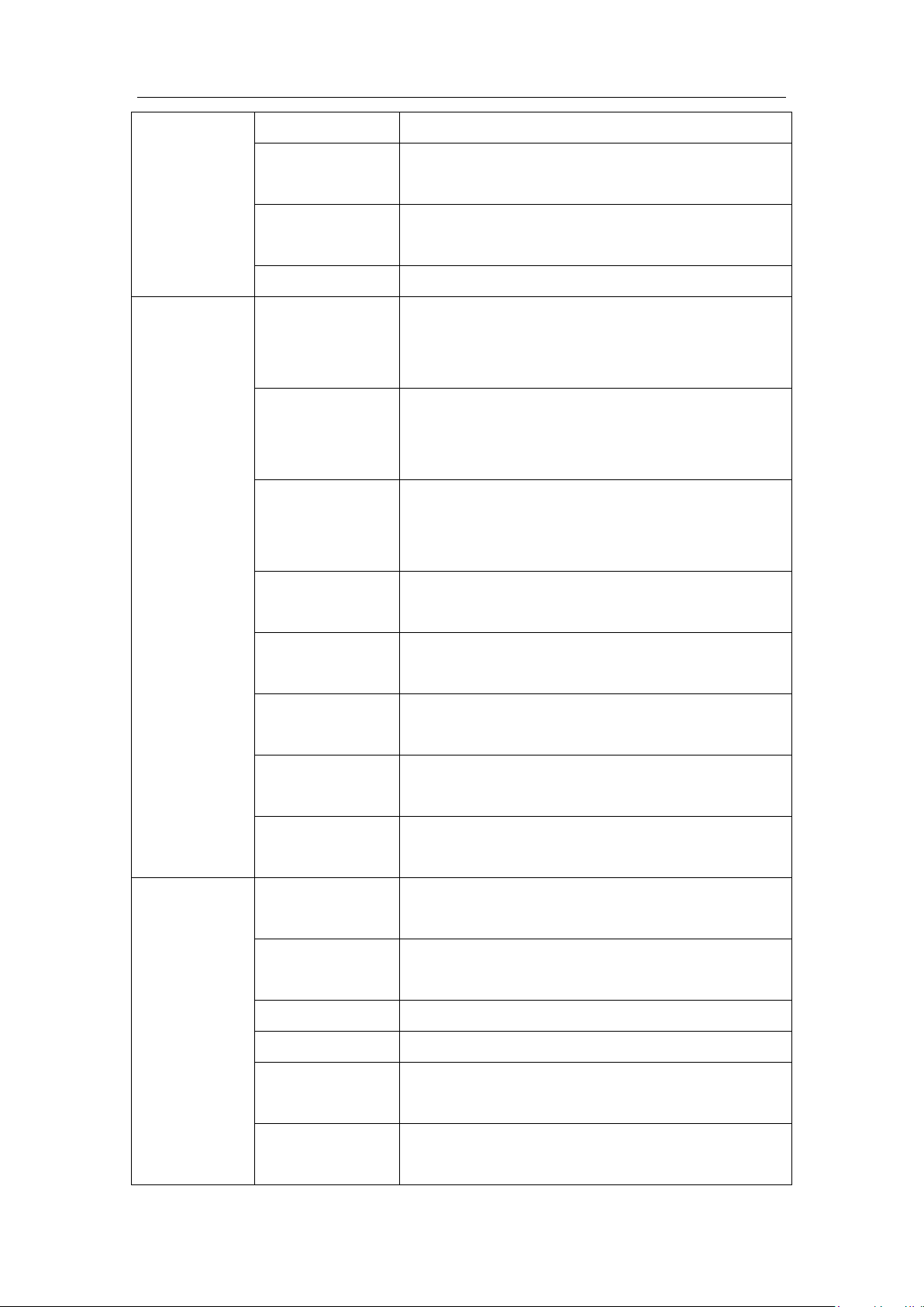
Intelligence Aided Lifting Equipment
equipment moves downward.
Password change
Set user password, with the initial password being
123456.
Multi-language
switch
Select the language on the user interface among Chinese,
English and French.
PLC switch
Turn on the PLC function.
(Submenu)
Hardware
diagnostic
Diagnosis of
handle board
extended port
Input and output signal test for the handle extended port,
for maintenance personnel.
Diagnosis of main
board extended
port
Input and output signal test for the main board extended
port, for maintenance personnel.
Diagnosis of
expansion board
extended port
Input and output signal test for the expansion board
extended port, for maintenance personnel.
Handle gripping
signal
When the infrared sensor detects an operator, the handle
gripping signal will change from “off” to “on”.
Fan diagnosis
Check whether the cooling fan of the main engine is in
normal state.
Upper limit signal
of hardware
When the equipment arrives at the upper limit of
hardware, the signal will change from “off” to “on”.
Lower limit signal
of hardware
When the equipment arrives at the lower limit of
hardware, the signal will change from “off” to “on”.
Signal of loose
steel wire rope
When any loose steel wire rope is tested by the system,
the signal will change from “off” to “on”.
Extended
function setting
Extended port
setting
Click to enter into extended port function setting.
Double suspension
setting
Click to enter into double suspension setting menu.
Anti-drop setting
Click to enter into anti-drop setting menu.
Homing setting
Click to enter into homing setting menu.
Switch of weight
interface
Turns the weight data transmission interface on/off.
Frequency of
weight interface
Set the frequency of the weight data transmission
interface.
61
Page 62
Intelligence Aided Lifting Equipment
(submenu)
Extended port
setting
(extended
function)
Slow gear
downwards
Set the IO No. of slow gear downwards (0 means
invalid), and the signal shall be input signal.
Slow gear upwards
Set the IO No. of slow gear upwards (0 means invalid),
and the signal shall be input signal.
Fast gear
downwards
Set the IO No. of fast gear downwards (0 means invalid),
and the signal shall be input signal.
Fast gear upwards
Set the IO No. of fast gear upwards (0 means invalid),
and the signal shall be input signal.
Switch to
suspension
Set the IO No. of switch to suspension (0 means invalid),
and the signal shall be input signal.
Switch to
suspension
unloading
Set the IO No. of switch to suspension unloading (0
means invalid), and the signal shall be input signal.
Switch to double
limit
Set the IO No. of double limit (0 means invalid), and the
signal shall be input signal.
Switch to double
suspension 1
Set the IO No. of switch to double suspension (0 means
invalid), and the signal shall be input signal.
Switch to double
suspension 2
Set the IO No. of switch to double suspension (0 means
invalid), and the signal shall be input signal.
Auto homing
Set the IO No. of automatic homing (0 means invalid),
and the signal shall be input signal.
Clamping signal
input
Set the IO No. of clamping signal input (0 means
invalid), and the signal shall be input signal.
Loosening signal
output
Set the IO No. of loosening signal input (0 means
invalid), and the signal shall be input signal.
Clamping signal
feedback
Set the IO No. of clamping signal feedback (0 means
invalid), and the signal shall be input signal.
Loosening signal
feedback
Set the IO No. of loosening signal feedback (0 means
invalid), and the signal shall be input signal.
Clamping signal
output
Set the IO No. of clamping signal output (0 means
invalid), and the signal shall be output signal.
Loosening signal
output
Set the IO No. of loosening signal output (0 means
invalid), and the signal shall be output signal.
Stacking signal
input
Set the IO No. of stacking signal output (0 means
invalid), and the signal shall be input signal.
62
Page 63
Intelligence Aided Lifting Equipment
All – touch safety
signal
Set the IO number (0 is invalid) of the safety signal of all
– touch handles, which is the input signal.
During usage process, if the input signal is available,
then users can operate a all-touch handle to control the
equipment to run upwards and downwards, but if input
signal is not available, then the all-touch handle cannot
be used to control the equipment.
(Submenu)
Double
suspension
setting
(extended
function)
The double suspension function allows the equipment to remain in suspension
mode at all times, allowing the suspended load to be switched between fixture
weight and the weight of fixture + work piece.
Fixture weight
Set fixture weight within the range of [0-60] KG.
Fixture workpiece
weight
Set fixture workpiece weight.
Double suspension
mode
Set double suspension mode, classified into automatic
and manual
Detection time
Set the detection time required to enter the double
suspended state in automatic double suspension mode.
Signal selection
Set the switching mode of double suspension, classified
into single signal, double signals and fixture signal.
Double suspension
protection
Enter into the protection submenu under double
suspension (effective for single signal and double
signals)
(submenu)
double
suspension
suspension
protection
(extended
function)
This function can prevent the double suspension from falsely triggering the
double suspension switching signal in the non-grabbing and unloading
positions.
Protection switch
Turn on or off the protection function.
Unloading high
position
Set the highest position of unloading point.
Unloading low
position
Set the lowest position of unloading point.
Grasping high
position
Set the highest position of grasping point.
Grasping low
position
Set the lowest position of grasping point.
(Submenu)
The anti-drop function can prevent users from accidentally pressing the fixture
63
Page 64
Intelligence Aided Lifting Equipment
Anti-drop
setting
(extended
function)
release button while moving a heavy object, causing the heavy object to fall,
and causing damage to the equipment or personnel.
Anti-drop
threshold value
Set the anti-drop threshold value
(Submenu)
Homing setting
(extended
function)
Homing location
Set the homing location point.
Homing weight
Set the load weight which causes homing.
Palletizing
function setting
Stacking function
switch
Select the turning-on/turning-off of stacking function.
Layer height
resetting
Reset the position data stored from Layer 1 to Layer 20
as “invalid”.
Layer
Set the position value of each layer. (Maximum 20
layers)
All-touch
handle
(all-touch
handles only)
Maximum speed
operating force
When the equipment reaches the maximum speed, the
force value at the all-touch handle end shall be exerted.
Enable operating
force value
When the equipment begins to move, the force value at
the all-touch handle end shall be exerted.
Lifting sensitivity
The acceleration of mode of manual hold under the
all-touch handle.
Handle zero point
value
The value of pressure sensor when the handle is
vertically still.
Coaxial
pressure handle
(coaxial
pressure
handles only)
Maximum speed
operating force
When the equipment reaches the maximum speed, the
force value at the all-touch handle end shall be exerted.
Enable operating
force value
When the equipment begins to move, the force value at
the all-touch handle end shall be exerted.
Lifting sensitivity
The acceleration of mode of manual hold under the
all-touch handle.
Handle zero point
value
The value of pressure sensor when the handle is
vertically still.
64
Page 65

Intelligence Aided Lifting Equipment
Failure
Causes of failure
Remedy
No display for
handle LCD
1. 24V power supply is
not supplied to the
handle end;
2. The internal sliding
connection of the
handle, the cables or
the handle board are
abnormal;
Check whether the main unit input power
supply wiring is normal [Chapter 3.1].
Check whether the main unit input supply
voltage is normal. Single wire 220VAC for
80KG and 200KG, three-phase 220VAC for
300KG and 600KG. [Chapter 3.1]
Check whether the signal cable is connected to
the handle end with 24V power supply: for
coaxial handles, indefinitely variable speeds
handles and all – touch handles, please check
Pin 1 and Pin 4; for remote installation sliding
handles, please check Pin 2 and Pin 6. [Chapter
2.5]
Check whether the voltage of Pin 1 and Pin 4 of
the host signal cable interface is 24V. [Chapter
3.2]
Check whether there is 24V output at the
switching power supply in the machine.
Check whether the main circuit board connector
in the machine is loose.
Check whether the power supply of the Pin
24V_IN and the Pin COM at the “Handle
Control Interface” of the main circuit board in
the machine is 24V.
Check the handle slipping rings and internal
connecting cables.
Chapter VII Maintenance
7.1 Inspection & Maintenance Timetable
For the maintenance timetable for intelligence aided lifting equipment, please refer to
Maintenance Manual.
7.2 Basic failure diagnosis
65
Page 66

Intelligence Aided Lifting Equipment
The handle always
shows “Emergency
Stop Mode”
1. Caused by the
emergency stop switch
itself;
2. The emergency stop
signal cable is
blocked;
3. There is a problem
with the handle or the
main circuit board.
Make sure the emergency stop button pops up
normally.
Check whether the emergency stop signal cable
of the signal cables is normally turned on: for
indefinitely variable speeds handles, coaxial
handles, all – touch handles and remote
installation sliding handles, please check the Pin
5 of handle end connector and the Pin 5 of host
end. [Chapter 2.5]
Check whether the internal cable
WI-830000014 of the host is normally turned
on.
Check the handle slipping rings and internal
connecting cables.
Replace the main circuit board.
The equipment is
always in “Lock
Mode”
1. For sliding handles
and coaxial pressure
handles: the infrared
sensor cannot sense
properly;
2. For indefinitely
variable speeds
handles and all – touch
handles: the sensor or
the handle board is
abnormal.
For sliding handles and coaxial pressure
handles: check that the infrared sensor is
normally on/off in the “Service” > “Hardware
Diagnostics” > “Handle Holder Signal” menu.
If the infrared sensor is normally on: clean the
infrared sensor probe and the perimeter to
ensure that there is no object interference under
the handle. [Chapter 4.1.2]
If the infrared sensor is normally off: check if
the infrared sensor connector inside the handle
is loose and replace the infrared sensor or
handle board.
For indefinitely variable speeds handles: press
the “UP” and “Down” button in the “Service” >
“Handle Holder Calibration”, and the value will
change from the correct value (less than ±150)
to the wrong value (around ±1800).
If the value does not change: check if the
magnet in the magnetic cylinder is off, and
replace the sensor board and the handle board.
66
Page 67

Intelligence Aided Lifting Equipment
For all – touch handles: operate the control area
under the “All – touch Handle” > “Handle Zero
Point Value” menu, then there will be hundreds
of variations in the menu.
If the value does not change: check the internal
pressure sensor, and replace the sensor and the
handle board.
The equipment
cannot move
upwards or
downwards
1. The equipment
cannot enter the
“Handle Gripping
Mode” or “Suspension
Mode”;
2. The position is at
the limit or the
equipment has an
alarm.
Check whether the handle is in the “Handle
Gripping Mode” or “Suspension Mode”;
Check if the current position is in the hardware
upper limit or hardware lower limit position.
Check if the current position is in the software
upper limit or software lower limit.
Check whether there is an alarm in the handle
display.
Check whether the internal drive of the host
displays an alarm code Al.xxx. The alarm
handling method is described below.
The lifting speed of
equipment is low
1. Caused by
parameter setting;
2. The handle zero
point value is offset;
3. Caused by program
built-in functions.
Check if the set speed in the “Lifting Speed
Setting” > “Speed Setting” menu is too low.
Check whether the “Lifting Speed Setting” >
“No-load Speed Setting” menu is in the “Open”
state. If it is open, then the upward running
speed will be too small.
Check the slowdown point setting in the soft
limit menu;
Check whether it is within 10cm before the
hardware limit; if yes, then it is normal.
The higher the lifting capability of equipment is,
the lower the value of lifting speed is. The
lifting speed of 600KG and 300KG is lower
than that of 200KG and 80KG (under the same
speed gear). For specific lifting speed, refer to
the Basic Parameter List;
Calibrate the handle zero point value as
67
Page 68

Intelligence Aided Lifting Equipment
described in 7.3 Handle Holder Calibration.
The equipment can
move downwards
only
1. Caused by
parameter setting;
2. The load weight
exceeds the rated
lifting capacity of the
equipment;
3. Caused by the
sensor.
Check the setting of the upper limit in the
software limit menu.
Check whether it is in the hardware upper limit
position.
Check whether it is in overload status.
Check whether the value will change
significantly (from correct to incorrect) when
operating the handle to move downwards from
the central position in emergency stop mode in
“Service” > “Handle Holder Calibration” menu.
Significant change means the analog quantity
sensor is normal.
The equipment can
move upwards only
1. Caused by
parameter setting;
2. Caused by hardware
limit;
3. Caused by the
sensor.
Check the setting of the lower limit in the
software limit menu.
Check the menu “Service” > “Hardware
Diagnostics” > “Steel Wire Rope Loose Signal”
is “on”. When it is “on”, the equipment cannot
be operated downward due to program
protection.
Check whether it is in the hardware lower limit
position;
Check whether the value will change
significantly (from correct to incorrect) when
operating the handle to move downwards from
the central position in emergency stop mode in
“Service” > “Handle Holder Calibration” menu.
Significant change means the analog quantity
sensor is normal.
The suspension
function cannot work
normally
1. Caused by
parameter setting;
2. The way to enter the
suspension mode is
wrong.
Check whether the equipment is working
properly in the handle gripping mode.
Check whether the “Suspension Function” >
“Suspension Function Switch” menu is in “On”
status.
Check whether the main interface is in
68
Page 69

Intelligence Aided Lifting Equipment
“Suspension Mode”.
Check whether additional force is applied to the
equipment during startup or if the equipment is
subject to severe sloshing.
Check whether the weighing data increase and
decrease value is standard. If it is not standard,
replace the main board or load cell.
Check whether the setting of “Suspension
Function” →“Max. Over-power” is too low;
Displaying
“Abnormal
Communication
Alarm”
1. The communication
cable is abnormal;
2. The servo RS485 is
abnormal.
1. Determine whether the time required from the
power-on to the “Abnormal Communication
Alarm!” is about 1min or about 10S.
If the time is about 1 min: then this failure is
caused by the abnormal communication
between the servo driver and the main board.
Check the communication cable
WI-830000022RS485; replace the main board;
and replace the servo.
If the time is about 10S: then this failure is
caused by the abnormal communication
between the host and the handle. Check the
connecting cable from the host to the handle.
For coaxial sliding handles, indefinitely variable
speeds handles and all – touch handles, please
check whether the Pin 2 and Pin 3 at the each
end of the cable between the host and the handle
are turned on and short-circuited. For remote
installation sliding handles, please check
whether the Pin 2 and Pin 3 at the end of the
host cable and the Pin 1 and Pin 7 at the end of
the handle cable are turned on and whether
these two cables are short-circuited. Check the
connecting cable WI-830000014 in the host and
the handle slipping ring. Replace the handle.
Handle displaying
1. The communication
The time required from the power-on to the
69
Page 70

Intelligence Aided Lifting Equipment
“faulty parameter
reading” alarm
cable is abnormal.
“Faulty Parameter Reading” alarm is about 10S,
and this phenomenon will not appear during the
operation of the equipment. The problem is
handled in the same way as the “Faulty Encoder
Reading”, where such time is also about 10S.
The running
indicator light is
always on or off.
1. The software
program crashes.
Crash of software programs can generally be
resolved by rebooting the equipment.
displaying “Software
Limit Alarm”
1. Caused by
parameter setting.
Caused by the setting of software upper limit or
software lower limit.
Reset the software upper limit or software lower
limit to invalid in software limits 1, 2.
Displaying
“Overload Alarm”
1. Caused by
mechanical parts;
2. Caused by
parameters or load;
Check whether the setting value in the
“Overload Setting” > “Overload Threshold”
menu is too small.
Check whether the load exceeds the rated
capacity of the equipment.
Check whether the internal steel wire rope is
broken or is sticking the equipment. Turn it
around once and observe.
Check whether the steel wire rope is stuck by
external objects.
Abnormal sound of
equipment
Check whether the steel cable is damaged. Turn
it around once and observe.
Check for loose screws or structural damage at
the cart or equipment junction.
Check whether there is foreign matter inside the
host.
Handle displaying
“Over Speed Alarm”
Caused by the reason that the parameters are not
imported after the main board has been
replaced. Please contact the manufacturer.
Handle displaying
“servo alarm ALxxx”
1. This failure shall be
judged based on the
type of servo alarm.
The column on the
Servo alarm AL060: The absolute position is
lost which is commonly caused by battery
undervoltage.
Processing method: 1. Replace the servo driver
70
Page 71

right only explains the
basic processing of
common problems.
For details, see servo
driver instruction
book.
The servo driver used
in the equipment is the
Delta ASDA-A2 series
high-performance
communication servo
driver.
battery. [Chapter 7.2.1]
Servo alarm AL061: The voltage of the
encoder is too low.
Processing method: 1. Replace the servo driver
battery. [Chapter 7.2.1]
Servo alarm AL003: Low voltage.
Processing method: 1. Check if the input
voltage is normal.
Servo alarm AL002: Over voltage.
Processing method: 1. Check if the input
voltage is normal.
Servo alarm AL006/AL009: Overload/position
error is too large.
Processing method: 1. Check if the servo power
cable connector is loose. 2. Check if the internal
steel wire rope servo of the host is stuck.
Servo alarm AL022: The main loop power
supply is abnormal.
Processing method: 1. Check if there is a phase
loss in the input power supply.
Servo alarm AL000: The alarm is not read.
Processing method: 1. For equipment with a
lifting capacity of 80KG or 200KG, please
restart the equipment to view the specific alarm
code. Open the front cover to view the real
alarm code. 2. For equipment with a lifting
capacity of 300KG, 600KG, if the equipment
still displays the AL000 alarm after restart, then
check whether there is a phase loss in the input
power supply. Open the front cover to view the
real alarm code.
Servo alarm AL06A: The absolute value has
not been initialized, and this alarm may appear
after the replacement of battery or motor.
Initialization steps:
Intelligence Aided Lifting Equipment
71
Page 72

Intelligence Aided Lifting Equipment
1. Open the servo parameter setting cover and
press the “MODE” button until the servo driver
interface displays P0-00.
2. Press the “SHIFT” button until the servo
driver interface displays P2-00.
3. Press the “▲” button until the servo driver
interface displays P2-08. Press the “SET” button
until the servo driver interface displays 00000.
Press the “▲” button to adjust the value to
00271, then click the “SET” button again.
4. Wait a few seconds until the interface returns
to P2-08. Press the “▲” button until the servo
driver interface displays P2-71. Press the “SET”
button until the servo driver interface displays
00000. Press the “▲” button to adjust the value
to 0001, then click the “SET” button again.
5. Wait a few seconds and restart the power
supply of the equipment.
If the equipment still displays that alarm, then
contact the manufacturer for processing.
7.3 Servo driver battery replacement
When the servo driver raises the alarm that the voltage of AL061 battery is too low, please
replace it with new battery immediately to avoid data loss. (The manufacturer recommends the
replacement when the equipment is used for one year) Please replace the battery while the drive is
powered.
7.3.1 Operation steps
1. Remove the front cover.
2. Find the battery box and open its cover.
3. Disassemble the battery connector, take the old battery out and install the new and cover.
Prompt: Please contact the manufacturer in case of any abnormity after the replacement.
7.4 Calibrate the handle holder
1. The equipment will move upon the triggering of the operator’s in-place sensor, so that
the handle holder is required to be calibrated. The calibration steps are as follows:
2. Select the “service” and “calibrate the handle holder” from the selection menu in the
72
Page 73
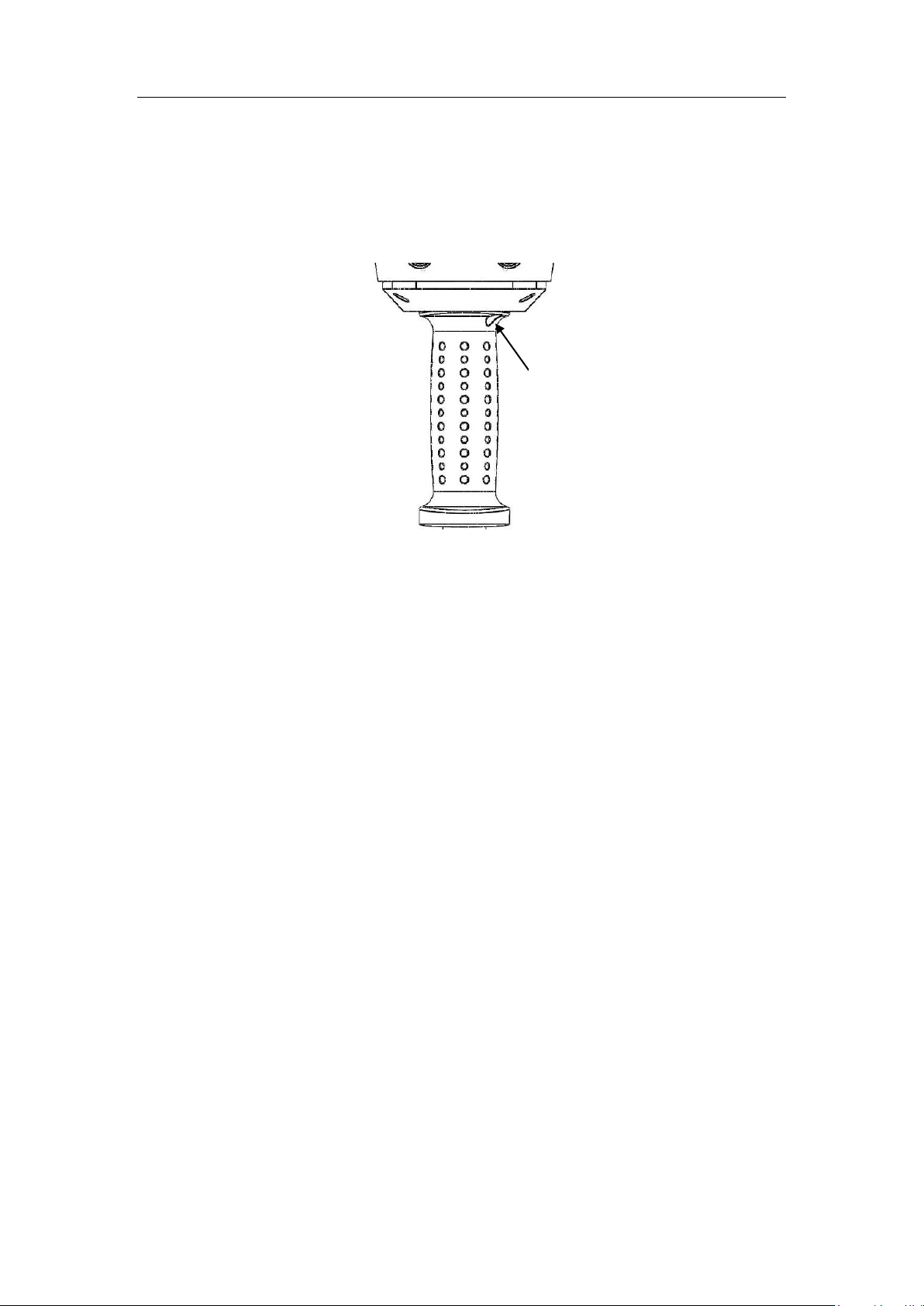
Intelligence Aided Lifting Equipment
Fig. 7. 1 Iron core position
Iron core bolt
emergency stop mode.
3. The allen wrench shall be inserted into where the arrow shows inFig. 7. 1.
4. Rotate anticlockwise or clockwise to respectively increase or reduce the parameters.
5. Adjust the value in the “correct” (-150 - +150) interval (when no external force is
exerted on the sliding handle).
73
Page 74
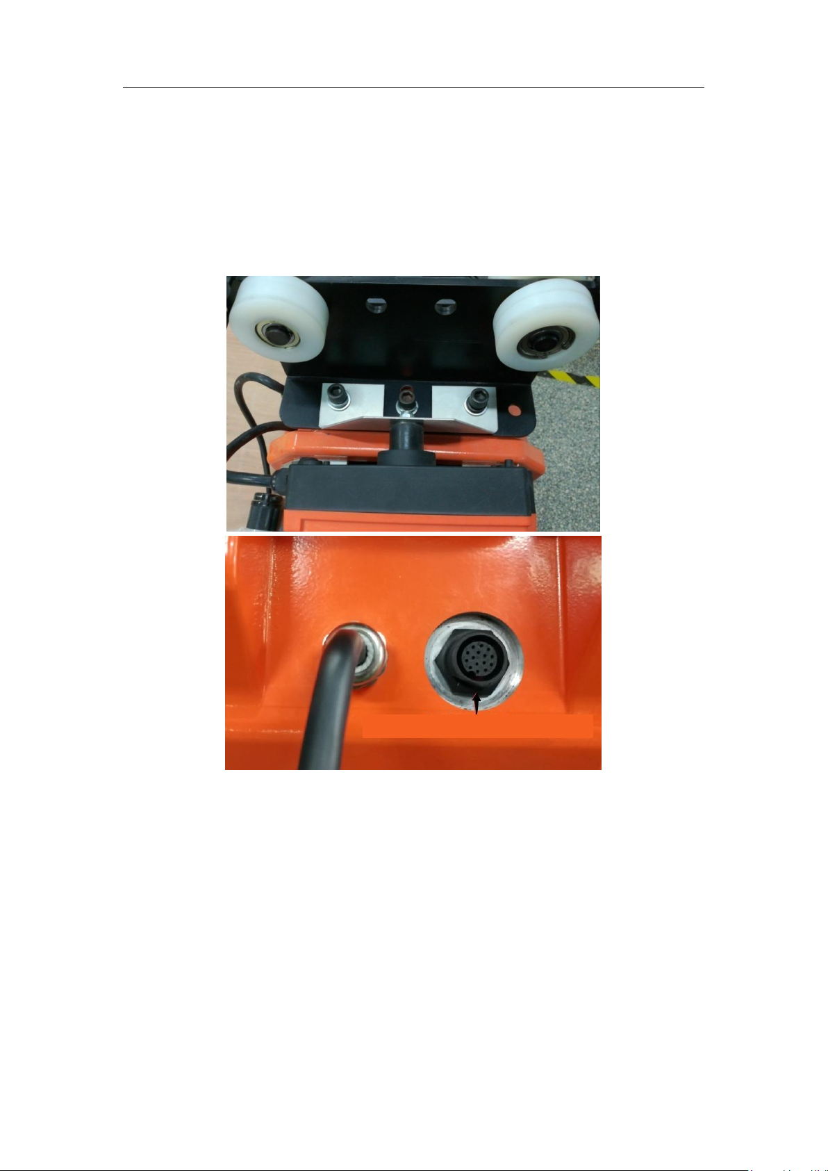
Intelligence Aided Lifting Equipment
Expansion interface of wireless module
Chapter VIII Annex
8.1 Use of wireless remote controller and receiver
1. Installation
2. Turn on the power. After the equipment is fully activated, click “Service” > “Wireless Switch”
to select “Open” and confirm by using the up and down selection buttons (UP, DOWN) in the
menu.
3. Restart the system (main power).
4. On the wireless handle
Up > Fast gear upwards
Down > Fast gear downwards
East > Slow gear upwards
West > Slow gear downwards
South > Suspension mode
North > Suspension unloading mode
On > Start the wireless module, as well as exist the suspension (suspension unloading) mode.
Stop > Function buttons will be invalid
74
Page 75
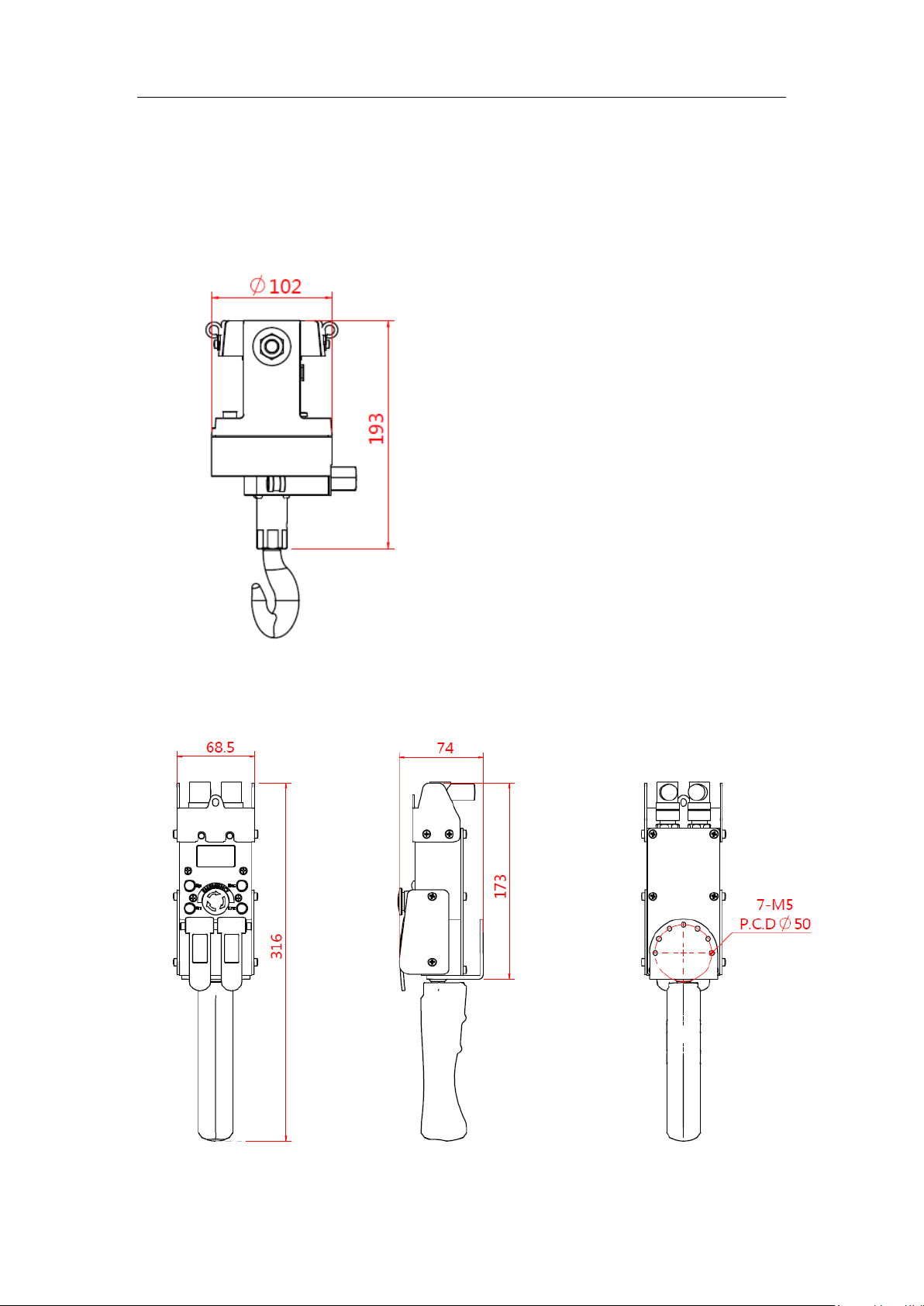
Intelligence Aided Lifting Equipment
Set the high/medium/slow gear in “Lifting Speed Setting” > “Inching Speed Setting”.
Note: In the “Wireless Handle” mode, the sliding (indefinitely variable speeds and all – touch)
handles can still be used normally, and their priority is higher than the wireless handle.
8.2 Dimensional drawing of H360 sliding circle
8.3 Dimensional drawing of indefinitely variable speeds handle
75
Page 76
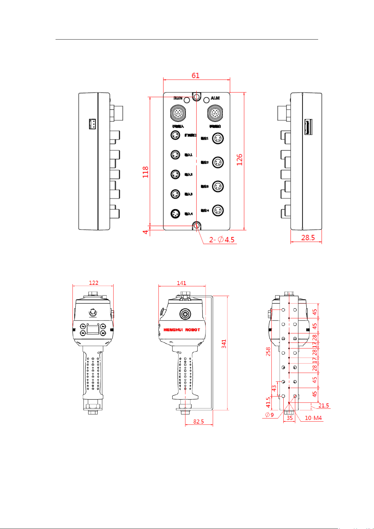
8.4 Extended box
Intelligence Aided Lifting Equipment
8.5 Remote installation sliding handle
76
Page 77

Intelligence Aided Lifting Equipment
77
Page 78

Intelligence Aided Lifting Equipment
Company name: Shaoxing Henghui Robot Technology Co., Ltd.
Company address: Industrial Functional Area, Zhangzhen Town, Shangyu District,
Shaoxing City, Zhejiang Province
Hangzhou office address: No. 6 Xianxing Road, Xianlin Subdistrict, Yuhang
District, Hangzhou City, Zhejiang Province
Website: http://www.hh-robot.com
78
 Loading...