

Page 1
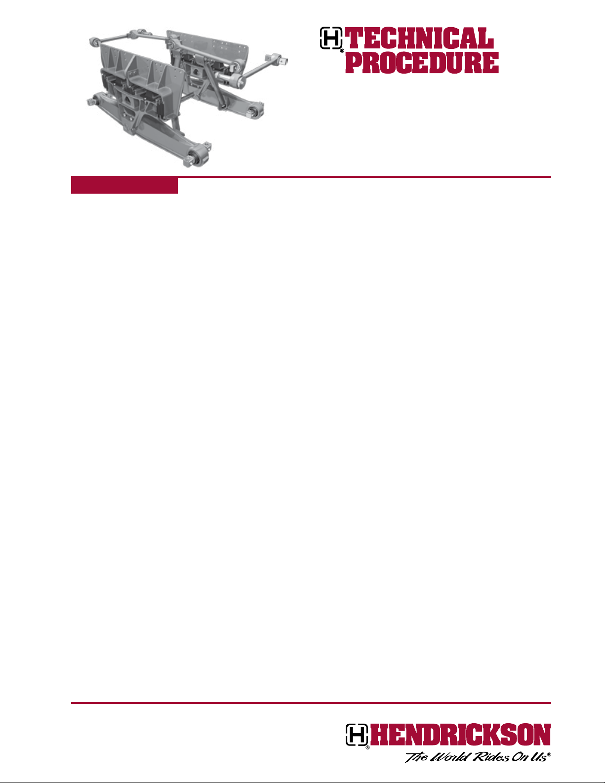
TABLE OF CONTENTS
ULTIMAAX® Rear Suspension
for Fire and Rescue Vehicles
SUBJECT: Service Instructions
LIT NO: 17730-299
DATE: July 2018 REVISION: B
Section 1 Introduction ........................2
Section 2 Product Description .................2
Section 3 Important Safety Notice ..............4
Section 4 Special Tools .......................8
Section 5 Parts List ..........................10
Section 6 Preventive Maintenance
Hendrickson Recommended
Inspection Intervals ................13
Component Inspection ................13
Center Bushings .....................14
Equalizing Beam End Connection ........15
Bar Pin End Bushings .................18
Bar Pin Shims .......................18
Beam End Axle Brackets ...............19
Frame Hanger Assembly ...............20
Shear springs .......................20
Progressive Load Springs (PLS) ..........21
Saddle Connection ...................22
Cross Tube. . . . . . . . . . . . . . . . . . . . . . . . . . 23
Section 7 Alignment & Adjustments
Drive Axle Pinion Angle ................27
Drive Axle Alignment ..................27
Axle Lateral Alignment .................29
Bar Pin Alignment ....................29
Section 8 Component Replacement
Fasteners ..........................32
Shock Absorber ......................32
Shear Spring / Frame Hanger Assembly /
Saddle Assembly ..................33
Progressive Load Spring (PLS) ...........38
Equalizing Beam .....................38
Equalizing Beam Center Bushing .........41
Bar Pin Style End Bushings .............44
Adapter Style End Bushings .............46
Cross Tube. . . . . . . . . . . . . . . . . . . . . . . . . . 50
Torque Rods ........................51
Torque Rod Bushings ..................52
Section 9 Troubleshooting Guide ..............57
Torque Rods ........................24
Shock Absorbers .....................25
Section 10 Torque Specications ...............58
Page 2
ULTIMAAX® for Fire and Rescue Vehicles
SECTION 1
Introduction
This publication is intended to acquaint and assist maintenance personnel in the preventive
maintenance, service, and repair of the ULTIMAAX
Fire and Rescue Vehicles.
NOTE Use only
It is important to read and understand the entire Technical Procedure publication prior to
performing any maintenance, service, or repair of this product. The information in this publication contains parts lists, safety information, product specifications, features, proper maintenance,
service, and repair instructions for ULTIMAAX suspensions.
Hendrickson reserves the right to make changes and improvements to its products and
publications at any time. Contact Hendrickson Tech Services for information on the latest version
of this manual at 1-866-755-5968 (toll-free U.S. and Canada), 1-630-910-2800 (outside U.S. and
Canada) or e-mail: [email protected].
The latest revision of this publication is available online at www.hendrickson-intl.com.
Hendrickson Genuine parts for servicing this suspension system.
SECTION 2
Product Description
ULTIMAAX is an advanced severe-duty rear rubber suspension designed specifically for fire and
rescue applications to balance outstanding durability, empty ride quality, loaded stability and
mobility. Through its unique design, the system offers premium ride quality in both empty and
loaded conditions, with increasing stability as the load increases.
®
Rear Rubber Suspension System for applicable
■
Equalizing beam — Formed and robotically welded to provide a narrow profile for weight
savings. Distributes load equally between axles to improve maneuverability, stability and
handling. Increases ground clearance with flat bottom design. Lowers the center of gravity to
increase stability.
■
Saddle — Triangular geometry provides structure and durability. Weight efficient design
helps to increase payload, while offering a considerable weight savings versus competitive
suspensions.
■
Frame hangers — Optimized design to balance durability and weight savings. Fabricated to
offer flexibility with multiple truck configurations.
■
Rubber shear springs — Primary springs in unloaded condition, providing superb ride quality.
React to longitudinal loads during braking and accelerating for minimal displacement.
■
Progressive load springs — Designed to balance empty ride quality and loaded stability.
Stiffness of progressive load spring increases as load increases, providing a unique balance
of empty ride quality and loaded stability.
■
Longitudinal torque rods — Engineered to optimize resistance to axle wind-up during acceleration and braking.
■
Transverse torque rods — Heavy-duty transverse torque rods ensure maximum lateral axle
control and straight line suspension stability.
2 17730-299
Page 3
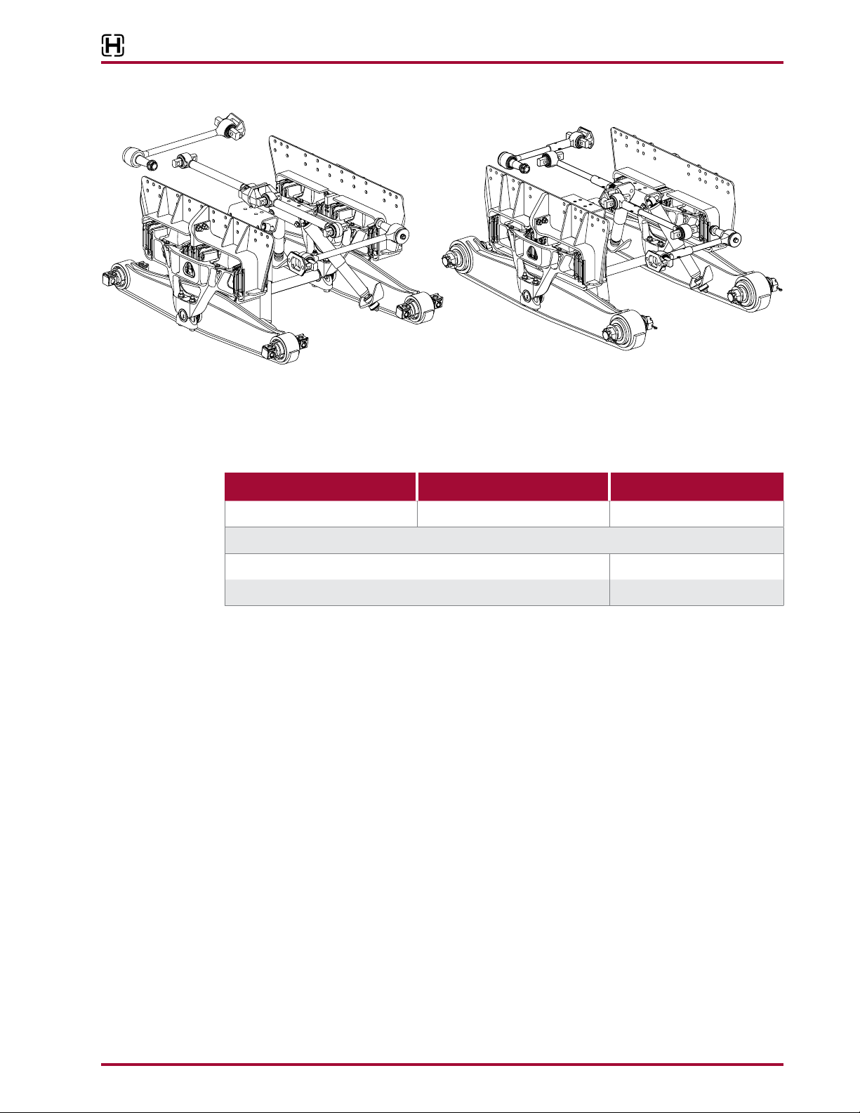
FIGURE 2-1
ULTIMAAX® for Fire and Rescue Vehicles
54K•58K Capacity
9½"•10"•10¼"•11½" Ride Height
63K Capacity
10"•10½" Ride Height
ULTIMAAX® SPECIFICATIONS
54K 58K 63K
Suspension Rating 54,000 lbs (24,494 kg) 58,000 lbs (26,308 kg) 63,000 lbs (28,576 kg)
Diagonal Articulation
Ride Heights 9½"•10"•10¼"•11½" (241 mm, 254 mm, 260 mm, 292 mm) 10", 10½" (254 mm, 267 mm)
Axle Spacing
Hendrickson approves the use of ULTIMAAX in fire / rescue applications. All such applications must comply with applicable Hendrickson
specifications and must also be approved by the respective vehicle manufacturer with the vehicle in its original, as-built configuration.
Contact Hendrickson and the respective vehicle manufacturer for approval of additional applications.
1. Suspension articulation may exceed vehicle’s capability and may be limited by vehicle manufacturer; vehicle manufacturer installed axle
stops may restrict suspension’s articulation.
2. Contact Hendrickson for availability of additional beam lengths.
For additional details regarding specifications, applications, capacities, operating service and maintenance instructions, refer to applicable
Hendrickson technical literature (available at www.hendrickson-intl.com) or contact Hendrickson at 1-866-768-5968.
Actual product performance may vary depending upon vehicle configuration, operation, service and other factors.
U.S. and foreign patents granted and / or pending.
1
2
54" (1,372 mm) 54", 56" (1,372 mm, 1,422, mm)
17½" (445 mm)
17730-299 3
Page 4
ULTIMAAX® for Fire and Rescue Vehicles
SECTION 3
Important Safety Notice
Proper maintenance, service and repair are important to the reliable operation of the suspension.
The procedures recommended by Hendrickson and described in this technical publication are
methods of performing such maintenance, service and repair.
This technical publication should be read carefully to help prevent personal injury and to assure
that proper methods are used. Improper maintenance, service or repair may damage the vehicle,
cause personal injury, render the vehicle unsafe in operation, or void the manufacturer's warranty.
Failure to follow the safety precautions in this manual can result in personal injury and/or property
damage. Carefully read and understand all safety related information within this publication, on
all decals and in all such materials provided by the vehicle manufacturer before conducting any
maintenance, service or repair.
■
EXPLANATION OF SIGNAL WORDS
Hazard “Signal Words” (Danger • Warning • Caution) appear in various locations throughout this
publication. Information accented by one of these signal words must be observed to help minimize the risk of personal injury to service personnel, or possibility of improper service methods
which may damage the vehicle or render it unsafe.
This is the safety alert symbol. It is used to alert you to potential personal injury haz-
ards. Obey all safety messages that follow this symbol to avoid possible injury or death.
Additional Notes or Service Hints are utilized to emphasize areas of procedural importance and provide suggestions for ease of repair. The following definitions indicate the use of
these signal words as they appear throughout the publication.
INDICATES AN IMMINENTLY HAZARDOUS SITUATION, WHICH IF NOT AVOIDED, WILL RESULT IN SERIOUS
INJURY OR DEATH.
INDICATES A POTENTIAL HAZARDOUS SITUATION WHICH, IF NOT AVOIDED, CAN RESULT IN SERIOUS
INJURY OR DEATH.
INDICATES A POTENTIAL HAZARDOUS SITUATION WHICH, IF NOT AVOIDED, MAY RESULT IN MINOR OR
MODERATE INJURY.
NOTE An operating procedure, practice condition, etc. which, is essential to emphasize.
SERVICE HINT A helpful suggestion that will make the servicing being performed a little easier and/or faster.
Also note that particular service operations may require the use of special tools designed for specific
purposes. These special tools can be found in the “Special Tools” Section of this publication.
The torque symbol alerts you to tighten the fasteners to a specific torque value. See Torque
Specifications Section of this publication.
4 17730-299
Page 5
■
SAFETY PRECAUTIONS
FASTENERS
DISCARD USED FASTENERS. ALWAYS USE NEW FASTENERS TO COMPLETE A REPAIR. FAILURE TO DO
SO COULD RESULT IN FAILURE OF THE PART, OR MATING COMPONENTS, ADVERSE VEHICLE HANDLING,
PERSONAL INJURY, OR PROPERTY DAMAGE.
LOOSE OR OVER TORQUED FASTENERS CAN CAUSE COMPONENT DAMAGE, ADVERSE VEHICLE
HANDLING, PROPERTY DAMAGE, OR SEVERE PERSONAL INJURY. MAINTAIN CORRECT TORQUE VALUE
AT ALL TIMES. CHECK TORQUE VALUES ON A REGULAR BASIS AS SPECIFIED, USING A REGULARLY
CALIBRATED TORQUE WRENCH. TORQUE VALUES SPECIFIED IN THIS TECHNICAL PUBLICATION ARE FOR
HENDRICKSON SUPPLIED FASTENERS ONLY. IF NON-HENDRICKSON FASTENERS ARE USED, FOLLOW
TORQUE SPECIFICATION LISTED IN THE VEHICLE MANUFACTURER’S SERVICE MANUAL.
TORCH/WELDING
DO NOT USE A CUTTING TORCH TO REMOVE ANY FASTENERS OR BUSHINGS. THE USE OF HEAT
ON SUSPENSION COMPONENTS WILL ADVERSELY AFFECT THE STRENGTH OF THESE PARTS. A
COMPONENT DAMAGED IN THIS MANNER CAN RESULT IN THE ADVERSE VEHICLE HANDLING AND
POSSIBLE PERSONAL INJURY OR PROPERTY DAMAGE.
EXERCISE EXTREME CARE WHEN HANDLING OR PERFORMING MAINTENANCE IN THE AREA OF THE
EQUALIZING BEAM. DO NOT CONNECT ARC WELDING GROUND LINE TO THE EQUALIZING BEAM. DO
NOT STRIKE AN ARC WITH THE ELECTRODE ON THE EQUALIZING BEAM AND AXLE. DO NOT USE HEAT
NEAR THE EQUALIZING BEAM ASSEMBLY. DO NOT NICK OR GOUGE THE EQUALIZING BEAM. SUCH
IMPROPER ACTIONS CAN DAMAGE THE EQUALIZING BEAM ASSEMBLY AND CAUSE ADVERSE VEHICLE
HANDLING AND POSSIBLE PERSONAL INJURY OR PROPERTY DAMAGE.
ULTIMAAX® for Fire and Rescue Vehicles
LOAD CAPACITY
ADHERE TO THE PUBLISHED CAPACITY RATINGS FOR THE SUSPENSION. ADD-ON AXLE ATTACHMENTS
AND OTHER LOAD TRANSFERRING DEVICES CAN INCREASE THE SUSPENSION LOAD ABOVE ITS RATED
AND APPROVED CAPACITIES, WHICH CAN RESULT IN COMPONENT DAMAGE AND ADVERSE VEHICLE
HANDLING, POSSIBLY CAUSING PERSONAL INJURY OR PROPERTY DAMAGE.
MODIFYING COMPONENTS
DO NOT MODIFY OR REWORK PARTS WITHOUT AUTHORIZATION FROM HENDRICKSON. DO NOT
USE SUBSTITUTE OR REPLACEMENT COMPONENTS NOT AUTHORIZED BY HENDRICKSON. USE OF
MODIFIED, REWORKED, SUBSTITUTE OR REPLACEMENT PARTS NOT AUTHORIZED BY HENDRICKSON
MAY NOT MEET HENDRICKSON’S SPECIFICATIONS, AND CAN RESULT IN FAILURE OF THE PART,
ADVERSE VEHICLE HANDLING, AND POSSIBLE PERSONAL INJURY OR PROPERTY DAMAGE AND WILL
VOID WARRANTY. USE ONLY HENDRICKSON AUTHORIZED REPLACEMENT PARTS.
PERSONAL PROTECTIVE EQUIPMENT
ALWAYS WEAR PROPER EYE PROTECTION AND OTHER REQUIRED PERSONAL PROTECTIVE EQUIPMENT
TO HELP PREVENT PERSONAL INJURY WHEN PERFORMING VEHICLE MAINTENANCE, REPAIR OR
SERVICE.
PROCEDURES AND TOOLS
A TECHNICIAN USING A SERVICE PROCEDURE OR TOOL WHICH HAS NOT BEEN RECOMMENDED BY
HENDRICKSON MUST FIRST SATISFY HIMSELF THAT NEITHER HIS SAFETY NOR THE VEHICLE'S SAFETY
WILL BE JEOPARDIZED BY THE METHOD OR TOOL SELECTED. INDIVIDUALS DEVIATING IN ANY MANNER
FROM THE INSTRUCTIONS PROVIDED WILL ASSUME ALL RISKS OF CONSEQUENTIAL PERSONAL INJURY
OR DAMAGE TO EQUIPMENT INVOLVED.
17730-299 5
Page 6
ULTIMAAX® for Fire and Rescue Vehicles
SUPPORT THE VEHICLE PRIOR TO SERVICING
PLACE THE VEHICLE ON A LEVEL FLOOR AND CHOCK THE WHEELS TO PREVENT THE VEHICLE FROM
MOVING OR ROLLING. DO NOT WORK AROUND OR UNDER A RAISED VEHICLE SUPPORTED BY ONLY
A FLOOR JACK OR OTHER LIFTING DEVICE. ALWAYS SUPPORT A RAISED VEHICLE WITH RIGID SAFETY
STANDS. FAILURE TO DO SO CAN CAUSE SERIOUS PERSONAL INJURY OR DAMAGE TO EQUIPMENT.
IMPROPER JACKING METHOD
IMPROPER JACKING METHODS CAN CAUSE STRUCTURAL DAMAGE WHICH CAN CAUSE ADVERSE
VEHICLE HANDLING, PROPERTY DAMAGE OR SEVERE PERSONAL INJURY AND WILL VOID
HENDRICKSON’S WARRANTY.
■
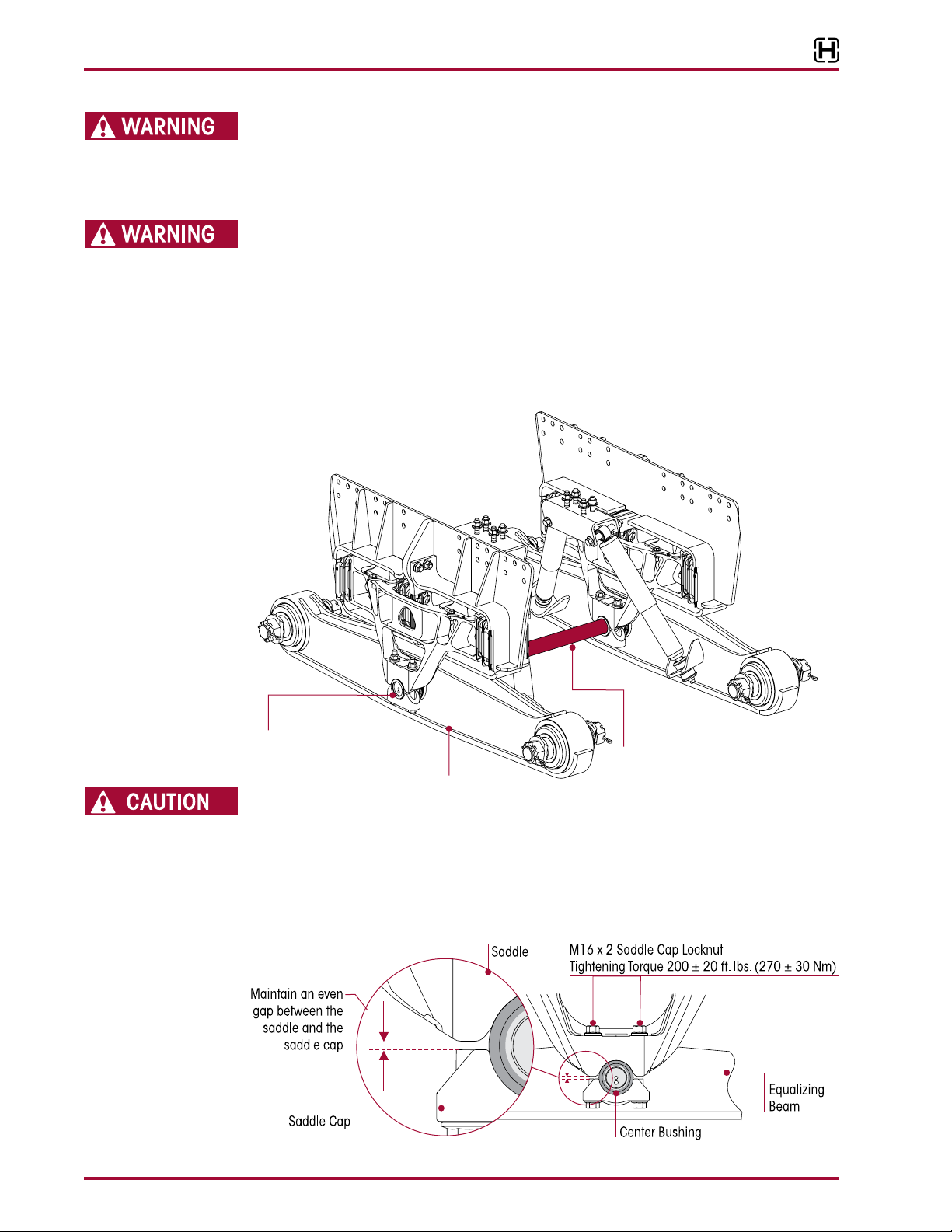
DO NOT USE THE SUSPENSION CROSS TUBE AS A JACKING POINT, SEE FIGURE 3-1, REFER TO
VEHICLE MANUFACTURER FOR PROPER JACKING INSTRUCTIONS.
■
ACCEPTABLE LIFTING POINTS FOR A VEHICLE AT THE RATED LOAD INCLUDE BUT ARE NOT
LIMITED TO: THE AXLE, EQUALIZING BEAM, AND THE VEHICLE FRAME RAIL. REFER TO THE VEHICLE
MANUFACTURER FOR PROPER JACKING INSTRUCTIONS.
FIGURE 3-1
63K ShownULTIMAAX
Center Bushing
greaseDO NOT
Equalizing
SADDLE CONNECTION
A SADDLE ASSEMBLY IS ATTACHED TO THE CENTER BUSHING OF EACH EQUALIZING BEAM WITH TWO
(2) SADDLE CAPS. EACH SADDLE CAP USES TWO (2) BOLTS TO CLAMP THE CENTER BUSHING INNER
METAL TO THE SADDLE. EACH SADDLE CAP MUST BE INSTALLED SO THAT THERE IS AN EVEN GAP
BETWEEN THE SADDLE CAP AND THE BASE OF THE SADDLE LEGS AS SHOWN IN FIGURE 3-2. IF EACH
SADDLE CAP IS NOT INSTALLED EVENLY, THE SADDLE LEGS COULD BECOME DEFORMED, RESULTING
IN BENT BOLTS OR DAMAGED SADDLES.
FIGURE 3-2
Beam
Cross Tube
grease or
DO NOT
use as a jacking point
6 17730-299
Page 7
TORQUE ROD ASSEMBLY
THE ULTIMAAX SUSPENSION INCORPORATES LONGITUDINAL AND TRANSVERSE TORQUE RODS FOR
VEHICLE STABILITY. IF THESE COMPONENTS ARE DISCONNECTED OR ARE NON-FUNCTIONAL THE
VEHICLE SHOULD NOT BE OPERATED. FAILURE TO DO SO CAN RESULT IN ADVERSE VEHICLE HANDLING
AND POSSIBLE TIRE CONTACT WITH THE FRAME OR THE SUSPENSION.
PARTS CLEANING
SOLVENT CLEANERS CAN BE FLAMMABLE, POISONOUS, AND CAUSE BURNS. TO HELP AVOID SERIOUS
PERSONAL INJURY, CAREFULLY FOLLOW THE MANUFACTURER’S PRODUCT INSTRUCTIONS AND
GUIDELINES AND THE FOLLOWING PROCEDURES:
1. WEAR PROPER EYE PROTECTION.
2. WEAR CLOTHING THAT PROTECTS YOUR SKIN.
3. WORK IN A WELL-VENTILATED AREA.
4. DO NOT USE GASOLINE OR SOLVENTS THAT CONTAIN GASOLINE. GASOLINE CAN EXPLODE.
5. HOT SOLUTION TANKS OR ALKALINE SOLUTIONS MUST BE USED CORRECTLY. FOLLOW THE
MANUFACTURER’S RECOMMENDED INSTRUCTIONS AND GUIDELINES CAREFULLY TO HELP
PREVENT PERSONAL ACCIDENT OR INJURY.
DO NOT USE HOT SOLUTION TANKS OR WATER AND ALKALINE SOLUTIONS TO CLEAN GROUND OR
POLISHED PARTS. DOING SO WILL CAUSE DAMAGE TO THE PARTS AND VOID WARRANTY.
ULTIMAAX® for Fire and Rescue Vehicles
17730-299 7
Page 8
ULTIMAAX® for Fire and Rescue Vehicles
SECTION 4
Special Tools
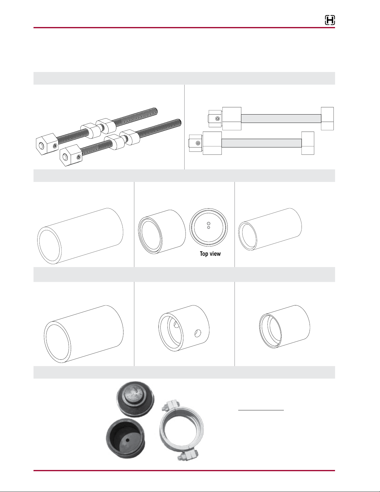
SADDLE TOOLS
DISASSEMBLY TOOL
Hendrickson Part No. 66086-113L
CENTER BUSHING TOOLS
RECEIVING TOOL
Hendrickson Part No. 66086-112
ASSEMBLY TOOL
Hendrickson Part No. 66086-108L
INSTALLATION TOOL
Hendrickson Part No. 66086-107
REMOVAL TOOL
Hendrickson Part No. 66086-110
BAR PIN STYLE END BUSHING TOOLS – 54K • 58K
RECEIVING TOOL
Hendrickson Part No. 66086-111
INSTALLATION TOOL
Hendrickson Part No. 66086-106
ADAPTER STYLE END BUSHING TOOLS – 63K
End Bushing
Removal / Replacement Adapter
OTC Part Number 208350
Center Bushing
Removal / Replacement Adapter
OTC Part Number 28541
Not Needed for this publication
Clamp
OTC Part Number 208349
REMOVAL TOOL
Hendrickson Part No. 66086-109
Hendrickson Part No. 66086-101
OTC Part No. 1763
Visit otctools.com
8 17730-299
Page 9

ULTIMAAX® for Fire and Rescue Vehicles
TORQUE ROD BUSHING TOOLS
These shop made tools are made from cold rolled steel or equivalent. The drawings are
for reference only, Hendrickson does not supply these tools.
RECEIVING TOOL INSTALLATION / REMOVAL TOOL ULTRA ROD PLUS FUNNEL TOOL
Hendrickson Part No. 66086-000L
17730-299 9
Page 10
ULTIMAAX® for Fire and Rescue Vehicles
SECTION 5
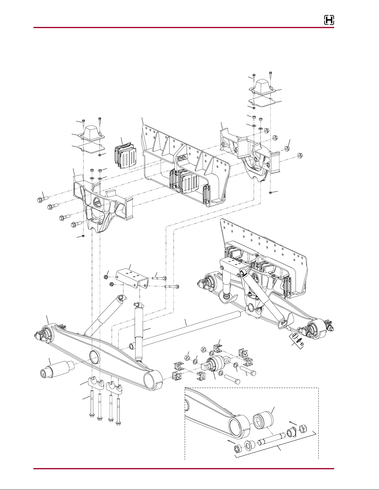
Parts List
■
54K – Rosenbauer 9½" Ride Height • KME 10" Ride Height
■
58K – Seagrave 9½", 10¼" and 11½" Ride Height
■
63K – Rosenbauer 10½" Ride Height, KME 10" Ride Height
11
15
13
14
(if equipped)
17
18
16
12
16
23
22
17
23
22
15
16
13
14 (if equipped)
19
16
25
27
1
2
20
21
24
26
10
4
7
6
6
3
5
63K Beam End Conguration
24
8
9
10 17730-299
Page 11
ULTIMAAX® for Fire and Rescue Vehicles
VEHICLE
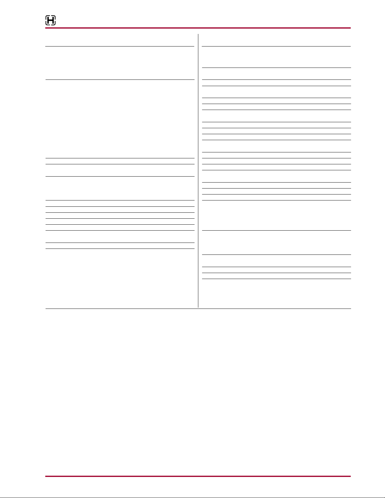
KEY NO. PART NO. DESCRIPTION QTY.
1 Equalizing Beam Assembly with Shock Bracket 2
78489-540 54K - Rosenbauer, KME; 58K - Seagrave,
Includes Key Nos. 2-3
78634-540 63K - KME, Includes Key Nos. 2, 8
78634-560 63K - Rosenbauer, Includes Key Nos. 2, 8
Equalizing Beam Bushing Service Kits
• 54K / 58K Bar Pin Style
60961-755 Center and End Bushing, One Beam, Includes
Key No. 2-3,5-7, 21-23
60961-752 End Bushing, One Wheel End, Includes
Key Nos. 3-7
End Bushing Fasteners, Includes Key Nos. 5-7
56659-001 Tandem
56659-005 One Beam
34013-104 One Wheel End
• 63K Through Bolt Style
34013-052 End Bushing and Adapter Service Kit,
One Wheel End, Includes Key Nos. 8-9
2 Center Bushing 2
3 *Bar Pin End Bushing Assembly, 54K/58K,
Includes Key No. 4a
4 Bar Pin Shim 8
a 50130-000 0.19" / 0.19" Standard
b 50131-000 0.25" / 0.12" Optional
c 57026-000 0.375" Optional at shim
5 *1"-8 UNC x 6" Bolt 8
6 *1" Hardened Washer 16
7 *1"-8 UNC Locknut 8
8 *End Bushing, 63K 4
9 21140-007 End Bushing Adapter Assembly, 63K 4
60961-759 Cross Tube Service Kit, Includes Key No. 10
and Weldable Loose Plug (Not Shown)
10 44642-008 Cross Tube - 1140 mm 1
11 Frame Hanger 2
• 34" Width - 54K/63K KME
78726-001 10" Ride Height
• 341⁄8" Width - 58K Seagrave
78592-002 9½" and 10¼" Ride Height
78592-005 11½" Ride Height
• 35" Width - Rosenbauer
70912-005 10½" Ride Height, 63K
70912-206 9½" Ride Height, 54K
VEHICLE
KEY NO. PART NO. DESCRIPTION QTY.
60961-749 Shear and Progressive Load Spring Service Kit,
One Side, Includes Key Nos. 12-13,15-16,
18-19, 21-23, 28
60961-750 Shear Spring Service Kit, One Side
Includes Key Nos. 12, 18-19, 21-23, 28
12 *Shear Spring 8
60961-751 Progressive Load Spring Service Kit, One Side
Includes Key Nos. 13, 15-16
13 *Progressive Load Spring 4
14 70824-001 Spacer, 63K only 4
34013-196 Progressive Load Spring Fasteners Service Kit,
One Side, Includes Key Nos. 15-16
15 *M10 x 1.5 x 40 mm 6G Flange Bolt 8
16 *M10 x 1.5 Flange Lock Nut 8
17 70886-000 Saddle 4
34013-197 Saddle Only Fastener Kit, One Side,
Includes Key Nos. 18-19
18 *M20 x 1.5 x 75 mm Flange Bolt 8
19 *M20 x 1.5 Flange Nut 8
20 77205-001 Saddle Cap 4
60961-768 Saddle Cap Fastener Service Kit, One Side,
Includes Key Nos. 21-23
21 *M16 x 2 x 6G x 180 mm Flange Bolt 8
22 *M16 Flat Washer 8
23 *M16 x 2 x 6H Nut 8
24 Shock Absorber 4
60680-015L 9½" Ride Height - 54K Rosenbauer, 58K Seagrave
60680-016L 10¼", 11½" Ride Height - 58K Seagrave
10" Ride Height - 54K and 63K KME
10½" Ride Height - 63K Rosenbauer
25 Upper Shock Bracket 2
77591-002 54K/63K Rosenbauer
77591-006 54K/63K KME
77591-007 58K Seagrave
60961-818 Upper Shock Fasteners Service Kit, One Beam,
Includes Key Nos. 26-27
26 *M16 x 2 x 140 mm Flange Bolt 4
27 *M16 x 2 Flange Nut 4
28 70867-001 P-80 Lubricant - 10 ml (Not Shown) As Req.
NOTES: * Item included in service kit/assembly only, part not sold separately.
** Transverse torque rods are mandatory for the ULTIMAAX rear suspension regardless of axle spacing.
Hendrickson Lit. No. 48422-592 – ULTIMAAX Gauge Card can be used to measure in unloaded condition (1) the length of cut / split, (2)
depth of separation and (3) the height of the progressive load spring (PLS).
17730-299 11
Page 12
ULTIMAAX® for Fire and Rescue Vehicles
7
■
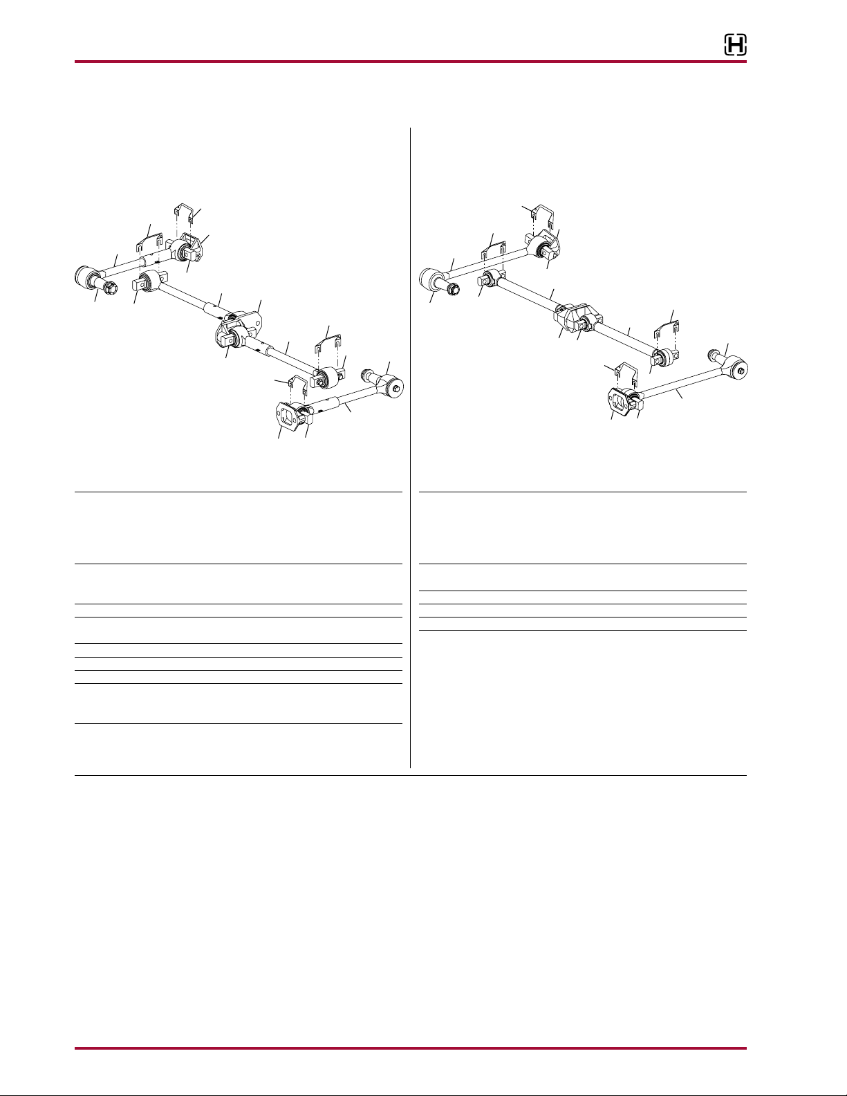
Torque Rod Conguration
54K / 63K – Rosenbauer
9.5" and 10½" Ride Height
54K / 63K – KME 10" Ride Height
9b
4
6
3
VEHICLE
KEY NO. PART NO. DESCRIPTION QTY.
1 Two-piece Longitudinal Torque Rod 2
65781-005 Rosenbauer, Includes Key Nos. 2a, 3 2
65781-006 KME, Includes Key Nos. 2b, 3 2
2 XTRB Straddle Bushing to Cross Member Bracket 2
a 66649-005L Rosenbauer
b 66649-002L KME
3 66649-003L XTRB Straddle Bushing to Axle Bracket, 2
4 65781-002 *Two-piece Transverse Torque Rod, 2
5 66649-002L XTRB Straddle Bushing 6
6 66649-004 XTRB Taper Bushing 2
7 22186-000 Torque Rod Frame Bracket 2
8 Torque Rod Cross Member Bracket 2
a 30828-000 Rosenbauer
b 22186-000 KME
9 Torque Rod Shim As Req.
a 49689-000 111 mm
b 67779-002 133 mm
9a
7
5
1
8
9b
1
2
9a
5
Straddle/Straddle
Straddle/Tapper, Includes Key Nos. 5-6
3
6
4
58K – Seagrave
9½", 10¼" and 11½" Ride Height
6
6
2
4
3
VEHICLE
KEY NO. PART NO. DESCRIPTION QTY.
1 ULTRA ROD® PLUS™ Longitudinal Torque Rod,
72100-495 Front, Seagrave 1
72100-635 Rear, Seagrave 1
2 72950-610 *ULTRA ROD PLUS Transverse Torque Rod, 2
3 64400-003 ULTRA ROD PLUS Straddle Bushing 6
4 64400-004 ULTRA ROD PLUS Taper Bushing 2
5 46015-000 Torque Rod Frame Bracket 4
6 67779-002 Torque Rod Shim - 133 mm As Req.
5
3
1
6
1
5
3
6
3
2
3
5
Straddle/Straddle, Includes Key No. 3
Straddle/Taper, Includes Key Nos. 3-4
4
NOTES: * Transverse torque rods are mandatory for the ULTIMAAX rear suspension regardless of axle spacing.
12 17730-299
Page 13
ULTIMAAX® for Fire and Rescue Vehicles
SECTION 6
Preventive Maintenance
Following appropriate inspection procedures is important to help ensure the proper maintenance
and operation of the suspension system and component parts. Hendrickson recommends the
ULTIMAAX rear suspension be inspected at pre-delivery, the first in-service inspection and regular preventive maintenance intervals. Off-highway and severe service operating conditions may
require more frequent inspections than on-highway or less severe service operations. Inspection
must include the following items and other components referenced in this section.
NOTE Torque values shown in this publication apply only if Hendrickson supplied fasteners are used. If
non-Hendrickson fasteners are used, follow the torque specification listed in the vehicle manufacturer’s service manual.
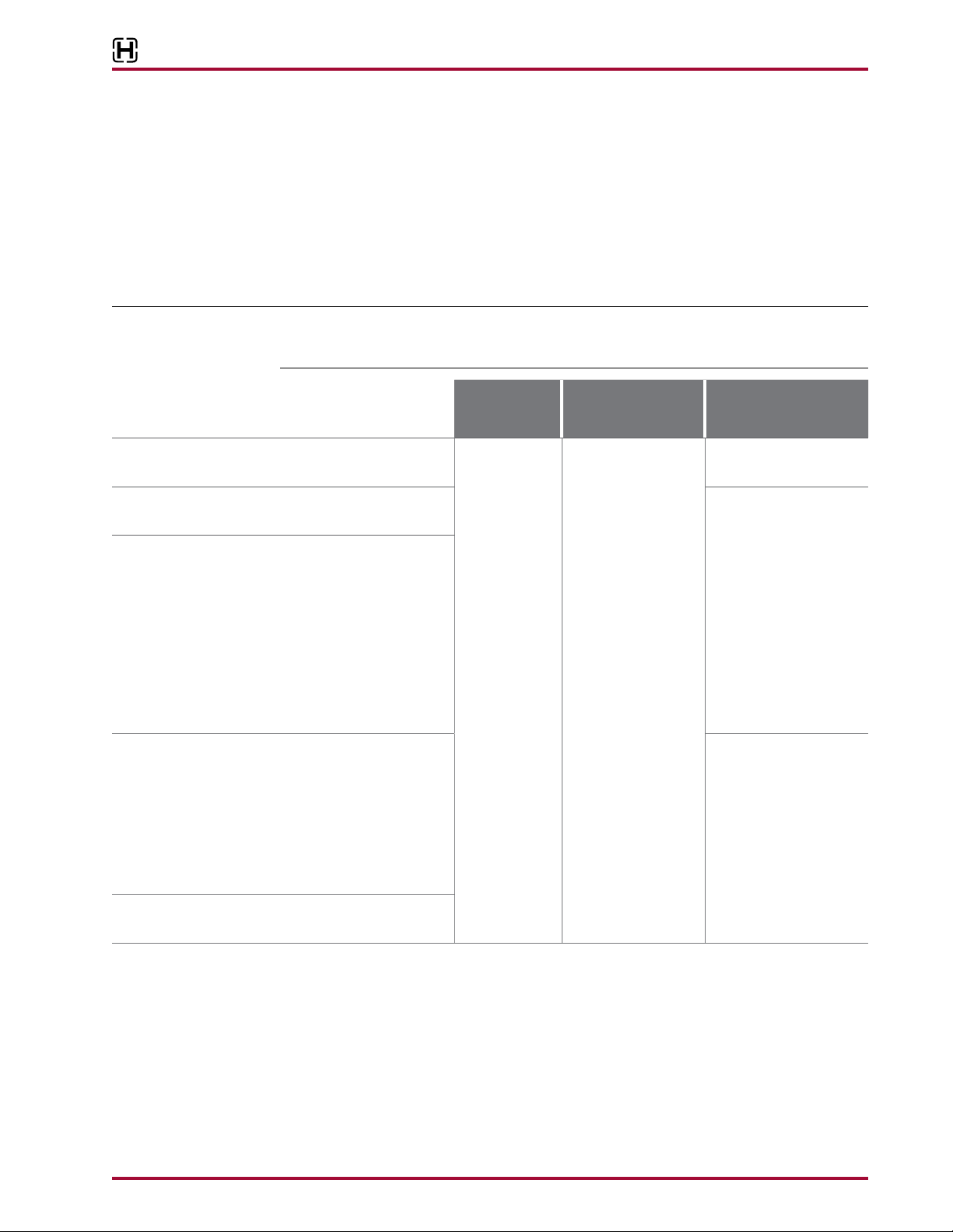
HENDRICKSON RECOMMENDED
INSPECTION INTERVALS
Inspect Progressive Load Spring
Inspect torque rods and equalizing beam end
connections
Visually Inspect proper assembly and function. Check
for all of the following and replace components as
necessary:
• Signs of unusual movement, loose or missing
components
• Signs of abrasive or adverse contact with other
components (example: brake lines, wheel wells,
frame hangers, etc.)
• Damaged, or cracked parts
• Proper suspension function, alignment
Inspect fasteners for proper torque as recommended
in the Torque Specification Section of this publication
with special attention to the following suspension
connections:
• Equalizing beam end connection
• Saddle cap connection
• Frame hanger to frame rail connection
• Center Bushing
PRE-DELIVERY
INSPECTION
Within the first
500 Miles
(500 km)
FIRST IN-SERVICE
INSPECTION
Within the first
1,500 Miles
(2,000 km) or
100 Hours
PREVENTIVE
MAINTENANCE
Every 3 Months /
600 Hours
Every 6 Months /
1200 Hours
or
25,000 Miles /
40,000 km
Every 12 Months /
2400 Hours
Verify the alignment of axles are within the vehicle
manufacturer’s tolerances.
COMPONENT INSPECTION
Following appropriate inspection procedures is important to help ensure the proper maintenance
and operation of the ULTIMAAX heavy-duty rear suspension system and component parts. Look for
and replace worn, damaged, bent or cracked parts.
■
Cross tube — Clean the cross tube and inspect it for cracks or excessive wear 8" to 10" from
each end where it enters into the equalizing beam center bushings. Use a straight edge to
check the straightness of the cross tube. If there is a doubt as to fracture, wear or straightness,
replacement is necessary.
17730-299 13 Preventive Maintenance
Page 14
ULTIMAAX® for Fire and Rescue Vehicles
and the second locating
Bottom Hole
■
Equalizing beam assembly — Check the overall condition of the equalizing beam for dents,
dings, or other damage. Check the beam end connections for tearing or extreme bulging.
Check for any metal-to-metal contact in the bushed joints. Refer to Equalizing Beam End
Connection Inspection in this section.
■
Fasteners — Look for any loose, missing or damaged fasteners on the entire suspension.
Ensure all fasteners are tightened to a torque value within the specified torque range. See recommended torque specifications for Hendrickson supplied fasteners in Torque Specification
Section of this publication. For fasteners not supplied by Hendrickson, see vehicle manufacturer. Use a calibrated torque wrench to check torque in the tightening direction. As soon as
the fastener starts to move, record the torque. Correct the torque as necessary.
NOTE Hendrickson recommends the use of Grade 8 bolts, hardened washers, and Grade C locknuts.
Hardened washers are not necessary when flange head fasteners are used.
NOTE Torque values shown in this publication apply only if Hendrickson supplied fasteners are used. If
non-Hendrickson fasteners are used, follow the torque specification listed in the vehicle manufacturer’s service manual.
■
Saddle cap fasteners — Inspect the locknuts for proper torque to prevent wear of the beam
center bushing into the saddle. See Torque Specification Section of this publication for recommended torque requirements.
■
Shock absorbers — Look for any signs of dents or leakage. Misting is not considered a leak.
See Shock Absorber Inspection in this section.
■
Transverse torque rods / Longitudinal torque rods — The torque rods must be connected
and in good working condition when operating the vehicle.
■
Wear and damage — Inspect all parts of the suspension for wear and damage. Look for bent
or cracked parts.
See vehicle manufacturer’s applicable publications for other preventive maintenance
requirements.
CENTER BUSHINGS
VISUAL INSPECTION
An inspection of the center bushing is necessary when a vehicle is in the shop for major repair
work and at regular preventive maintenance intervals.
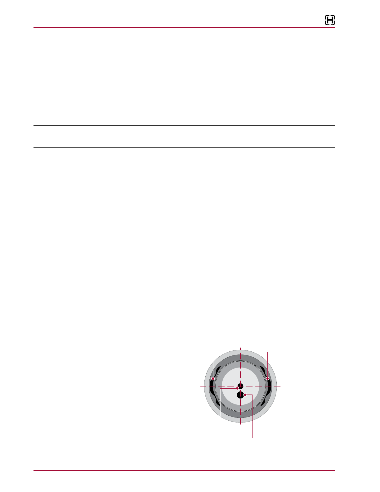
NOTE ULTIMAAX center bushing is designed with voids at front and rear, see Figure 6-1. These voids are
not an indication of wear.
FIGURE 6-1
1. Visually inspect the center bushing for signs of movement or
excessive wear such as frayed,
bulging or distorted rubber in the
center bushing.
2. Replacement is necessary if:
■
Any metal to metal contact is
visible.
■
Any signs that the bushing
inner metal is not centered in
the bushing.
■
Any equalizing beam to saddle contact.
Void
Center
Hole
C
L
Void
Horizontal Centerline
Verify the voids are
perpendicular to the
horizontal centerline
hole is on the bottom
Second Locating
Preventive Maintenance 14 17730-299
Page 15
ULTIMAAX® for Fire and Rescue Vehicles
A
end hub appearing
centerline of the end bushing in the axle bracket
the centerline of the end bushing in the axle bracket
EQUALIZING BEAM END CONNECTION
An inspection of the beam end connections are necessary when a vehicle is in the shop for
major repair work and at regular preventive maintenance intervals. Periodic visual inspection by
the driver and service personnel is also recommended.
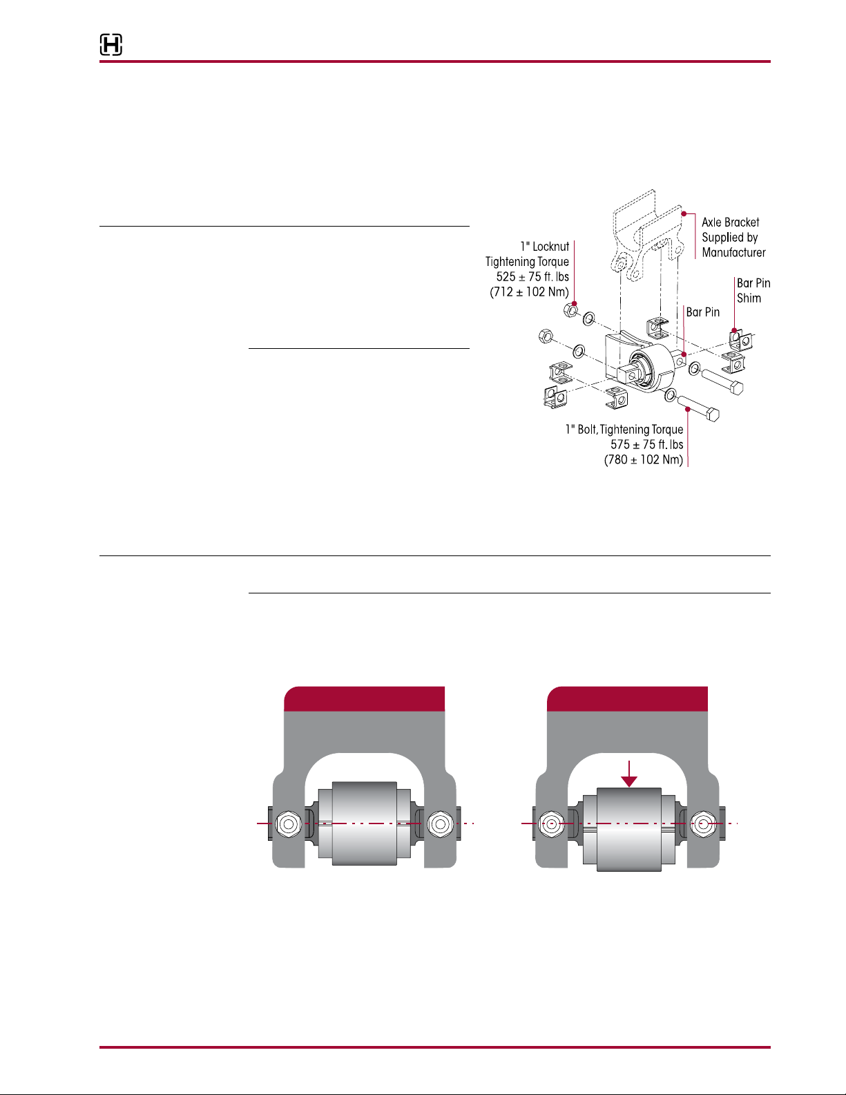
FIGURE 6-2
■
Bar Pin Style, see Figure 6-2
NOTE The equalizing beam end connection
requires that the fasteners are tightened
to torque specifications, see Figure 6-2,
to maintain the clamp load of the axle
bracket legs to the bar pin. All bushing
motion is accommodated by rubber
deflection.
VISUAL INSPECTION
1. Chock the wheels.
2. Visually inspect suspension components for signs of movement or
excessive wear.
■
Inspect alignment shims in
equalizing beam end for looseness. Lightly tap on the alignment shims to see if they
can be moved. If movement is detected, tighten fasteners to the proper torque value, see
Figure 6-2.
■
Inspect the equalizing beam end connection for signs of excessive wear or looseness.
SERVICE HINT An equalizing beam end connection that is visibly cleaner than the other connections may indi-
cate a loose connection.
■
Look for worn, frayed or distorted rubber in the bar pin beam end bushing, see Figure 6-3.
■
Look for the equalizing beam to be lower in the beam hanger, see Figure 6-3.
■
If the bar pin beam end bushing is visually offset a floor jack test should be performed,
refer to Jack Test in this section.
FIGURE 6-3
GOOD BUSHING
bushing will result in the equalizing beamGOOD
to be with thecentered
C
WORN BUSHING
Axle BracketAxle Bracket
L
A bushing will result in the equalizing beamWORN
end hub appearing to be /" (15 mm)
C
L
5
8
offset/below
17730-299 15 Preventive Maintenance
Page 16

ULTIMAAX® for Fire and Rescue Vehicles
Gap in rubber
of bar pin end
ed Nut
1/" Slotted Nut
63K ShownULTIMAAX
FIGURE 6-4
JACK TEST
1. Place a jack under each beam end as shown. Raise the
jack to check for movement in the connection or rubber
components, see Figure 6-4.
NOTE The gap at each side of the visible rubber on the lower
part of the end bushing is normal, see Figure 6-4, and is
not an indication to replace the bushing. Because all rubber
end bushings are in compression, with the load bearing on
the top side, the lower side of the rubber is slightly relieved,
allowing the rubber to move inward, and a gap appears.
PHYSICAL INSPECTION
IF BAR PIN MOVEMENT OR LOOSENESS IS NOTED IN ANY OF
THE EQUALIZING BEAM END HUBS, DO NOT OPERATE THE VEHICLE. REPLACE THE RUBBER END
BUSHINGS AND ALL CONNECTING PARTS IF NECESSARY. THE ABOVE CONDITION CAN RESULT
IN COSTLY REPAIR, DOWNTIME, POSSIBLE SEPARATION OF COMPONENTS, ADVERSE VEHICLE
HANDLING, PROPERTY DAMAGE, OR PERSONAL INJURY.
Floor
Jack
Axle Bracket
bushing is
normal
SERVICE HINT An equalizing beam end connection that is visibly cleaner than the other connections may indi-
cate a loose connection.
2. If bar pin end bushing movement or looseness is detected in the equalizing beam end hub,
replace the end bushings and all connecting parts. Refer to the Component Replacement
Section of this publication.
3. Check and record torque values, as received, for each 1" bar pin fastener, see Figure 6-2.
Ensure all fasteners are tightened to:
■
At the locknut to 525 ± 75 foot pounds torque, or
■
At the bolt head to 575 ± 75 foot pounds
4. Recheck equalizing beam end connections for signs of looseness.
■
Inspect alignment shims in equalizing beam end for looseness. Lightly tap on the alignment shims to see if they can be moved. If movement is detected, tighten fasteners to the
proper torque value, see Figure 6-2.
■
Inspect equalizing beam end connection for signs of excessive wear or looseness.
5. If bar pin looseness is still detected in any of the equalizing beam end hub, DO NOT operate
the vehicle. One or more components will require replacement, see Component Replacement
Section of this publication.
■
Adapter Style, see Figure 6-5
FIGURE 6-5
VISUAL INSPECTION
1. Chock the wheels.
Equalizing
Beam
Cotter Pin
2. Visually inspect suspension
components for signs of
movement or excessive wear.
■
Inspect the equalizing
beam end connection
for signs of excessive
wear or looseness.
■
Look for worn, frayed or
distorted rubber in the beam, see Figure 6-6.
7
8
Beam End Shaft
Beam End Adapter
Adapter Style
End Bushing
7
8
1/" Slott
Beam End Adapter
Preventive Maintenance 16 17730-299
Page 17
■
in the axle bracket
in the axle bracket
Flat Side
Chisel Reliefs
er
Look for the equalizing beam to be lower in the axle bracket, see Figure 6-6.
■
If the adapter style end bushing is visually offset, a floor jack test should be performed,
refer to Jack Test in this section.
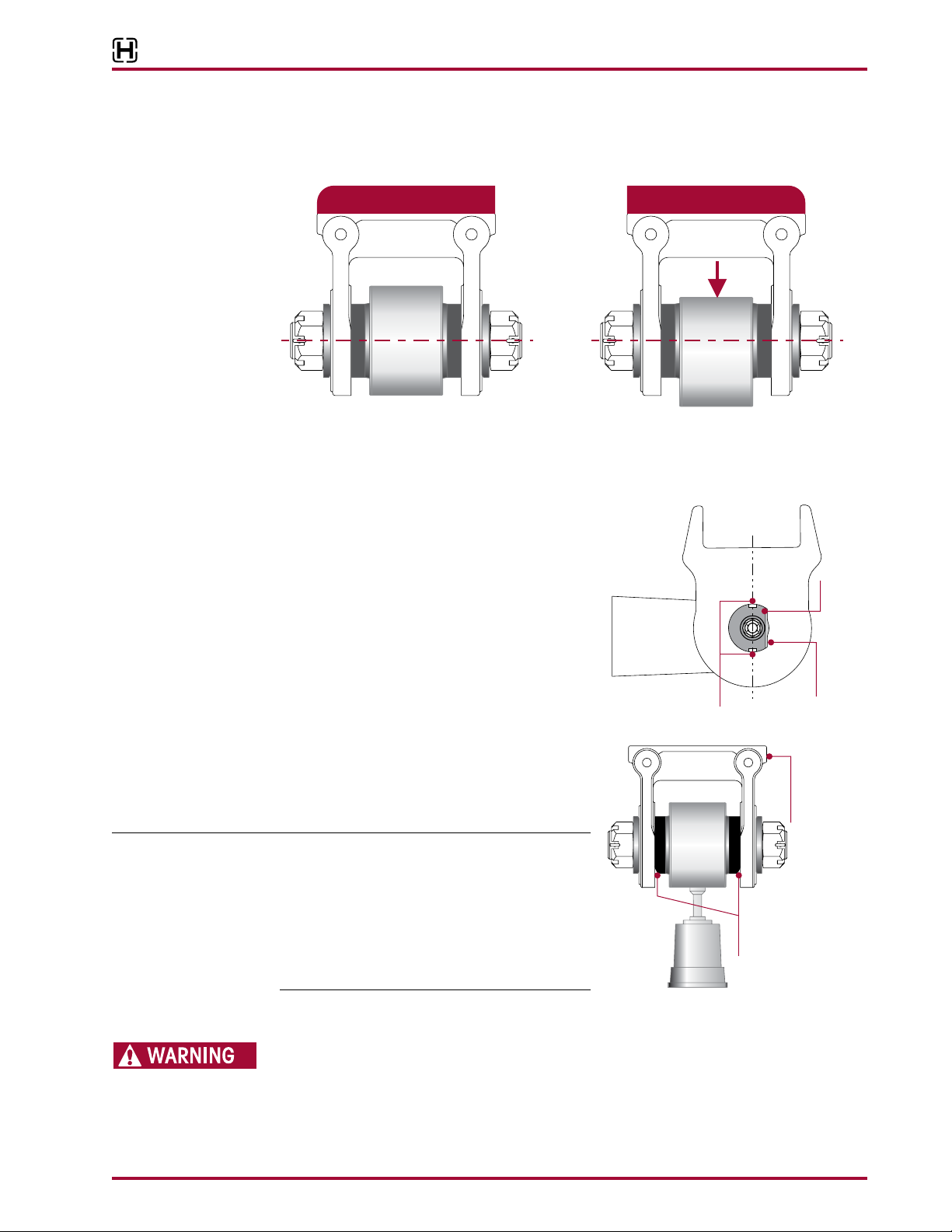
FIGURE 6-6
GOOD BUSHING
ULTIMAAX® for Fire and Rescue Vehicles
WORN BUSHING
Axle Bracket
C
L
A bushing will result in the equalizingGOOD
beam end hub appearing to be centered
with the centerline of the end bushing
FIGURE 6-7
A bushing will result in the equalizingWORN
beam end hub appearing to be /" (15 mm)
offset/below the centerline of the end bushing
3. The beam end adapter style connections have
the flange of the adapter cut off for assembly
clearance with the axle housing bowl.
■
The flat must be positioned vertically as
shown in Figure 6-7. If the flat of the adapter
position is incorrect, removal of the fasteners will be necessary to correct position,
Equalizing
Beam
refer to the Adapter Style End bushings in
the Component Replacement Section.
JACK TEST
FIGURE 6-8
1. Place a jack under each beam end as shown.
Raise the jack to check for movement in
the connection or rubber components, see
Figure6-8.
Axle Bracket
C
L
Axle Bracket
5
8
Adapter
Adapter
Vertical
Axle Bracket
Supplied by
Vehicle
Manufactur
NOTE The gap at each side of the visible rubber on the
lower part of the bar pin end bushing is normal,
see Figure6-8, and is not an indication to replace
the bushing. Because all rubber end bushings are
in compression, with the load bearing on the top
side, the lower side of the rubber is slightly relieved,
allowing the rubber to move inward, and a gap
Gap in rubber of
End Bushing
is normal
appears.
PHYSICAL INSPECTION
IF BUSHING MOVEMENT OR LOOSENESS IS NOTED IN THE EQUALIZING BEAM END HUB, DO NOT
17730-299 17 Preventive Maintenance
OPERATE THE VEHICLE. REPLACE THE RUBBER END BUSHINGS AND ALL CONNECTING PARTS.
THE ABOVE CONDITION CAN RESULT IN COSTLY REPAIR, DOWNTIME, POSSIBLE SEPARATION OF
COMPONENTS, ADVERSE VEHICLE HANDLING, PROPERTY DAMAGE, OR PERSONAL INJURY.
Page 18
ULTIMAAX® for Fire and Rescue Vehicles
ed Nut
Beam End Adapter
700 ± 50 ft.
ed.
Shim Type Bar Pin End Bushing
SERVICE HINT An equalizing beam end connection that is visibly cleaner than the other connections may indi-
cate a loose connection.
2. If bushing movement or looseness is detected in the equalizing beam end hub, DO NOT oper-
ate vehicle. Replace the equalizing beam end bushings and all connecting parts. Refer to the
Component Replacement Section of this publication.
3. Check and record torque values, see Figure 6-9. Correct torque values as required making
sure all fasteners are tightened to
torque.
FIGURE 6-9
63K ShownULTIMAAX
7
8
1/" Slotted Nut
Tightening Torque
125 ft. lbs. (170 Nm)
+ 90° rotation or
lbs.(949 ± 68 Nm)
125 foot pounds + 90° rotation or 700 ± 50 foot pounds
Equalizing Beam
Beam End Shaft
Adapter Style
End Bushing
Cotter Pin
7
8
1/" Slott
Beam End Adapter
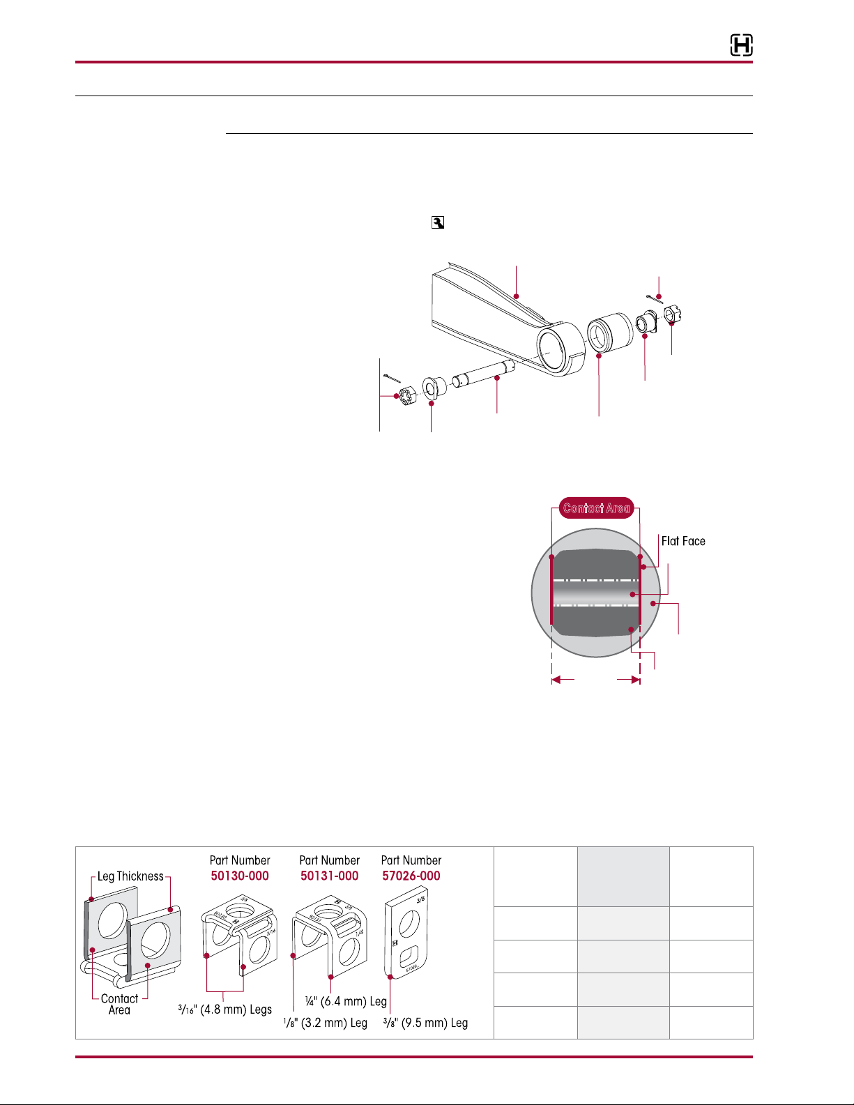
FIGURE 6-11
BAR PIN END BUSHINGS
FIGURE 6-10
VISUAL INSPECTION
An indication that the bar pin end bushing requires
replacement is when one or more of the following
conditions apply:
■
If the contact area, see Figure 6-10 (the flat face
area where bar pin contacts the axle bracket)
reveal signs of excessive wear. Replace if bar pin
thickness measures less than 17⁄8" (47.59mm).
■
If bar pin bolt holes bores reveal signs of elongation or wear, see Figure 6-10.
BAR PIN SHIMS
An indication that the bar pin shims require
replacement is when one or more of the following
conditions apply:
■
Visual inspection of contact area on the shim reveals signs of excessive wear.
■
The thickness of any single leg on the shim, is less than the measurement shown in
Figure6-11, replacement of bar pin shim is required.
Original
Thickness
of Shim Leg
Contact Area
Bolt Hole
Bore
Confinement
Washer
Bar Pin
1.874"
(47.59 mm)
If bar pin measurement is less than
1.874" (47.59 mm),replacement is requir
Minimum
Thickness
Required
Part Number
1
⁄8" (3.2 mm) 0.123" (3.1 mm) 50131-000
3
⁄16" (4.8 mm) 0.186" (4.7 mm) 50130-000
¼" (6.4 mm) 0.248" (6.3 mm) 50131-000
3
⁄8" (9.5 mm) 0.371" (9.4 mm) 57026-000
Preventive Maintenance 18 17730-299
Page 19
ULTIMAAX® for Fire and Rescue Vehicles
Typical location
of crack areas
8.5" ± 0.1"
(216 mm ± 2.6 mm)
Look for cracks
in these locations
2.29" ± 0.025"
(58.11 mm ± 0.63 mm)
NOTE: Typical axle
brackets shown
2½" (64 mm)
*Standard
Axle Bracket
(Rubber Bushing)
ADAPTER STYLE AXLE
*Typical axle bracket shown
Axle Bracket Leg
6.01/6.02"
(152.6/152.8 mm)
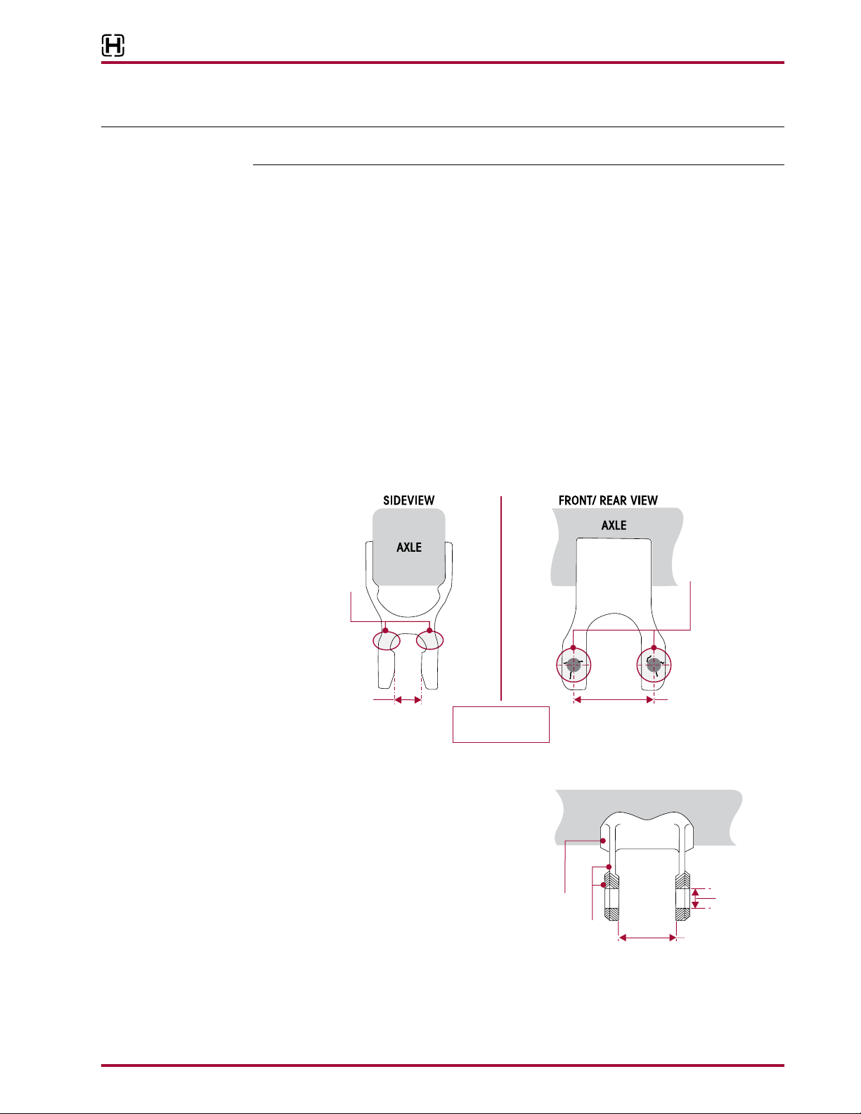
BEAM END AXLE BRACKETS
NOTE The axle brackets are furnished and welded into position by the vehicle manufacturer or axle
manufacturer.
VISUAL INSPECTION
When inspecting the equalizing beam end connection also inspect the axle brackets for damage
or cracks, see Figures 6-12, 6-13 and 6-14. Any axle bracket that is found damaged or cracked
must be repaired or replaced.
Consult the axle and/or vehicle manufacturer for additional inspections, component repair and
replacement instructions.
PHYSICAL INSPECTION
■
Bar Pin Style
a. Inspect the axle brackets for damage or cracks in the locations shown in Figures 6-12 and
6-13. Any axle bracket that is found damaged or cracked must be repaired or replaced.
b. Measure the distance between the axle bracket legs for correct width, refer to Figures
6-12 and 6-13 for measurement location and dimensions. An axle bracket outside of the
measurement range must be repaired or replaced.
c. Consult the vehicle manufacturer for inspection, component repair and replacement
instructions
FIGURE 6-12 FIGURE 6-13
17730-299 19 Preventive Maintenance
■
Adapter Style
FIGURE 6-14
a. Inspect the 2½" (64 mm)
b. Remove any burrs or material
c. Use a new adapter style bush-
d. Measure the distance
diameter holes in each of the
Axle
axle bracket legs, Figure6-14.
left there by the old adapters.
ing as a gauge for fit, being
sure it enters the holes from
the outside of each bracket leg.
between the axle bracket legs for correct width, refer to Figure 6-14 for measurement
location and dimensions. The dimension between the inside surfaces of the axle bracket
legs is 6.015" ± 0.005" (152.7 mm ± 0.1 mm), see Figure 6-14.
Page 20
ULTIMAAX® for Fire and Rescue Vehicles
s
the fr
Assembly
Shear Spring
Shear Spring
FRAME HANGER ASSEMBLY
The following points are for guidance and intended to assist personnel in determining when
frame hanger assembly maintenance is necessary.
INSPECTION
■
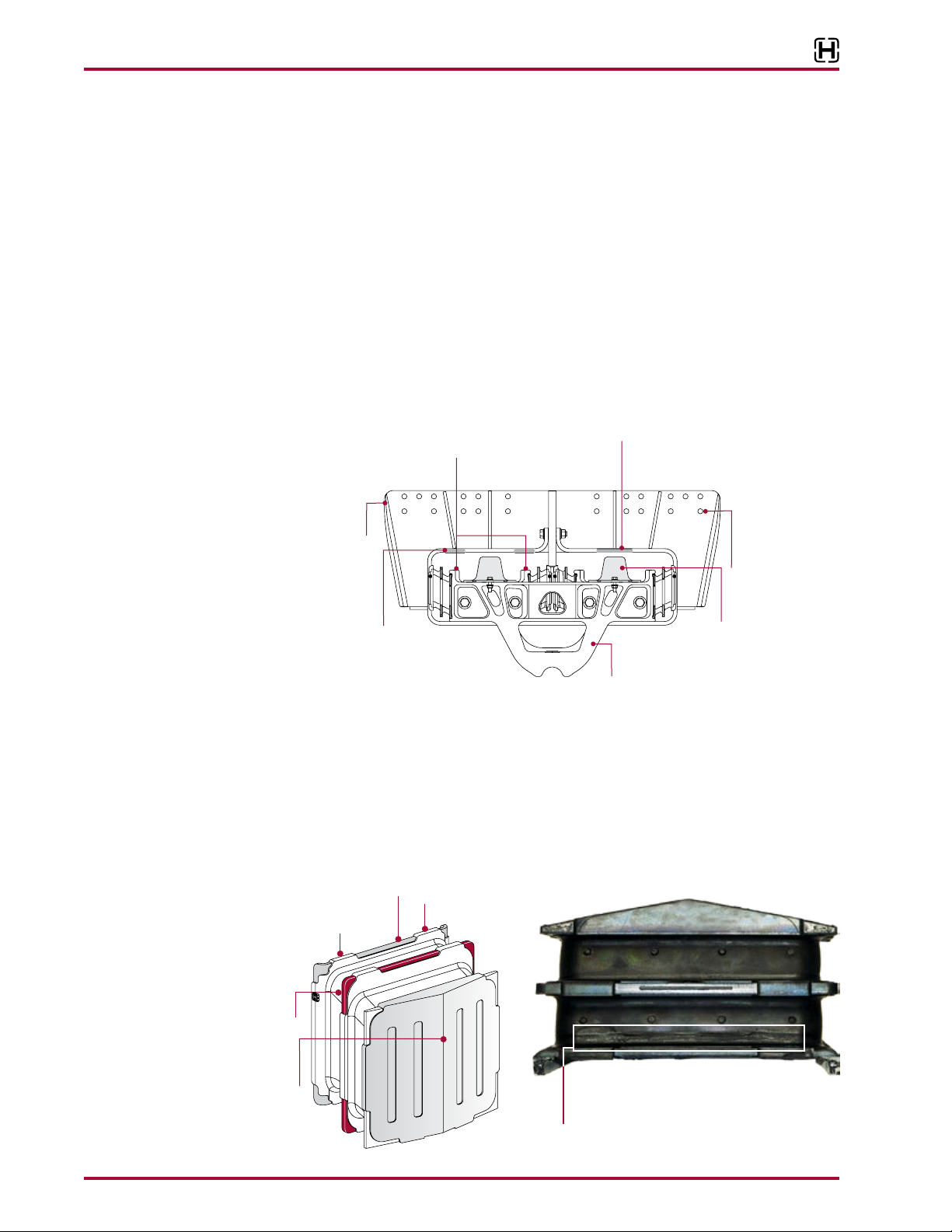
Inspect the frame hanger for any damage, cracks or signs of adverse or abrasive contact with
other components. Some minor wear will be evident where the progressive load spring contacts the frame hanger assembly, see Figure 6-15. If more than half the thickness of the frame
hanger plate is damaged or cracked, replace the frame hanger assembly.
■
Look for wear in the frame hanger cavity due to contact with the jounce stop, see Figure 6-15.
If more than half the thickness of the frame hanger plate is worn or damaged, replace the
frame hanger.
■
Inspect frame hanger attaching fasteners and frame hanger assembly for signs of looseness
or movement. Retighten any loose fasteners to specified torque. Components damaged by
loose fasteners must be replaced.
FIGURE 6-15
63K ShownULTIMAAX
Jounce Stops
Minor wear area between the
frame hanger plate and
progressive load spring
Frame Hanger
Wear area between
ame hanger plate
and jounce stops
Saddle
Location of
frame hanger
attaching fastener
Progressive
Load Spring
SHEAR SPRINGS
INSPECTION
Inspection of the shear spring should always be conducted with the vehicle in the UNLOADED
condition.
■
Bent or burred edges on the rate plates extending beyond the rubber are acceptable provided
the rubber can freely expand during vehicle operation, see Figure 6-16.
■
Creases formed by folding of the rubber surface under load are acceptable. These appear as
stripes on the surface, polished by wear or covered with tacky (sticky) rubber, see Figure6-17.
FIGURE 6-16 FIGURE 6-17
Flange Flat Side
Notch on To p
Notch on To p
Shear Spring
Rate Plate
Angled Side
Preventive Maintenance 20 17730-299
Polished Appearance — Creases formed by
the folding of the rubber surface under load
are acceptable.
Page 21
ULTIMAAX® for Fire and Rescue Vehicles
FIGURE 6-18
■
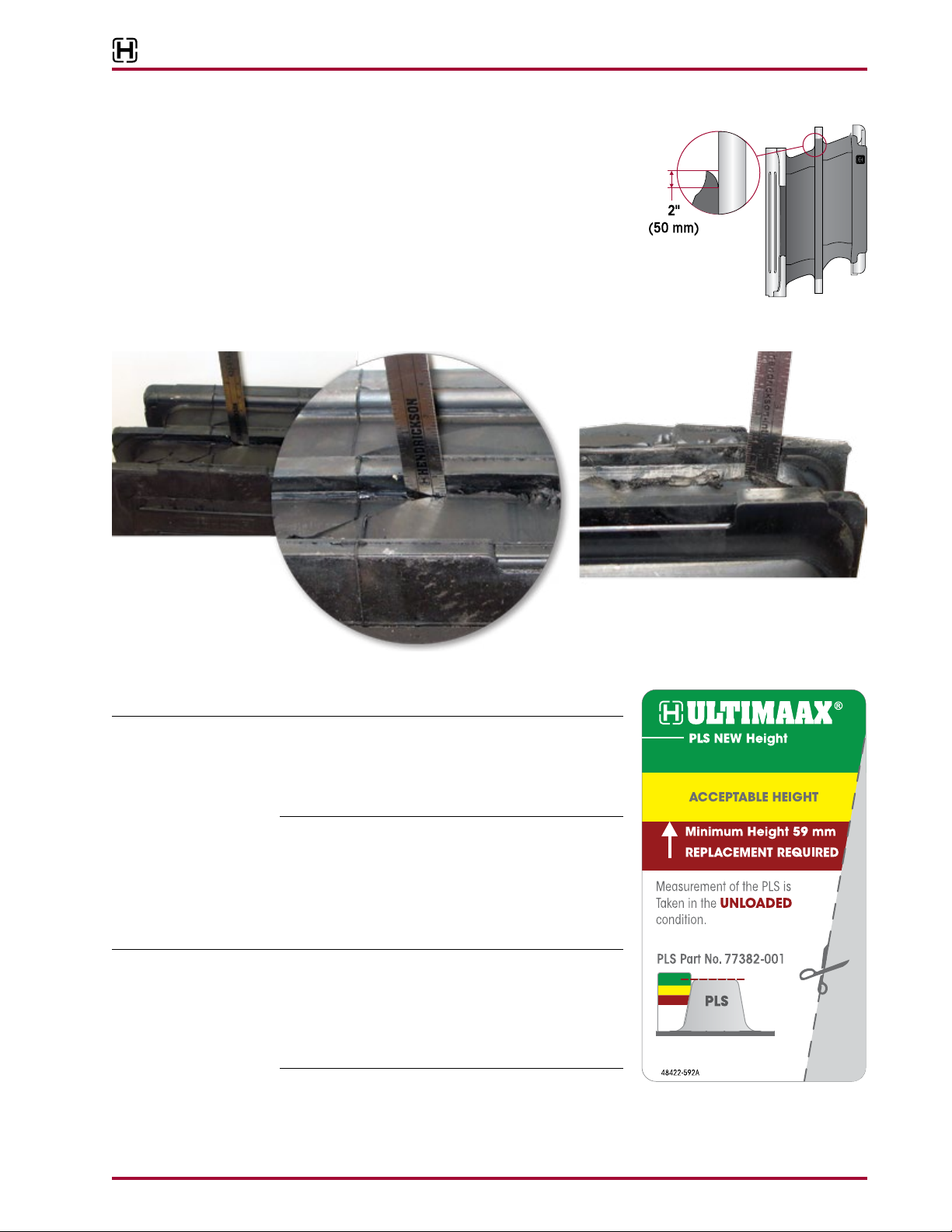
Bonding separation of the rubber from any of the
bonded rate plate surfaces to a maximum depth
of approximately 2" (50mm) is acceptable, see
Figure6-18. If the bonding separation depth is
2" (50mm) or more, the shear springs require
replacement.
■
A certain amount of gradual breakup of the rubber surface is acceptable. Use a feeler gauge to measure cuts
or splits in the rubber. If the measurement is over a
depth of 2" (50 mm), then the shear springs require replacement, see Figures 6-19 and6-20.
FIGURE 6-19 FIGURE 6-20
FIGURE 6-21
PROGRESSIVE LOAD SPRINGS (PLS)
NOTE Hendrickson Lit. No. 48422-592 – ULTIMAAX Gauge
Card (Figure 6-21) can be used to measure in the
unloaded condition the height of the progressive load
spring (PLS), plus the length of cuts / splits and depth of
separation of the shear spring and the PLS.
Visually inspect the progressive load springs at
regular preventive maintenance intervals. The following points are for guidance and intended to assist
personnel in determining when progressive load spring
component requires replacement, refer to the Component
Replacement Section of this publication.
NOTE The Hendrickson ULTIMAAX suspension progressive load
springs must be replaced in pairs (left side pairs or right
side pairs or rear position pairs or front position pairs),
even if only one PLS shows unacceptable conditions.
Replacement of only one PLS can cause uneven wear,
and higher premature wear for the one replaced
■
Always inspect the progressive load spring with the
vehicle in the UNLOADED condition.
■
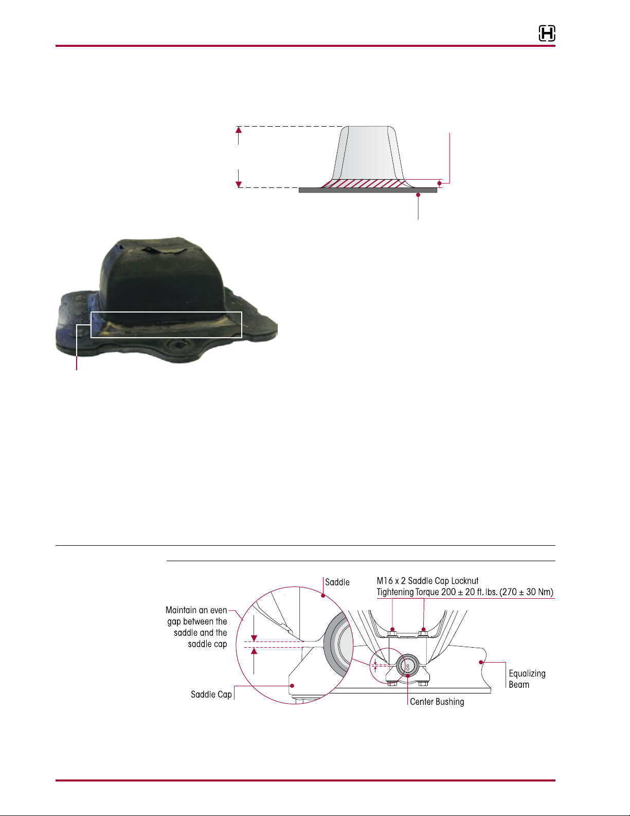
The height of a new PLS is 31⁄16" (78 mm). The PLS requires replacement if the height is below
25⁄16" (59 mm), see Figure 6-22.
17730-299 21 Preventive Maintenance
Page 22
ULTIMAAX® for Fire and Rescue Vehicles
Minimum accept
is less than 2.3" (59 mm)
Base
Creases formed by the folding of
the rubber surface under load are acceptable.
■
A bent or cracked mounting base requires PLS replacement.
FIGURE 6-22
PLS height when new 3.1" (78 mm)
able height 2.3" (59 mm)
Progressive Load Spring (PLS) Height
in the Unloaded Condition
Inspection area
for any cuts,
splits,or bonding
separation
FIGURE 6-23
Progressive Load Spring
Polished Appearance —
Replacement required if PLS height
■
If any cuts or splits in the rubber of over 2" (50 mm) in length
Mounting
and an average depth of ½" (13 mm), the effected PLS
requires replacement. A certain amount of gradual breakup
of the rubber surface is normal. The most probable areas for
potential cuts, splits, or wear are shown in Figure 6-22 as
“///////.”
■
The bonding separation depth of the rubber from the PLS
mounting base plate surface (see Figure 6-22) is more than
½" (13 mm), the effected PLS requires replacement.
■
Creases formed by folding of the rubber surface under load
are acceptable. These appear as stripes on the surface, polished by wear or covered with tacky rubber, see Figure 6-23.
SADDLE CONNECTION
Visually inspect for any signs of movement or looseness and ensure:
■
Each saddle is centered on each equalizing beam center bushing.
■
The center bushing inner metal is fully seated to the saddle.
■
Saddle cap locknuts are tightened to proper torque as specified in the Torque Specifications
Section of this publication.
Saddle cap fasteners — While tightening the saddle cap fasteners maintain an even gap
between the saddle and saddle cap, see Figure 6-24.
NOTE Tightening the saddle cap fasteners properly will help prevent wear of mating components.
Preventive Maintenance 22 17730-299
FIGURE 6-24
Page 23
ULTIMAAX® for Fire and Rescue Vehicles
CROSS TUBE
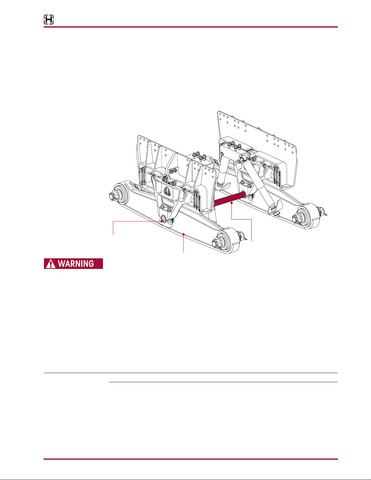
The ULTIMAAX cross tube connects the two (2) equalizing beams through the equalizing beam’s
center bushings, see Figure 6-25. The cross tube has clearance to float side-to-side in the center
bushings.
The length of the cross tube will allow side-to-side movement of approximately 2
this reason, the cross tube may appear polished or missing paint at each end where it enters
into the center bushings. This is normal. Also, the cross tube will rattle in straight position which
is acceptable.
FIGURE 6-25
63K ShownULTIMAAX
3
⁄8" (60mm). For
Center Bushing
greaseDO NOT
Equalizing
Beam
Cross Tube
grease or
DO NOT
use as a jacking point
IMPROPER JACKING METHODS CAN CAUSE STRUCTURAL DAMAGE WHICH CAN CAUSE ADVERSE
VEHICLE HANDLING, PROPERTY DAMAGE OR SEVERE PERSONAL INJURY AND WILL VOID
HENDRICKSON’S WARRANTY.
■
DO NOT USE THE SUSPENSION CROSS TUBE AS A JACKING POINT, REFER TO VEHICLE MANUFACTURER FOR PROPER JACKING INSTRUCTIONS.
■
ACCEPTABLE LIFTING POINTS FOR A VEHICLE AT THE RATED LOAD INCLUDE BUT NOT LIMITED
TO: THE AXLE, EQUALIZING BEAM, AND THE VEHICLE FRAME RAIL. REFER TO THE VEHICLE
MANUFACTURER FOR PROPER JACKING INSTRUCTIONS.
DO NOT grease or lubricate the cross tube or the center bushing and DO NOT use the cross tube
as a jacking point, see Figure 6-25.
VISUAL INSPECTION
■
Visually inspect the overall condition of the cross tube for dents, dings, or bent condition,
replace as necessary.
NOTE A bent cross tube may cause misalignment of the axles, which may cause abnormal tire wear.
■
Use a straight edge to inspect the straightness of the cross tube, replace as necessary.
17730-299 23 Preventive Maintenance
Page 24
ULTIMAAX® for Fire and Rescue Vehicles
TORQUE RODS
THE ULTIMAAX SUSPENSION INCORPORATES TORQUE RODS FOR VEHICLE STABILITY. IF THESE
COMPONENTS ARE DISCONNECTED OR ARE NON-FUNCTIONAL THE VEHICLE SHOULD NOT BE
OPERATED. FAILURE TO DO SO CAN RESULT IN ADVERSE VEHICLE HANDLING AND POSSIBLE TIRE
CONTACT WITH THE FRAME OR THE SUSPENSION.
Visually inspect torque rod bushings for any torn or shredded rubber, inspect for bent, cracked,
or broken torque rods, and for end hubs with any elongated “oval” shape. Any of these conditions
will require component replacement.
Torque rod looseness inspection is necessary per the following method below.
■
With the vehicle shut down, a lever check can be made with a long pry bar placed under each
rod end and pressure applied.
TORQUE ROD LENGTH
Longitudinal torque rod length is determined by the vehicle manufacturer for optimum drive-
line angles. The longitudinal torque rods maintain these angles and control acceleration and
brake forces.
Transverse torque rod length is also determined by the vehicle manufacturer to center the axles
under the frame.
■
If the lateral alignment of the axles is incorrect, it may be necessary to shim the transverse
torque rod at the straddle mount end. Shims can be installed between the transverse torque
rod and the transverse torque rod frame bracket or between the transverse torque rod and
axle tower bracket. Refer to vehicle manufacturer for proper shim location; also see Lateral
Alignment in the Alignment & Adjustments Section of this publication.
■
The transverse torque rods also control axle walk-out during cornering. The mounting brackets
at the axle housing end of the torque rods are furnished and welded into position on the axle
housings by the axle or vehicle manufacturer.
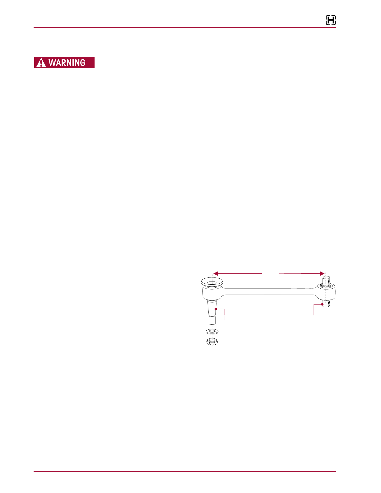
FIGURE 6-26
Transverse and longitudinal torque
rods have attaching ends desig-
nated as “straddle mount,” or “tapered
stud” as shown in Figure6-26. Most
can be replaced by pressing out the
worn torque rod bushing and install-
Tapered Stud
ing a replacement bushing, others
require complete torque rod assembly
replacement.
It is important that the tightening
torque of the nuts be checked during preventive maintenance service. Follow the vehicle manufacturer’s specifications for tightening torque values.
Length
Straddle Mount
The tapered stud torque rod locknuts also should be checked. Refer to the Torque Specification
Section of this publication for proper torque values.
Preventive Maintenance 24 17730-299
Page 25
ULTIMAAX® for Fire and Rescue Vehicles
SHOCK ABSORBERS
FIGURE 6-27
NOTE It is not necessary to replace shock absorbers in pairs
if one shock absorber requires replacement.
Hendrickson offers a long service life, premium shock
absorber for use on ULTIMAAX suspensions. If shock
absorber replacement is necessary, Hendrickson recommends that original Hendrickson shock absorbers
be replaced with identical Hendrickson Genuine
parts for servicing. Failure to do so will affect the
suspension performance, durability, and will void the
warranty.
Inspection of the shock absorber can be performed
by doing a heat test, and a visual inspection. For
instructions on shock absorber replacement see the
Component Replacement Section of this publication.
HEAT TEST
1. Drive the vehicle at moderate speeds on rough
road for minimum of fifteen minutes.
DO NOT GRAB THE SHOCK AS IT COULD POSSIBLY CAUSE PERSONAL INJURY.
2. Use an infrared thermometer to check the temperature of the shock absorber. This can also
be performed by carefully touching the shock body below the dust cover. Touch the frame to
get an ambient reference, see Figure 6-27. A warm shock absorber is acceptable, a cold shock
absorber should be replaced.
3. To inspect for an internal failure, remove and shake the suspected shock. Listen for the sound
of metal parts rattling inside. Rattling of metal parts can indicate that the shock has an internal failure.
VISUAL INSPECTION
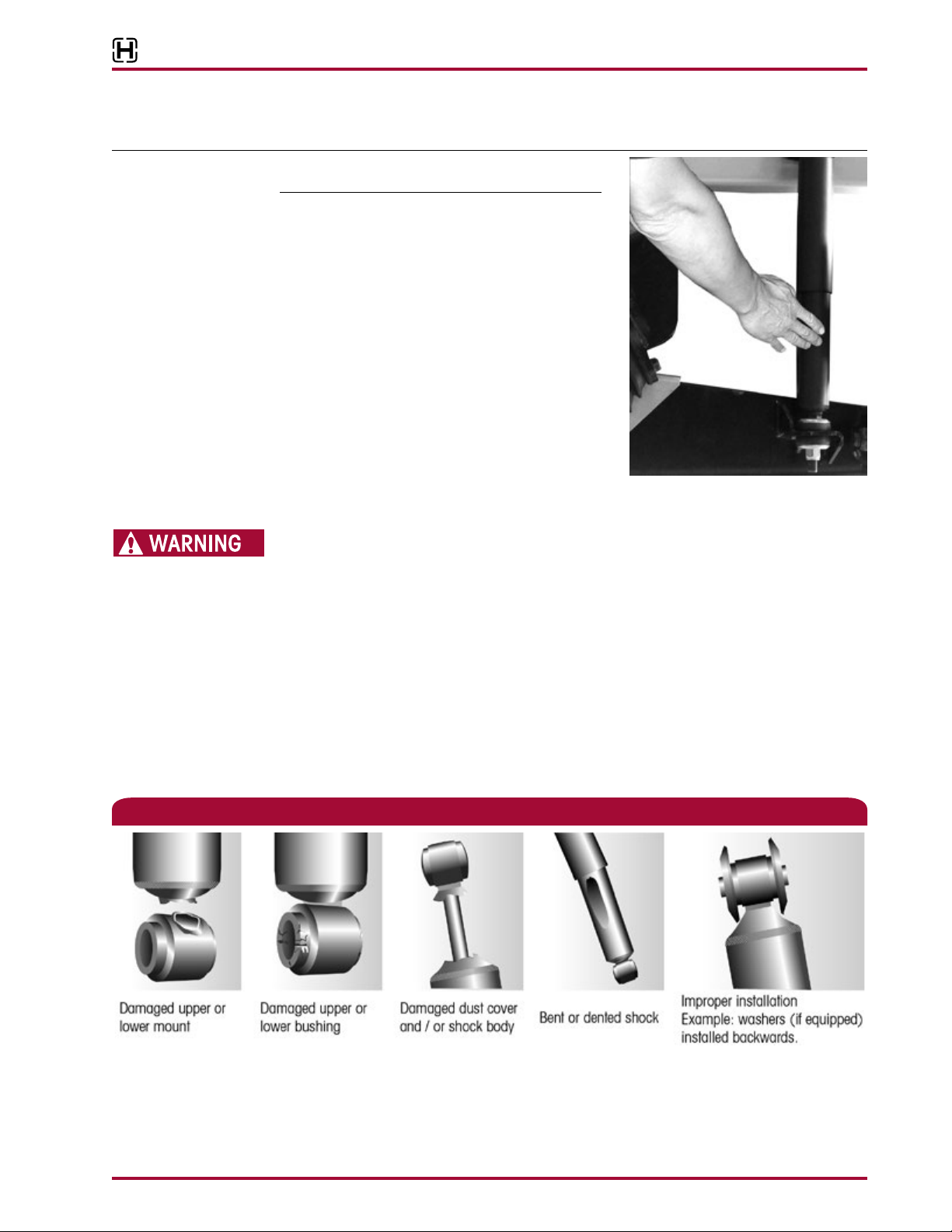
Look for any of the potential problems shown in Figure 6-28 when doing a visual inspection.
Inspect the shock absorbers fully extended. Replace as necessary.
FIGURE 6-28
SHOCK ABSORBER VISUAL INSPECTION - UNACCEPTABLE CONDITIONS
17730-299 25 Preventive Maintenance
Page 26
ULTIMAAX® for Fire and Rescue Vehicles
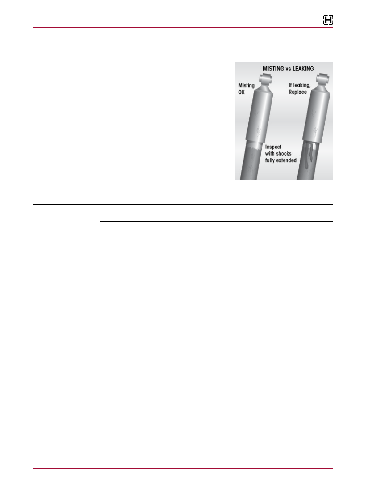
LEAKING VS. MISTING SHOCK VISUAL INSPECTION
FIGURE 6-29
The inspection must not be conducted after driving
in wet weather or a vehicle wash. Shocks need to be
free from water. Many shocks are often misdiagnosed
as failures. Misting is the process whereby very small
amounts of shock fluid evaporate at a high operating
temperature through the upper seal of the shock,
see Figure 6-29. When the “mist” reaches the cooler
outside air, it condenses and forms a film on the outside of the shock body. Misting is perfectly normal
and necessary function of the shock. The fluid, which
evaporates through the seal area helps to lubricate
and prolong the life of the seal.
A shock that is truly leaking and needs to be replaced
will show signs of fluid leaking in streams from the
upper seal. These streams can easily be seen when
the shock is fully extended, underneath the main
body (dust cover) of the shock. Look for these potential problems when doing a visual inspection.
Inspect the shock absorbers fully extended. Replace as necessary.
NOTE The ULTIMAAX suspension is equipped with a premium seal on the shock, however this seal will allow
for misting to appear on the shock body (misting is not a leak and is considered acceptable).
If the shock is damaged, install new shock absorber and replace as detailed in the Component
Replacement Section of this publication.
Preventive Maintenance 26 17730-299
Page 27
SECTION 7
Alignment & Adjustments
AXLE ALIGNMENT
■
The primary control for axle alignment is the location of the frame hanger assemblies on
the frame rail as installed by the vehicle manufacturer, and the location of the axle brackets
on the axles as installed by the axle or vehicle manufacturer.
■
Axle centering and pinion angles are controlled by the torque rods.
■
Ride height is controlled by the design of the suspension frame hanger. No adjustment is
possible.
DRIVE AXLE PINION ANGLE
Drive axle pinion angles are established by the vehicle manufacturer. If pinion angle adjustment
is required, check for proper angles with the vehicle manufacturer. Pinion angle is set by the longitudinal torque rod length.
TO CHECK THE PINION ANGLE
FIGURE 7-1
1. Use a work bay with a level
floor.
2. Relax the suspension by
slowly moving the vehicle
back and forth several times
in a straight line without using
the brakes. This will slacken or
loosen the suspension as the
vehicle is positioned. End with
all wheels positioned straight
ahead. Roll to a stop without
the brakes being applied. DO NOT set the parking brake.
3. Chock the front wheels of the vehicle.
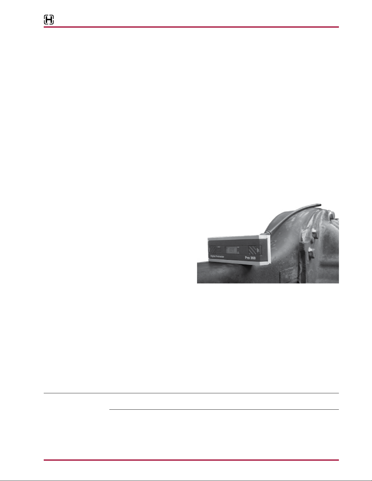
4. Place a digital protractor on the axle housing as shown in Figure 7-1.
5. Check to see if the pinion angle is correct per the vehicle manufacturer’s specified range.
6. If necessary, add/remove shims at the longitudinal torque rod connections as required to
achieve the proper pinion angle.
7. When the pinion angle is correct tighten all fasteners to the proper torque specifications per
the vehicle manufacturer and recheck the pinion angles.
8. Remove wheel chocks.
ULTIMAAX® for Fire and Rescue Vehicles
DRIVE AXLE ALIGNMENT
NOTE Drive axle alignment with suspensions equipped with adapter style equalizing beam end con-
nections ARE NOT adjustable.
Computerized alignment equipment is the preferred method of measuring alignment. To calculate
the shim thickness required, the target offset must be converted to thrust angle, see alignment
equipment manufacturer for procedures. If, however, computerized axle alignment equipment is
not available refer to the following Inspection in this section.
17730-299 27 Alignment & Adjustments
Page 28
ULTIMAAX® for Fire and Rescue Vehicles
Proper alignment is essential for maximum ride quality, performance, and tire service life. The following recommended alignment procedure as described below, should be performed if excessive
or irregular tire wear is observed.
NOTE Proper vehicle alignment can only be achieved when all axles are aligned to the vehicle’s
centerline and the steering axle’s caster, camber and toe-in settings are within specifications.
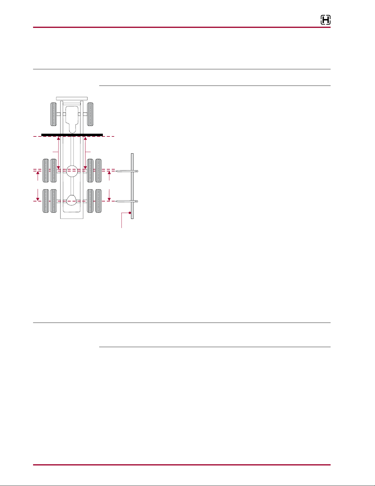
FIGURE 7-2
AB
C
Trammel
9. Using a measuring tape, measure from the straight edge to the forward face of the front drive
10. Calculate the difference between measurements A and B.
▲
FRONT
D
Bar
axle arms on both sides of the vehicle as shown in Figure 7-2, dimensions A and B.
a. If the front drive axle is within vehicle manufacturer’s specifications, proceed to check the
rear drive axle (Step 11).
b. If alignment of the front drive axle IS NOT within the vehicle manufacturer’s specifications,
then the alignment of this axle MUST be corrected BEFORE measuring the rear drive axle
alignment (Step 11).
c. If the suspension is equipped with bar pin end bushings, correct the alignment of this axle
by following the bar pin alignment instructions in this section.
INSPECTION
1. Use a work bay with a level, flat surface.
2. Relax the suspension by slowly moving the vehicle back and forth several
times in a straight line. This will slacken or loosen the suspension as the
vehicle is positioned. End with all wheels positioned straight ahead.
3. DO NOT set the parking brake. Chock the front wheels of the vehicle.
4. Verify the vehicle system air is at full operating pressure.
5. Verify all suspension components are in good condition. Repair or replace
any worn or damaged suspension components before proceeding with the
alignment process.
6. Ensure all drive axle tires are at the same size.
7. Securely clamp a six-foot piece of STRAIGHT bar stock or angle iron across
the lower frame flange as shown in Figure 7-2. Select a location for the bar
stock or angle iron as far forward of the drive axle as possible where components will not interfere.
8. Accurately square the bar stock or angle iron to the frame using a carpenter’s square.
NOTE Since the remaining drive axle will be aligned relative to the front drive axle, it is essential that the
front drive axle is aligned within the vehicle manufacturer’s specifications prior to the alignment
of the remaining drive axle.
11. Using a trammel bar, measure the distance from the spindle center of the front drive axle to the
spindle center of the rear drive axle on both sides of the vehicle; see Figure 7-2, C and D.
12. Calculate the difference between measurements C and D.
a. If the measurements are within the vehicle manufacturer’s specifications, then the rear
drive axle alignment is acceptable.
b. If alignment of the rear drive axle IS NOT within the vehicle manufacturer’s specifications,
then the alignment of this axle MUST be corrected.
c. If the suspension is equipped with bar pin end bushings, correct the alignment of this axle
by following the Bar Pin with Shims Alignment instructions in this section.
13. Recheck measurements to confirm adjustments. Repeat Steps 10 through 12 until the correct
alignment is achieved.
14. After all drive axles are aligned, check the pinion angle of each drive, refer to the Axle Pinon
Angle in this section.
Alignment & Adjustments 28 17730-299
Page 29
ULTIMAAX® for Fire and Rescue Vehicles
AXLE LATERAL ALIGNMENT
1. Use a work bay with a level floor.
2. Drive the vehicle slowly, straight ahead. Try to slacken or loosen the suspension as the vehicle
is positioned. End with all wheels positioned straight ahead. Try to roll to a stop without the
brakes being used. DO NOT set the parking brake.
3. Chock the front wheels of the vehicle.
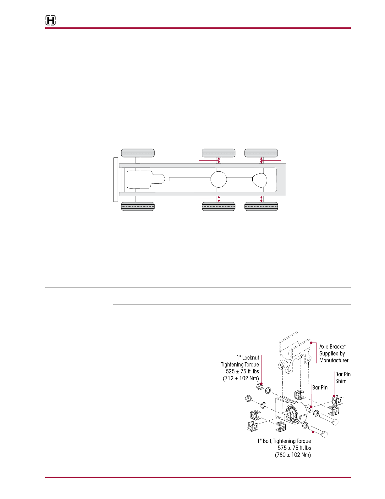
4. Measure from the outside of the frame rail to the rim flange of the inner tire. Record the measurement A and B, see Figure 7-3.
5. Measure the same distance on the opposite side of the same axle. Record the measurement
C and D, see Figure 7-3.
FIGURE 7-3
FRONT
▲
A
B
C
D
6. Verify the axle lateral alignment is within the vehicle manufacturer’s specifications. Adding
or removing shims that are located between the transverse torque rod and the frame rail will
normally correct the axle lateral alignment.
■
A general rule of thumb is to use a torque rod shim with a thickness that is half of the difference between the two measurements.
EXAMPLE If the axle lateral alignment is out of specification by ¼" (6mm), remove or install a
1
⁄8" (3 mm)
torque rod shim between the transverse torque rod and frame rail as needed. Refer to Longitudinal
and Transverse Torque Rod Section in Preventive Maintenance Section of this publication.
NOTE Hendrickson recommends the use of Grade 8 bolts and Grade C locknuts. Washers are not neces-
sary when flanged fasteners are used.
BAR PIN ALIGNMENT
FIGURE 7-4
The alignment feature consists of specially designed, tightly tolerance steel
shims which fill the 3⁄8" (9.5 mm) total
gap between the bushing’s bar pin and
the axle bracket legs. The gap must be
filled by placing the shims on the bushing
assembly in one of the positions shown
in Figure 7-4. Hendrickson has three shim
designs options for alignment, part number 50130-000 (provided), 50131-000
and 57026-000, see Figure 7-7.
17730-299 29 Alignment & Adjustments
Page 30
ULTIMAAX® for Fire and Rescue Vehicles
A BAR PIN SHIM MUST BE INSTALLED AT EACH BOLT LOCATION. THE SAME PART NUMBER SHIM IN THE
SAME ORIENTATION MUST BE USED AT BOTH BOLT LOCATIONS ON ANY ONE END BUSHING. DO NOT
INSTALL OR STACK MORE THAN ONE SHIM AT EACH BOLT LOCATION. USE GENUINE HENDRICKSON BAR
PIN SHIMS, DO NOT USE STANDARD WASHERS. FAILURE TO FOLLOW THESE WARNINGS MAY RESULT IN
IMPROPER VEHICLE ALIGNMENT, FRACTURE OF THE AXLE BRACKET OR BAR PIN WHICH COULD RESULT
IN THE ADVERSE VEHICLE HANDLING AND POSSIBLE PERSONAL INJURY OR PROPERTY DAMAGE.
ALIGNMENT ADJUSTMENT
FIGURE 7-5
If alignment of the drive axles is required, as determined by an
alignment inspection procedure, the following steps will need
to be performed.
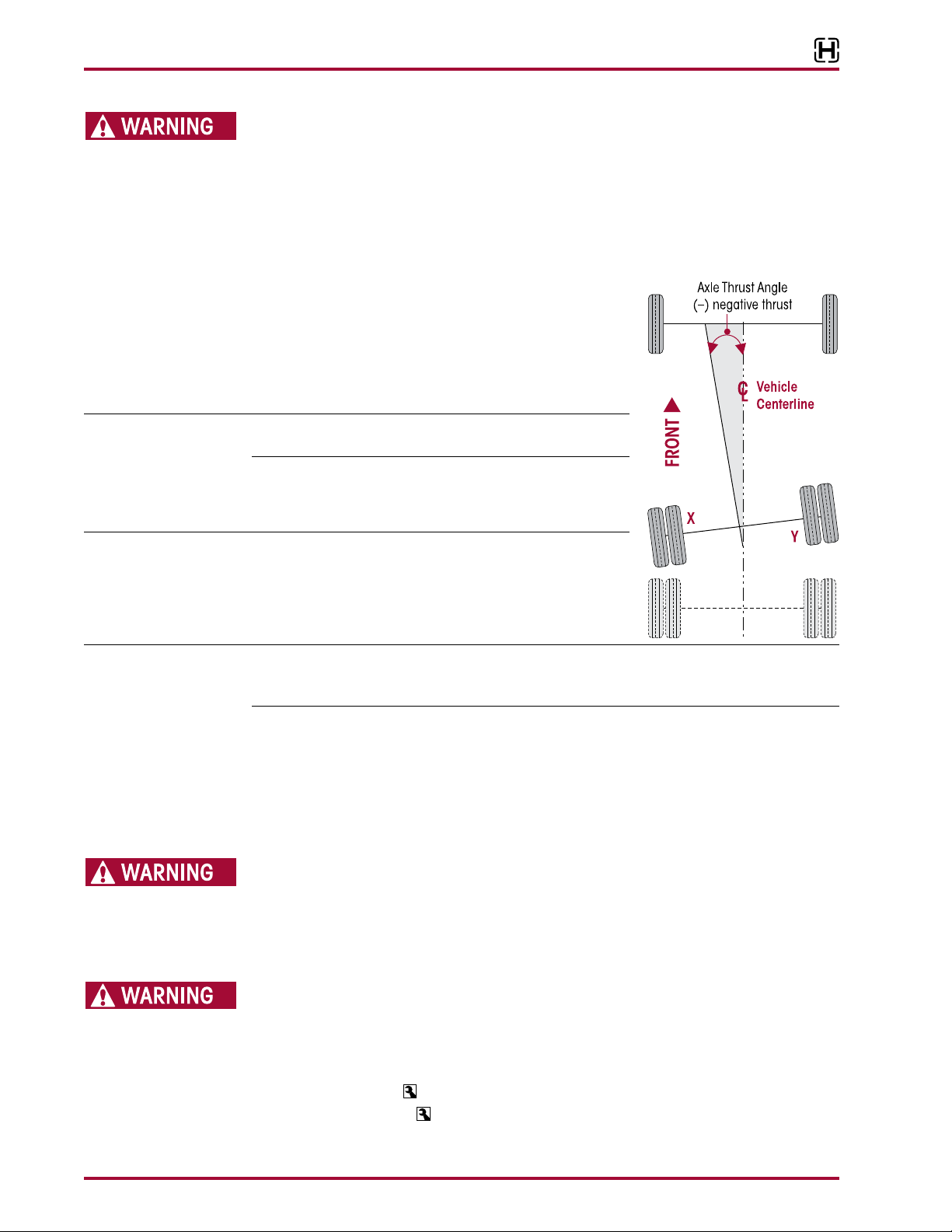
1. Determine direction of axle thrust angle. Figure 7-5 illustrates the forward drive axle with a thrust angle to the left
(-negative thrust).
SERVICE HINT Axle movement is in the same direction as the increased shim
thickness, see Figure 7-6.
2. To determine where to adjust shim thickness use measurement AandB for front drive axle or C and D for rear drive
axle, see Figure 7-1.
SERVICE HINT Axle adjustment will be on the side of the bar pin where shim
thickness is increased. For example, to correct the axle thrust
angle illustrated in Figure 7-5, shim thickness will need to be
increased at the front of the bar pin (Location X) and/or the
rear of the bar pin (Location Y).
NOTE Computerized alignment equipment is the preferred method of measuring alignment. To calculate
the shim thickness required the target offset must be converted to thrust angle, see alignment
equipment manufacturer for procedures.
3. Chock the wheels of the front axles to prevent vehicle movement during service.
4. Raise the frame of the vehicle to remove the load from the suspension. Support the frame at
this height.
5. Support the equalizing beam and remove the fasteners from the end bushing where the bar
pin alignment shim adjustment is being made.
6. Adjust shim thickness to move the axle in the desired direction, see Figure 7-6.
EACH EQUALIZING BEAM END BUSHING HAS ONE INBOARD AND ONE OUTBOARD ALIGNMENT SHIM,
FOR A TOTAL OF FOUR SETS OF TWO ALIGNMENT SHIMS PER SUSPENSION. EACH SET OF ALIGNMENT
SHIMS FOR A PARTICULAR BEAM END BUSHING MUST BE INSTALLED IN THE SAME ORIENTATION. SHIM
ORIENTATION MAY DIFFER FOR EACH BEAM END BUSHING, SEE FIGURE 7-4. FAILURE TO FOLLOW THESE
WARNINGS MAY RESULT IN THE FRACTURE OF EITHER THE AXLE BRACKET OR BAR PIN WHICH COULD
RESULT IN THE ADVERSE VEHICLE HANDLING AND POSSIBLE PERSONAL INJURY OR PROPERTY DAMAGE.
THE BAR PIN ALIGNMENT SHIM (PART NO. 50130-000) MUST BE INSTALLED WITH THE FOLDED EDGE
FACING AWAY FROM THE BUSHING, SEE FIGURE 7-7. FAILURE TO DO SO MAY RESULT IN SHIM DAMAGE,
IMPROPER ALIGNMENT, DAMAGE OR FRACTURE OF THE AXLE BRACKET OR BAR PIN WHICH COULD
RESULT IN THE ADVERSE VEHICLE HANDLING AND POSSIBLE PERSONAL INJURY OR PROPERTY DAMAGE.
7. Install new end bushing fasteners and tighten to:
■
At the locknut to 525 ± 75 foot pounds torque, or
■
At the bolt head to 575 ± 75 foot pounds torque
Alignment & Adjustments 30 17730-299
Page 31
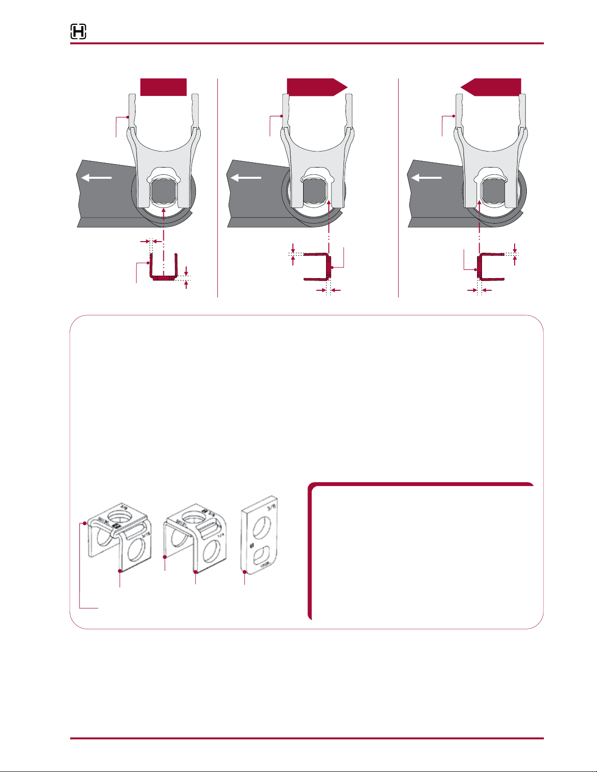
FIGURE 7-6
" (4.8 mm)
/ (9.5 mm)"
Nominal
ULTIMAAX® for Fire and Rescue Vehicles
Axle Moves
Axle Moves
Axle
Bracket
Equalizing
Beam
Center
3
16/ " (4.8 mm)
Alignment
Bar
Pin
Axle
Bracket
Equalizing
Beam
Center
3
16/ " (4.8 mm)
Bar
Pin
Alignment
Shim
Axle
Bracket
Equalizing
Beam
Center
Alignment
Shim
Shim
3
8
3
"
8/ (9.5 mm)
3
"
8/ (9.5 mm)
FIGURE 7-7
BAR PIN ALIGNMENT SHIMS
The following service notes will help when performing Hendrickson equalizing beam bar pin alignment
The standard alignment shims supplied with each
suspension (P/N 50130-000) have two/ " (4.8 mm) legs
3
and a/" (9.5 mm) back. Rotating the shim pairs 90° will
8
change the axle alignment in ±/ " (4.8 mm) increments.
If a finer adjustment is required use alignment shim (P/N
50131-000).This alignment shim has one /" (3.2 mm) leg,
3
one ¼" (6.4 mm) leg,and a/" (9.5 mm) back.A total of ¾"
8
(19 mm) adjustment is achievable to the axle.A /" (9.5 mm)
3
16
3
16
1
8
3
8
flat shim is also available (P/N 57026-000).
Part Number
50130-000
1
3
/ (4.8 mm) Legs
"
16
NOTE: Folded edge in 50130-000 shim
must be positioned away from the bushing
/ (3.2 mm) Leg"
8
Part Number
50131-000
¼" (6.4 mm) Leg
Part Number
57026-000
3
/" (9.5 mm) Leg
8
1
(1.5 mm) shim thickness increases thrust angle
/"
16
by 0.10".
To accomplish a thrust angle adjustment rotate the
alignment shims on the bar pin of the end bushing.
Axle movement will be in the direction of the shim
thickness increase.
Axle thrust angle may be adjusted at either wheel end
on an axle.If insufficient adjustment is available at
one wheel end, the opposing wheel end will also
need to be adjusted, but in the opposite direction.
Example: The alignment equipment shows the front drive
axle to have a 0.40° thrust angle to the left.This will
require a ¼" (6.4 mm) shim thickness increase to the
front side of the left front equalizing beam end bushing.If
there is less than ¼" (6.4 mm) of adjustment available at
this location then some of the adjustment will have to be
made at the rear of the right front end bushing.In this
1
case a/" (3.2 mm) shim thickness increase at the front
side of the left front bar pin a/" (3.2 mm) shim
8
1
AND
8
thickness increase at the rear side of the right front bar
pin will correct the 0.40° thrust angle.
Bar
Pin
3
/
16
8. Remove support and lower the vehicle.
9. Verify the axles’ alignments are within the vehicle manufactures tolerance.
10. Set brakes and remove wheel chocks.
17730-299 31 Alignment & Adjustments
Page 32
ULTIMAAX® for Fire and Rescue Vehicles
(109 ± 14 Nm)
M16 Upper Shock Br
SECTION 8
Component Replacement
FASTENERS
When servicing an ULTIMAAX suspension, Hendrickson recommends replacing all removed fasteners with new equivalent fasteners. Maintain correct torque values at all times. Check torque
values as specified, see Hendrickson’s Torque Specifications Section of this publication. If
non-Hendrickson fasteners are used follow torque specifications listed in the vehicle manufacturer’s service manual.
NOTE Torque values shown in this publication apply only if Hendrickson supplied fasteners are used. If
non-Hendrickson fasteners are used, follow the torque specifications listed in the vehicle manufacturer’s service manual.
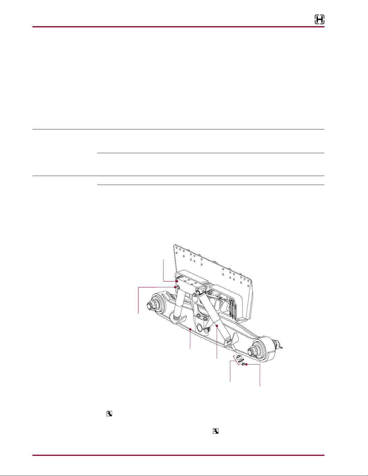
SHOCK ABSORBER
NOTE It is not necessary to replace shock absorbers in pairs if one shock absorber requires replacement.
DISASSEMBLY
1. Chock the front wheels of the vehicle.
2. Remove the lower shock absorber nylon locknut, retainer washer and rubber bushing from the
shock absorber stud, see Figure 8-1.
3. Remove the fasteners from the upper shock bracket and remove shock absorber.
FIGURE 8-1
63K ShownULTIMAAX
acket Fasteners
Tightening Torque
170 ± 20 ft. lbs. (231 ± 27 Nm)
Upper
Shock Bracket
Equalizing Beam
with Shock Bracket
Shock Absorber
Retaining Washer
and Bushing
5
/" Locknut
8
Tightening Torque
80 ± 10 ft. lbs.
ASSEMBLY
1. Mount the shock absorber in the upper shock bracket and install fasteners, tighten to
170±20 foot pounds torque, see Figure 8-1.
2. Locate the shock absorber stud in the lower shock bracket and install the rubber bushing,
retainer washer and nylon locknut. Tighten to
3. Remove the wheel chocks.
Component Replacement 32 17730-299
80 ± 10 foot pounds torque, see Figure 8-1.
Page 33
ULTIMAAX® for Fire and Rescue Vehicles
M16 Saddle Cap
SaddleSaddle Cap
Saddle Disassembl
Hendrickson
Hendrickson Part No. 66086-113L
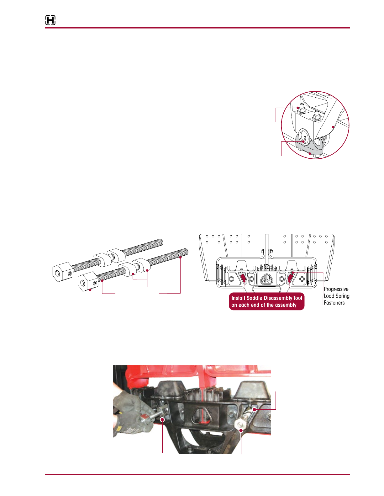
SHEAR SPRING / FRAME HANGER ASSEMBLY / SADDLE ASSEMBLY
You will need:
■
Saddle Disassembly Tool No. 66086-113L and Saddle Assembly Tool No. 66086-108L,
refer to the Special Tools Section of this publication.
FIGURE 8-2
DISASSEMBLY
1. Chock the front wheels of the vehicle.
2. Raise and support the drive axles.
3. Remove the drive tires from the side of the
vehicle being serviced.
4. Remove and discard the M16 saddle cap
fasteners that attach the saddle assembly to
the center bushing, see Figure 8-2.
5. Raise the vehicle’s frame just enough to create a ½" (13 mm) gap between the saddle assembly and center bushing. Support the vehicle’s frame at this height.
6. Remove the progressive load springs M10 fasteners and discard, see Figure8-4.
7. Remove the progressive load springs.
8. Apply NLGI #2–EP (Extreme Pressure) chassis lubricant to the threaded rod of the saddle
disassembly tool, No. 66086-113L, see Figure 8-3.
FIGURE 8-3 FIGURE 8-4
yTool
Part No.66086-113L
Fasteners
Center
Bushing
Blocking
Nuts
Apply #2–
Threaded
Rod Nut
(Extreme Pressure) chassis lubricant
NLGI EP
NOTE The threaded rod spacer and spacer nut are designed and orientated to fit into the saddle assem-
bly openings, see Figure 8-5.
9. Install both saddle disassembly tools on each end of one saddle assembly, rotate the threaded
rod blocking nuts until each are oriented properly into the saddle assembly openings, see
Figures 8-4 and 8-5.
FIGURE 8-5
Saddle Assembly
Opening
Threaded Rod
Blocking Nuts
Saddle Disassembly Tool
17730-299 33 Component Replacement
Page 34
ULTIMAAX® for Fire and Rescue Vehicles
lbs (440 Nm)
ation,
complete remove tape.
SERVICE HINT Use a rachet strap attached to each saddle half and the frame or vehicle body to secure the
saddle halves during removal.
10. Snug the saddle disassembly tool.
NOTE The shear springs are in each frame hanger are compressed when installed.
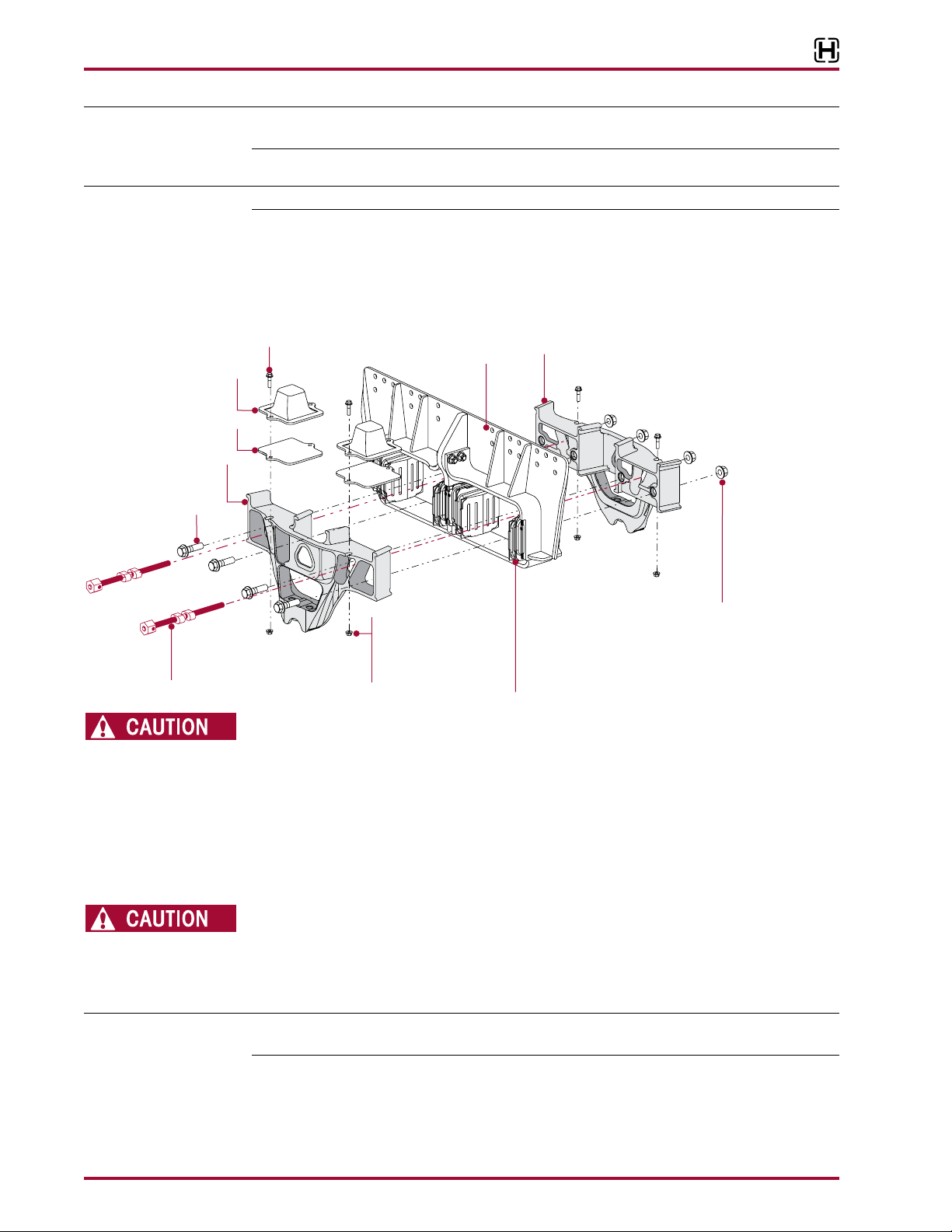
11. Remove and discard the M20 saddle fasteners, see Figure 8-6.
12. To separate the two saddle halves, evenly rotate the threaded rod nut to tighten the saddle
disassembly tool, see Figure8-6.
13. Remove the saddle halves and / or shear springs for replacement.
FIGURE 8-6
M10 Flange Bolt
Progressive Rate
Spring
Spacer (if equipped)
Saddle Assembly Half
(Outboard)
M20 Flange Bolt
Saddle DisassemblyTool
Part Number 66086-113L
63K ShownULTIMAAX
Frame Hanger
M10 Flange Locknut
Tightening Torque
30 ± 2 ft. lbs
(41 ± 3 Nm)
Saddle Assembly Half
(Inboard)
Shear Spring
During assembly, it
NOTE:
may be necessary to use tape
to hold the shear spring in
position.After installation is
M20 Flange Locknut
Tightening Torque
325 ft.
a 90° rot
PLUS
560 ± 30 ft. lbs
OR
(760± 40 Nm)
EACH FRAME HANGER ASSEMBLY WEIGHS APPROXIMATELY 104 TO 140 POUNDS (47 TO 63
KILOGRAMS), USE APPROPRIATE LIFTING DEVICES TO REMOVE OR INSTALL THE FRAME HANGER
ASSEMBLY. FAILURE TO DO SO CAN RESULT IN DAMAGE TO THE VEHICLE OR PERSONAL INJURY.
14. If replacing the frame hanger, remove the frame fasteners per the vehicle manufacturer’s
instructions. Remove frame hanger.
ASSEMBLY
1. If installing a new frame hanger continue to Step 2. If installing or servicing shear springs or
saddle assembly , proceed to Step 3.
EACH FRAME HANGER ASSEMBLY WEIGHS APPROXIMATELY 104 TO 140 POUNDS (47 TO 63
KILOGRAMS), USE APPROPRIATE LIFTING DEVICES TO REMOVE OR INSTALL THE FRAME HANGER
ASSEMBLY. FAILURE TO DO SO CAN RESULT IN DAMAGE TO THE VEHICLE OR PERSONAL INJURY.
2. Position the frame hanger assembly against the frame rail. Install fasteners per the vehicle
manufacturer’s instructions.
SERVICE HINT During assembly, it may be necessary to use tape to hold the shear springs in position. After instal-
lation is complete remove tape.
3. Position the shear springs with the flanged flat side against the frame hanger with the shear
spring angled downward, see Figure 8-7.
Component Replacement 34 17730-299
Page 35
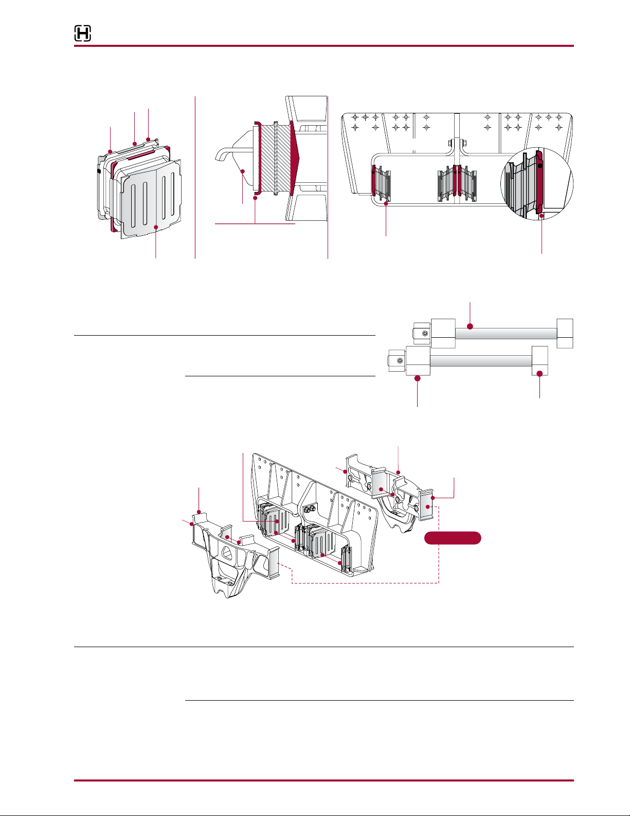
FIGURE 8-7
Flange Flat Side
SHEAR SPRING
63K ShownULTIMAAX
Saddle AssemblyTool
Hendrickson
y
Saddle
63K ShownULTIMAAX
Lubrication
ULTIMAAX® for Fire and Rescue Vehicles
Notch
on To p
Notch
on To p
Angled
Side
TOP VIEW
Frame
Hanger
Position shear springs
anged at side against
the frame hanger
FIGURE 8-8
SIDE VIEW
4. Apply NLGI #2–EP (Extreme Pressure) chassis lubricant to the threaded rod of the
Saddle Assembly Tool No. 66086-108L, see
Figure 8-8.
NOTE The threaded rod spacer and spacer nut are
designed and orientated to fit into the saddle
assembly openings, see Figure 8-10.
5. Apply P-80 lubricant to the shear spring’s
angled face and to the mating face of the
saddle halves, see Figure 8-9.
FIGURE 8-9
Frame Hanger
Shear Springs
Angled downward
Part No. 66086-108L
Threaded Rod
Spacer
Shear Springs
Flanged Flat Side
Apply #2–NLGI EP
Chassis Lubricant
Threaded Rod
Threaded Rod
Threaded Rod
Spacer Nut
Shear Spring
Angled Face Area
Assembly Half
(Outboard)
Saddle Assembly Half
(Inboard)
Mating faces of
Saddle Assembly
Apply P-80 lubricant to the angled
face area of the Shear Springs and
mating faces of the Saddle Assembl
6. On each side of one saddle assembly, rotate the threaded rod spacers and spacer nuts of the
saddle assembly tool until each are oriented properly into the saddle assembly openings, see
Figure 8-10.
SERVICE HINT Use a mechanism to attach to the frame to aid in holding the saddle up while performing pro-
cedure (such as a strap or rope) attached to each saddle half and the frame or the vehicle body
to secure the saddle halves during installation or have an additional person assist to align the
saddle halves properly.
7. Position the inner saddle half into the frame hanger along with the shear springs, outer saddle
half and the saddle assembly tool, see Figure 8-11.
8. Bring both saddle halves together with the saddle assembly tool. Evenly tightening the saddle
assembly tool until both saddle halves are seated against each other.
17730-299 35 Component Replacement
Page 36
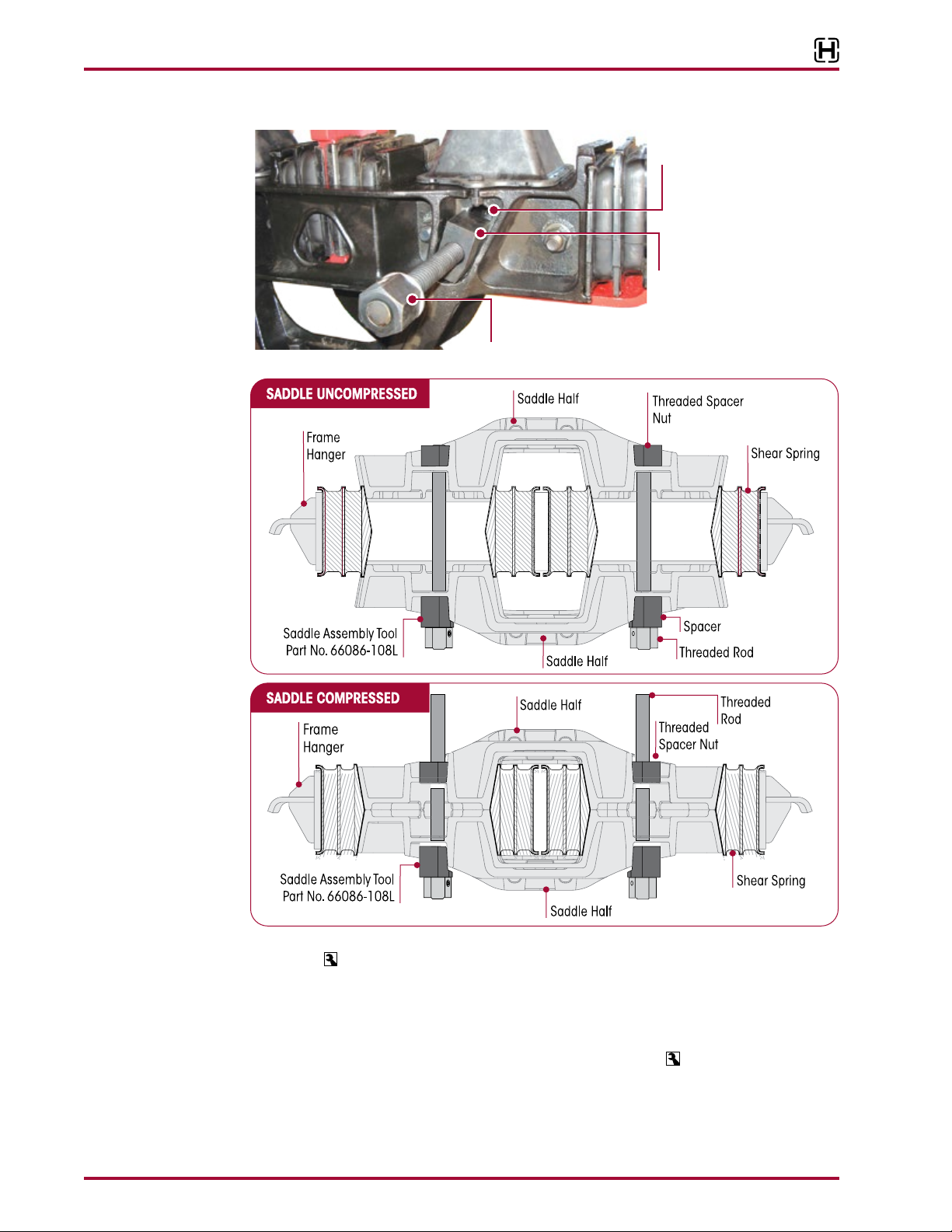
ULTIMAAX® for Fire and Rescue Vehicles
Saddle Assembly
FIGURE 8-10
FIGURE 8-11
Opening
Threaded Rod
Spacer
Saddle Assembly Tool
Hendrickson Part No. 66086-108L
9. Install the new M20 flange saddle fasteners. Tighten in the proper sequence shown in Figure
8-12 to 325 foot pounds plus a 90° rotation, or 560 ± 30 foot pounds torque.
10. Remove temporary tape from the shear springs if used during assembly.
11. Remove each of the saddle assembly tools.
12. Install the progressive load springs (PLS).
13. Install the progressive load spring M10 flange fasteners. Tighten to
30 ± 2 foot pounds torque.
14. Remove the frame supports.
15. Lower the frame of the vehicle while engaging the saddles on the equalizing beam’s center
bushings, see Figure 8-13.
Component Replacement 36 17730-299
Page 37
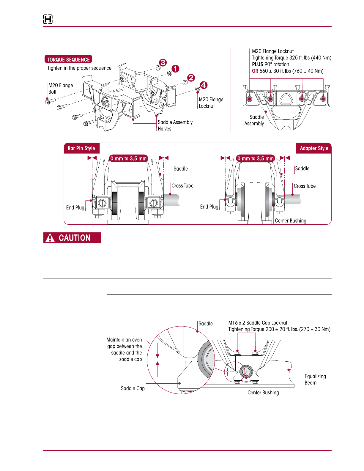
FIGURE 8-12
FIGURE 8-13
ULTIMAAX® for Fire and Rescue Vehicles
A SADDLE ASSEMBLY IS ATTACHED TO THE CENTER BUSHING OF EACH EQUALIZING BEAM WITH TWO
(2) SADDLE CAPS. EACH SADDLE CAP USES TWO (2) BOLTS TO CLAMP THE CENTER BUSHING INNER
METAL TO THE SADDLE. EACH SADDLE CAP MUST BE INSTALLED SO THAT THERE IS AN EVEN GAP
BETWEEN THE SADDLE CAP AND THE BASE OF THE SADDLE LEGS AS SHOWN IN FIGURE 8-14. IF EACH
SADDLE CAP IS NOT INSTALLED EVENLY, THE SADDLE LEGS COULD BECOME DEFORMED, RESULTING
IN BENT BOLTS OR DAMAGED SADDLES.
NOTE Tightening the saddle cap fasteners properly will help prevent wear of mating components, such
as the beam center bushing, saddle, and saddle cap.
16. While tightening the saddle cap fasteners maintain an even gap between the saddle and
saddle cap, see Figure 8-14.
FIGURE 8-14
17730-299 37 Component Replacement
Page 38
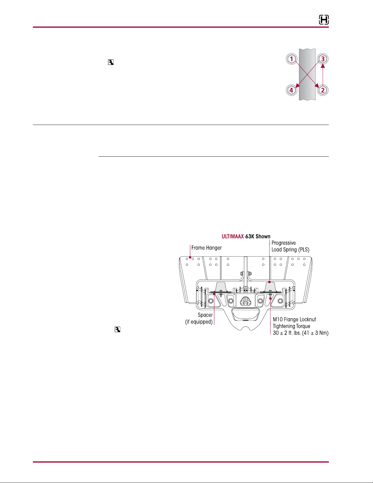
ULTIMAAX® for Fire and Rescue Vehicles
FIGURE 8-15
17. Install the saddle cap fasteners and tighten evenly in several steps to
200± 20foot pounds torque in proper sequence to achieve uniform
bolt tension, see Figure 8-15.
18. Install the tires.
19. Remove supports from the axles and lower the vehicle onto the ground.
20. Remove the wheel chocks.
PROGRESSIVE LOAD SPRING (PLS)
NOTE The Hendrickson ULTIMAAX suspension progressive load springs must be replaced in pairs (left
side pairs or right side pairs or rear position pairs or front position pairs), even if only one PLS
shows unacceptable conditions. Replacement of only one PLS can cause uneven wear, and
higher premature wear for the one replaced.
DISASSEMBLY
1. Chock the front wheels of the vehicle.
2. Raise the vehicle’s frame until the saddle assembly contacts the bottom of the frame hanger
assembly. Support the vehicle’s frame at this height with safety stands.
3. Remove and discard the four M10 flange bolts that attach the progressive load springs to the
saddle assembly, see Figure 8-16.
4. Remove the PLS from the frame hanger assembly.
FIGURE 8-16
ASSEMBLY
1. Install the PLS into the
frame hanger assembly.
2. Install the four M10 flange
bolts that attach the PLS
to the saddle assembly.
The flange bolts must be
installed with the locknuts facing downward as
shown in Figure 8-16.
3. Tighten the PLS fasteners
to
30 ± 2 foot pounds
torque.
4. Remove the frame safety stands and lower the vehicle.
5. Remove the wheel chocks.
EQUALIZING BEAM
DISASSEMBLY
1. Chock the wheels of the steer axle.
2. Raise and support the drive axles with safety stands.
3. Remove the tires.
4. Support the pinion angle of the drive axles to prevent axle movement during service.
5. Remove the saddle cap bolts from both inboard and outboard sides of the equalizing beam.
6. Remove the saddle caps, see Figure 8-17.
Component Replacement 38 17730-299
Page 39
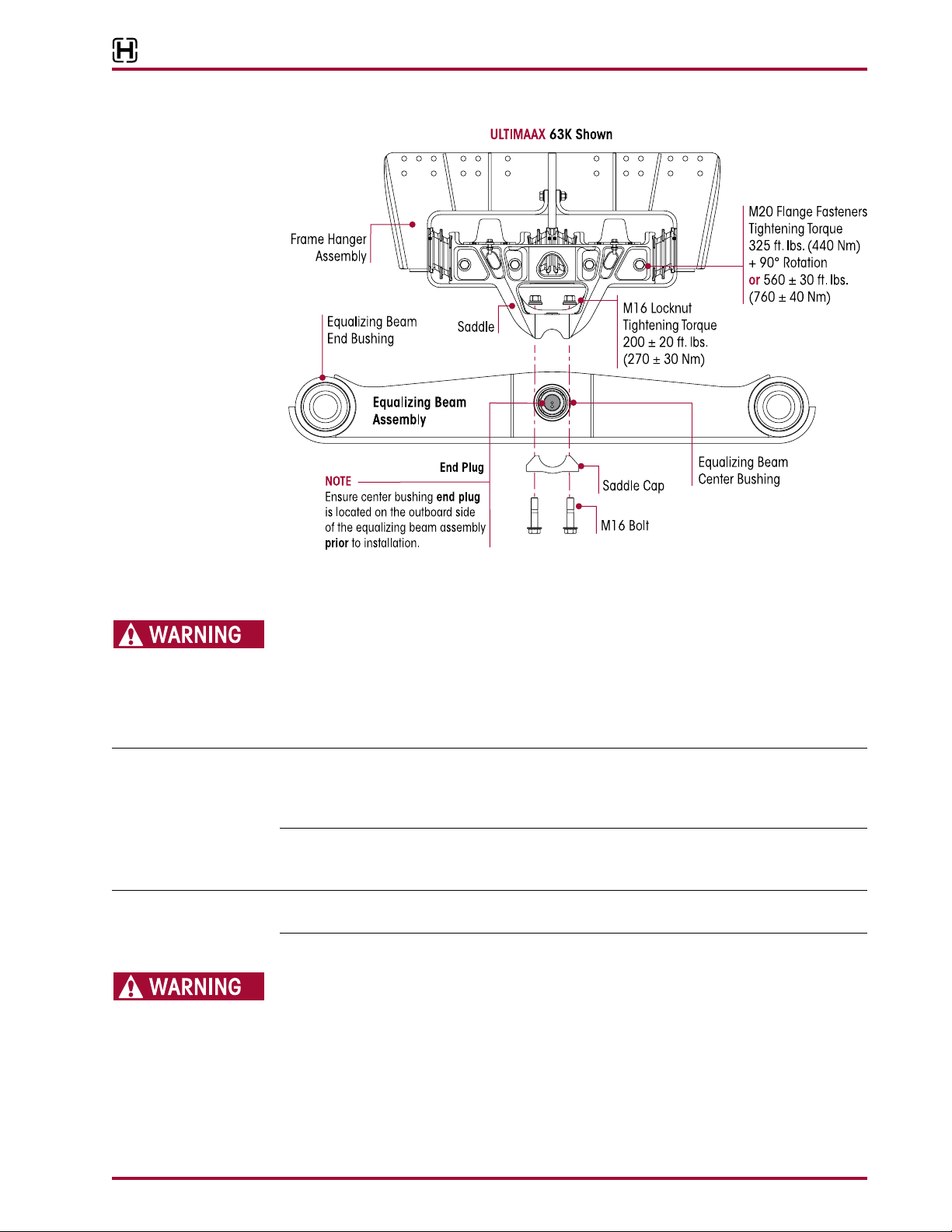
FIGURE 8-17
ULTIMAAX® for Fire and Rescue Vehicles
7. Raise the vehicle’s frame just enough to create a ½" (13 mm) gap between the saddles and
the center bushings. Support the vehicle’s frame at this height with safety stands.
THE WEIGHT OF THE EQUALIZING BEAM ASSEMBLY IS APPROXIMATELY 285 POUNDS (130
KILOGRAMS). PRIOR TO REMOVING THE END BUSHING BOLTS FROM THE EQUALIZING BEAM, SUPPORT
THE END OF THE EQUALIZING BEAM TO PREVENT IT FROM DROPPING. CARE SHOULD BE TAKEN AT
REMOVAL AND INSTALLATION TO PREVENT PERSONAL INJURY OR DAMAGE TO COMPONENTS.
8. Support both equalizing beams under the center bushing with floor jacks.
9. Adapter Style End Bushing – Proceed to Step 11.
NOTE Prior to disassembly of the equalizing beam bar pin fasteners, note the orientation of the bar
pin alignment shims. It is required that the bar pin alignment shims are installed in the same
orientation and location as removed to preserve the existing vehicle alignment. Improper vehicle
alignment can increase tire wear.
10. Bar Pin Style End Bushing – Note the orientation and location of the bar pin shims.
11. Remove and discard end bushing fasteners.
SERVICE HINT The center bushing will allow the cross tube and the equalizing beam to angle downward once
the equalizing beam end fasteners are removed.
12. Slowly lower the floor jacks and remove the equalizing beams from the axle brackets.
PRIOR TO REMOVING BOTH EQUALIZING BEAMS, SUPPORT THE PINION OF EACH DRIVE AXLE. FAILURE
TO DO SO CAN RESULT IN PERSONAL INJURY OR ALLOW THE AXLES TO SHIFT MAKING REASSEMBLY
MORE DIFFICULT.
13. Slide the equalizing beams off the cross tube and out from under the vehicle.
14. Remove the floor jacks from under the equalizing beams.
ASSEMBLY
1. Position the equalizing beams under the axles with floor jacks.
17730-299 39 Component Replacement
Page 40
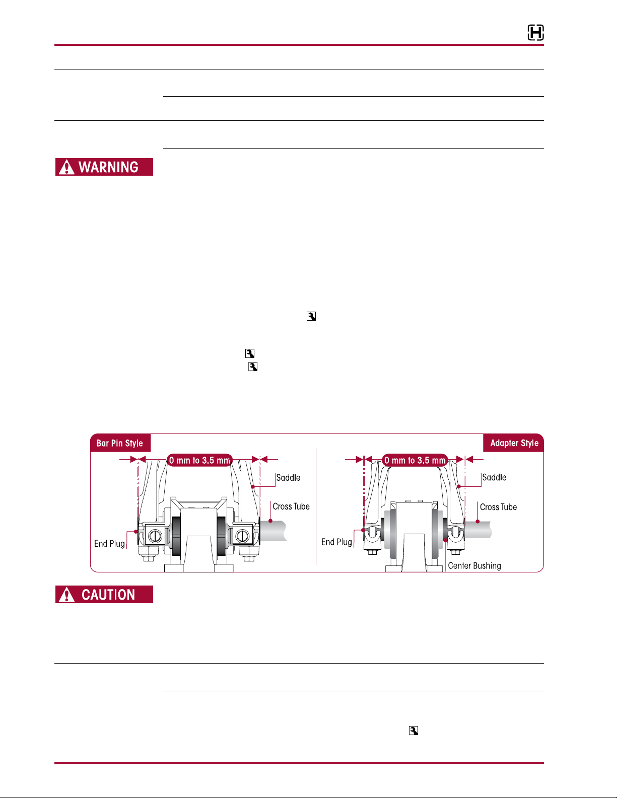
ULTIMAAX® for Fire and Rescue Vehicles
SERVICE HINT Ensure the equalizing beam’s center bushing end plug is located on the outboard side of the
equalizing beam, see Figure 8-17.
2. Push down and install the cross tube into the center bushings of both equalizing beams.
SERVICE HINT Increasing or decreasing the pinion angle may help align the axle bracket and the equalizing
beam end bushings.
THE WEIGHT OF THE EQUALIZING BEAM ASSEMBLY IS APPROXIMATELY 285 POUNDS (130
KILOGRAMS). PRIOR TO REMOVING THE END BUSHING BOLTS FROM THE EQUALIZING BEAM, SUPPORT
THE END OF THE EQUALIZING BEAM TO PREVENT IT FROM DROPPING. CARE SHOULD BE TAKEN AT
REMOVAL AND INSTALLATION TO PREVENT PERSONAL INJURY OR DAMAGE TO COMPONENTS.
3. Using the floor jacks, slowly raise both equalizing beams and cross tube as an assembly into
the axle brackets. Ensure each equalizing beam end bushing correctly engages its respective
axle bracket.
4. Adapter Style End Bushing – Proceed to Step 6.
5. Bar Pin Style End Bushing – Install bar pin shims in the same orientation and location as
noted prior to disassembly.
6. Install new end bushing fasteners into both beams. Tighten the end bushing fasteners to:
FIGURE 8-18
■
Adapter Style End Bushing –
torque.
■
Bar Pin Style End Bushing at the –
●
Locknuts 525 ± 75 foot pounds (712 ± 102 Nm) or
●
Bolt head 575 ± 75 foot pounds (780 ± 102 Nm) torque
7. Remove the frame supports.
8. Lower the frame of the vehicle while engaging and centering the saddles on the equalizing
beam’s center bushings, see Figure 8-18.
125 foot pounds + 90° rotation or 700 ± 50 foot pounds
A SADDLE ASSEMBLY IS ATTACHED TO THE CENTER BUSHING OF EACH EQUALIZING BEAM WITH TWO
(2) SADDLE CAPS. EACH SADDLE CAP USES TWO (2) BOLTS TO CLAMP THE CENTER BUSHING INNER
METAL TO THE SADDLE. EACH SADDLE CAP MUST BE INSTALLED SO THAT THERE IS AN EVEN GAP
BETWEEN THE SADDLE CAP AND THE BASE OF THE SADDLE LEGS AS SHOWN IN FIGURE 8-19. IF EACH
SADDLE CAP IS NOT INSTALLED EVENLY, THE SADDLE LEGS COULD BECOME DEFORMED, RESULTING
IN BENT BOLTS OR DAMAGED SADDLES.
NOTE Tightening the saddle cap fasteners properly will help prevent wear of mating components, such
as the beam center bushing, saddle, and saddle cap.
9. While tightening the saddle cap fasteners maintain an even gap between the saddle and
saddle cap, see Figure8-19.
10. Tighten the saddle cap fasteners evenly in several steps to
200±20 foot pounds torque in
proper sequence to achieve uniform bolt tension, see Figure 8-20.
Component Replacement 40 17730-299
Page 41
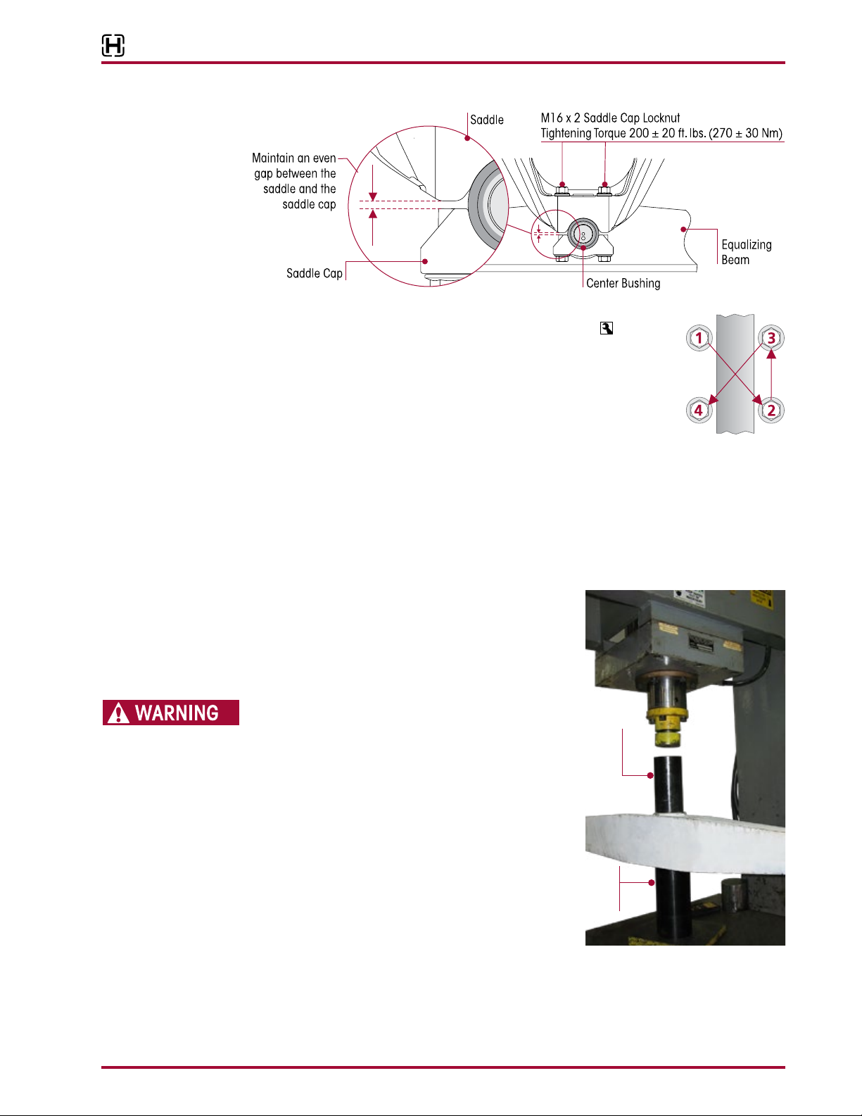
ULTIMAAX® for Fire and Rescue Vehicles
FIGURE 8-19
FIGURE 8-20
11. Tighten the saddle cap fasteners evenly in several steps to 200±20
foot pounds torque in proper sequence to achieve uniform bolt tension,
see Figure 8-20.
12. Install the tires.
13. Remove the support from the axles and lower the vehicle onto the ground.
14. Remove the wheel chocks.
EQUALIZING BEAM CENTER BUSHING
You will need:
■
Vertical shop press with a capacity of at least 100 Tons.
■
Center bushing tools – Receiving Tool No. 66086-112, Installation Tool No. 66086-107 and
Removal Tool No. 66086-110, see Special Tools Section of this publication.
FIGURE 8-21
DISASSEMBLY
1. Remove the equalizing beam assembly
from the vehicle. Follow the equalizing
beam disassembly procedure in this
section.
DO NOT USE A CUTTING TORCH TO REMOVE
ANY FASTENERS OR BUSHINGS. THE USE
OF HEAT ON SUSPENSION COMPONENTS
WILL ADVERSELY AFFECT THE STRENGTH OF
THESE PARTS. A COMPONENT DAMAGED IN
THIS MANNER CAN RESULT IN THE ADVERSE
VEHICLE HANDLING AND POSSIBLE PERSONAL
INJURY OR PROPERTY DAMAGE.
2. Place the equalizing beam assembly in
a shop press with the center hub firmly
supported on the receiving tool or on the
press, see Figure 8-21.
3. Install the center bushing removal tool,
ensure it is centered on the center
bushing.
4. Push directly on center bushing removal tool until the center bushing is pressed out of the
equalizing beam bore, see Figure 8-21.
5. Inspect the beam bore.
Center Bushing
Removal Tool
Part No. 66086-110
Equalizing Beam Assembly
Center Bushing
Receiving Tool
Part No. 66086-112
17730-299 41 Component Replacement
Page 42
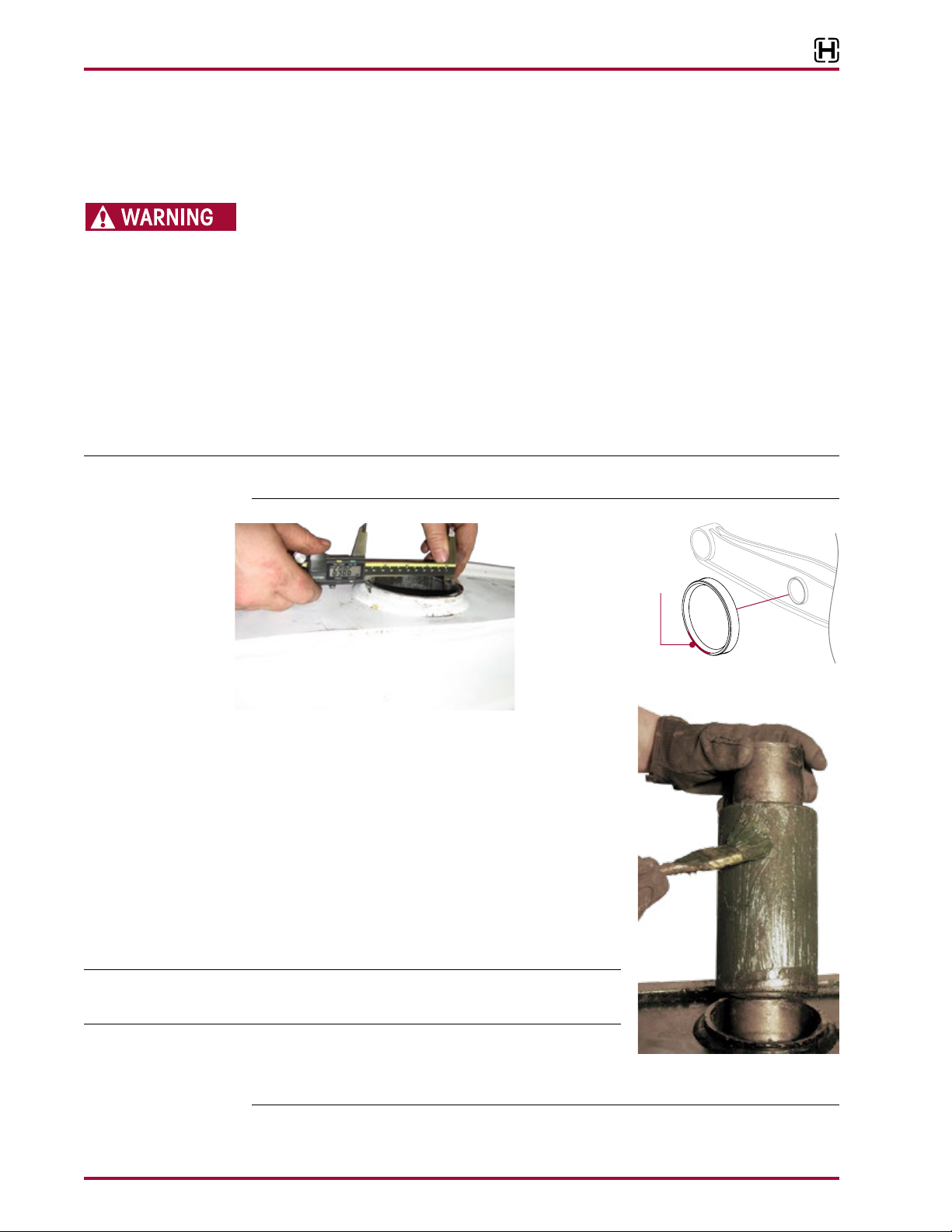
ULTIMAAX® for Fire and Rescue Vehicles
INSPECTION
After removing the center bushing, thoroughly inspect the beam bore. If damaged, replace
with a new equalizing beam. DO NOT attempt to re-bush or use an equalizing beam that has
been damaged.
FAILURE TO REPLACE AN EQUALIZING BEAM THAT HAS BEEN DAMAGED FROM BUSHING REMOVAL
CAN RESULT IN THE FAILURE OF THAT BEAM, LEADING TO ADVERSE VEHICLE HANDLING AND POSSIBLE
PERSONAL INJURY OR PROPERTY DAMAGE.
When installing new center bushings the following steps will minimize the chance of damaging
a new bushing:
1. Clean the bore of the equalizing beam with emery cloth or ball hone, removing any nicks or
metal buildup from bushing removal.
2. Measure the inside diameter of the equalizing beam center bore. The specification for the
inside diameter of the equalizing beam center bore on a new ULTIMAAX equalizing beam is
3.886" ± 0.003" (98.7 mm ± 0.1 mm), calculate the mean of any two measurements 90°
apart in the same plane, see Figure 8-22. If the mean is NOT within the specified range, replacement of the equalizing beam is required.
NOTE Always use the bushing outer metal for pressing operations. Pressing on the bushings inner metal
may damage the bushing and require bushing replacement.
FIGURE 8-22 FIGURE 8-23
Lead in Chamfer Edge
in Equalizing Beam
Center Bushing Bore
Inside diameter of the equalizing beam center
bore on a new ULTIMAAX equalizing beam is
3.886" ± 0.003" (98.7 mm ± 0.1 mm)
FIGURE 8-24
ASSEMBLY
1. The equalizing beam bore may have a more substantial
lead in chamfer at one end of the bore than the other,
see Figure 8-23. Take advantage of the larger chamfer by
pressing in the new bushing from this end.
2. Place the equalizing beam in a shop press on the receiving tool or press. Support the beam squarely at the center
bore area to avoid distortion of the beam bore or bending
of the beam.
3. Lubricate the equalizing beam bore and the equalizing beam center bushing outer metal sleeve with an
NLGI#2–EP (Extreme Pressure) grease, see Figure 8-24.
NOTE The ULTIMAAX center bushing has voids that must be
positioned horizontally front and back, see Figure 8-25.
NOTE The center bushing must be square with the equalizing beam
hub before pressing the center bushing into the beam. Center
bushings pressed in at an angle will damage the center bushing and the equalizing beam, see
Figure 8-26.
Component Replacement 42 17730-299
Page 43
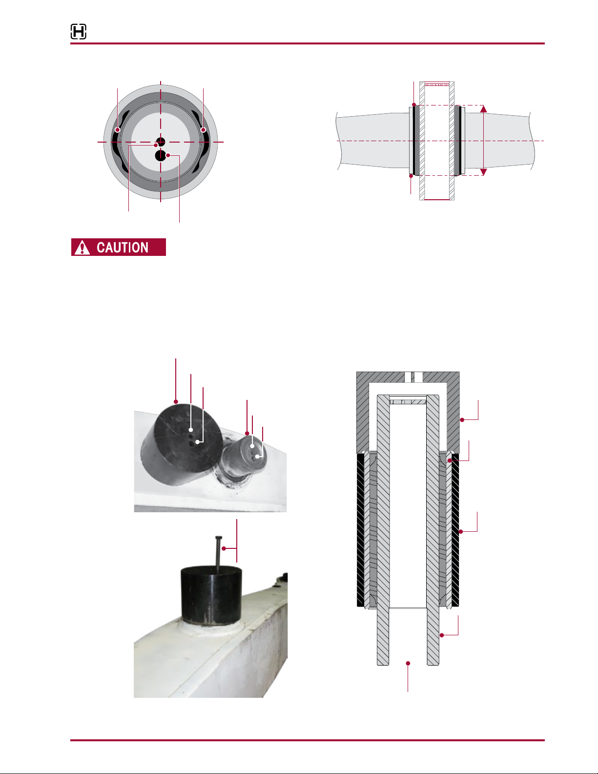
ULTIMAAX® for Fire and Rescue Vehicles
and the second locating
FIGURE 8-25 FIGURE 8-26
Void
Void
Center Bushing
Outer Metal
Center
Hole
C
Equalizing Beam
L
Second Locating
Bottom Hole
Horizontal Centerline
Verify the voids are
perpendicular to the
horizontal centerline
hole is on the bottom
End Hub
CLC
L
Press the center bushing
until the center bushing
outer metal sleeve is
centered in the end hub.
CLC
L
ALWAYS USE THE CENTER BUSHING OUTER METAL FOR PRESSING OPERATIONS. PRESSING ON THE
CENTER BUSHING’S INNER METAL WILL CAUSE DAMAGE TO THE CENTER BUSHING AND REQUIRE
CENTER BUSHING REPLACEMENT.
4. Install the center bushing installation tool, Part no. 66086-107, making sure the voids are positioned horizontally front and back and press in the new center bushing until the outer metal
sleeve is centered in the equalizing beam bore, see Figures 8-25 through 8-28.
5. Install the equalizing beam assembly to the vehicle. Follow the equalizing beam installation
procedure in this section.
FIGURE 8-27 FIGURE 8-28
Center Bushing Installation Tool
Center Hole
Bottom Hole
Center Bushing
Center Hole
Bottom Hole
Center Bushing
Installation Tool
Center Bushing
Outer Metal
Verify both the center
hole and second
locator bottom hole
align properly
Equalizing
Beam
Center Bushing
Hollow End
17730-299 43 Component Replacement
Equalizing Beam
Center Hub
Center Bushing
Page 44
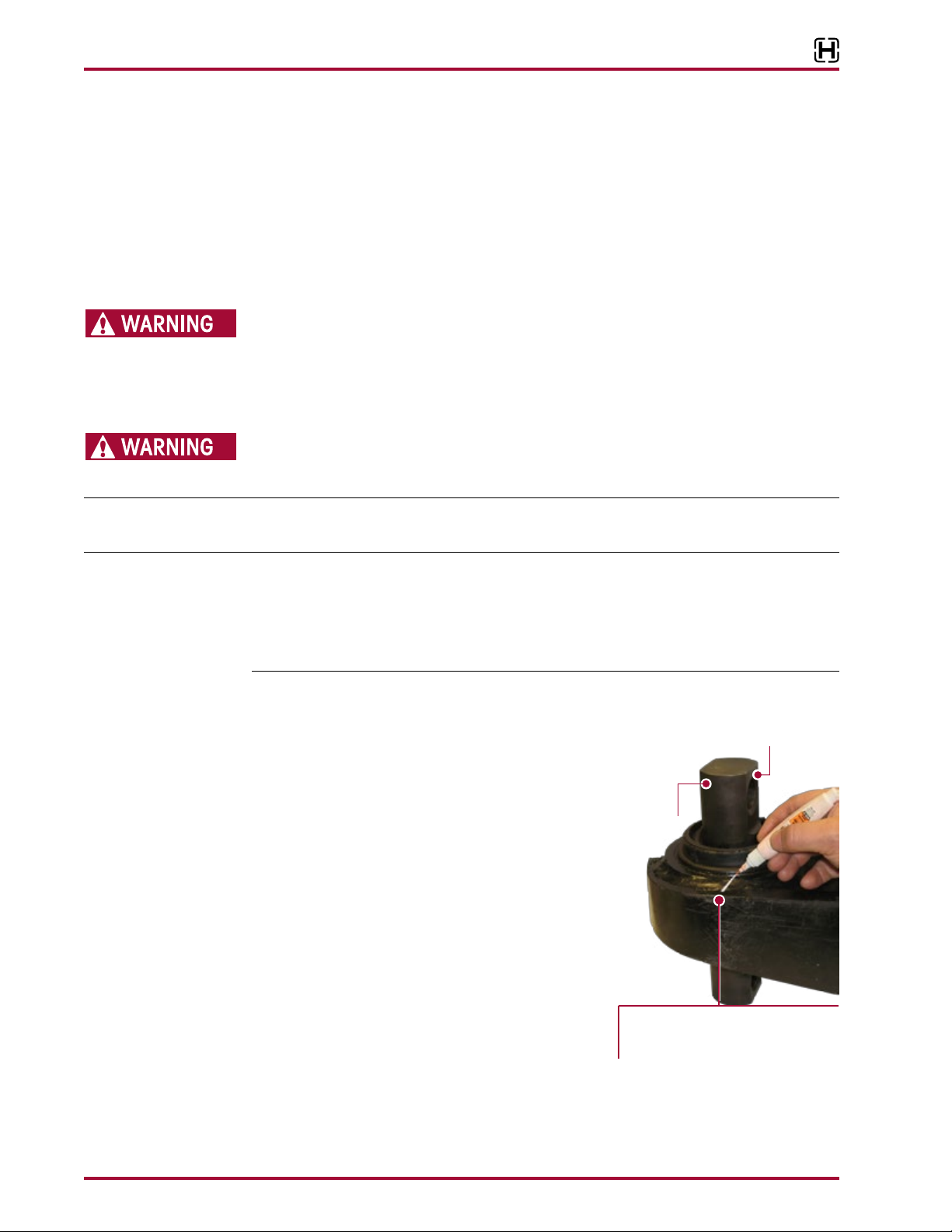
ULTIMAAX® for Fire and Rescue Vehicles
beam end hub
Bar Pin
BAR PIN STYLE END BUSHINGS
You will need:
■
A shop press with a capacity of at least 100 tons
■
End bushing service kit, refer to the Parts List Section of this publication.
■
End bushing tools – Receiving Tool No. 66086-111, Installation Tool No. 66086-106 and
Removal Tool No. 66086-109, see Special Tools Section of this publication.
DISASSEMBLY
WHEN REMOVING AND INSTALLING BUSHINGS IN THE EQUALIZING BEAMS, FOLLOW THE PROCEDURES
OUTLINED IN THIS PUBLICATION. DO NOT USE A CUTTING TORCH TO REMOVE THE BUSHING OUTER
METALS PRESSED IN THE BEAM BORES OR FASTENERS. WELDING, TORCHING OR ATTACHING MATERIAL
TO THE EQUALIZING BEAM MUST NEVER BE PERFORMED. THE USE OF HEAT CAN ADVERSELY AFFECT
THE STRENGTH OF THE EQUALIZING BEAMS AND CAN CAUSE DAMAGE TO THE EQUALIZING BEAM
ASSEMBLY, ADVERSE VEHICLE HANDLING AND POSSIBLE PERSONAL INJURY OR PROPERTY DAMAGE.
DISCARD USED FASTENERS. ALWAYS USE NEW FASTENERS TO COMPLETE A REPAIR. FAILURE TO DO SO
COULD RESULT IN FAILURE OF THE PART OR MATING PARTS, ADVERSE VEHICLE HANDLING, PERSONAL
INJURY, OR PROPERTY DAMAGE.
NOTE Hendrickson recommends the use of Grade 8 bolts, hardened washers, and Class C locknuts.
Hardened washers are not necessary when flange head fasteners are used.
NOTE Whenever an equalizing beam is removed for repair or inspection of the equalizing beam end
connection reveals movement, measure the distance between the axle bracket legs for correct
width. Refer to Axle Bracket in Preventive Maintenance Section of this publication for measurement
location and dimensions. An axle bracket outside of the measurement range must be repaired or
replaced. Consult the vehicle manufacturer for inspection, component repair and replacement
instructions.
1. Remove equalizing beam assembly from vehicle as detailed in the equalizing beam disassembly instructions in this section.
FIGURE 8-29
2. Place the equalizing beam in the shop press with the
beam end hub squarely supported on the receiving
tool (Part No. 66086-111) or press bed.
3. Prior to removal, mark the orientation of the bar pin
Inner
Metal
Flat
flats on the equalizing beam with a paint stick, see
Figure 8-29.
4. Support the beam end hub with it centered on the
receiving tool. Be sure the equalizing beam is squarely
supported on the press bed for safe ty.
5. Press on the end bushing inner metal, see Figure8-29,
of the end bushing until the inner metal is flush with
the top of the equalizing beam end hub. This will move
the bushing rubber away from the outer metal of the
bushing so the removal tool (Part No. 66086-109)
can be installed.
Mark the location of the bar pin ats
with a paint stick on the equalizing
6. Center the bushing removal tool directly on the bushing’s outer metal and press the bushing out of the equalizing beam end hub.
Component Replacement 44 17730-299
Page 45
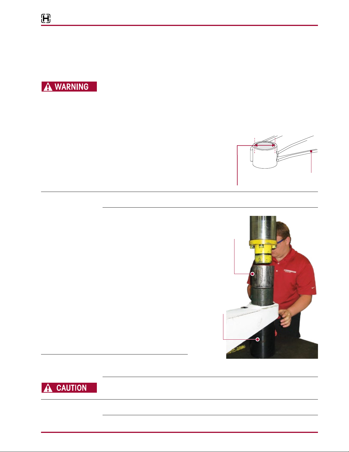
ULTIMAAX® for Fire and Rescue Vehicles
(117.28 mm / 117.48 mm)
Receiving Tool
INSPECTION
After removing the bar pin end bushings, thoroughly inspect the beam bores. If the equalizing
beam is damaged from end bushing removal, replacement of the equalizing beam is required,
replace with a new equalizing beam. DO NOT attempt re-bush or use an equalizing beam that
has been damaged.
FAILURE TO REPLACE AN EQUALIZING BEAM THAT HAS BEEN DAMAGED FROM BUSHING REMOVAL
CAN RESULT IN THE FAILURE OF THAT BEAM, ADVERSE VEHICLE HANDLING AND POSSIBLE PERSONAL
INJURY OR PROPERTY DAMAGE.
1. Clean the bores of the equalizing beams with emery cloth or ball hone, removing any nicks or
metal buildup from bushing removal.
FIGURE 8-30
2. Measure the equalizing beam end hub bore inner
diameter. The Hendrickson specification for the equalizing beam end hub bore diameter is 4.621" ± 0.004"
(117.38 mm ± 0.10 mm), and is taken as the mean
of any two readings 90° apart in the same plane, see
Figure 8-30. If it is NOT within the specified range,
replacement is required.
ASSEMBLY
Equalizing Beam
End Hub Bore Diameter
Equalizing
Beam
4.617" / 4.625"
NOTE Always use the bushing outer metal for pressing operations. Pressing on the bushings inner metal
may damage the bushing and require bushing replacement.
FIGURE 8-31
1. The equalizing beam bore may
have a more substantial lead in
chamfer at one end of the bore
than the other. Take advantage of
the larger chamfer by pressing in
the new end bushing from this end.
End Bushing
Installation Tool
Part No.
66086-106
2. Lubricate the equalizing beam
end hub inside bore and the bar
pin end bushing outer sleeve with
a NLGI #2 – EP (Extreme Pressure)
grease.
3. Place the equalizing beam in
a shop press with the end hub,
squarely supported on the receiving tool, see Figure8-31.
4. Position and align the end bush-
End Bushing
Part No.
66086-111
Equalizing
Beam
ing to the mark made before
removal as shown in Figure8-29.
NOTE The end bushing must be square with
the equalizing beam end hub before pressing the end bushing into the beam. End bushings
pressed in at an angle will damage the end bushing and the equalizing beam.
CARE MUST BE TAKEN DURING THE INSTALLATION OF THE BUSHING. DO NOT PUSH ON THE INNER
NOTE Always use the bushing outer metal for pressing operations. Pressing on the bushings inner metal
17730-299 45 Component Replacement
METAL OF THE BUSHING, DOING SO WILL CAUSE DAMAGE TO THE BUSHING AND VOID WARRANTY.
may damage the bushing and require bushing replacement.
5. Place the end bushing installation tool on the end hub.
Page 46
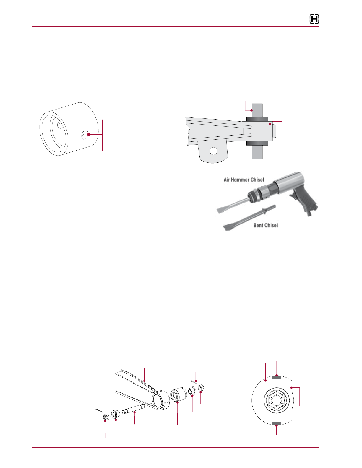
ULTIMAAX® for Fire and Rescue Vehicles
equalizing beam
Beam End
Flat Side
Chisel Recess
Chisel
63K ShownULTIMAAX
6. The through hole in the tool can help align the bar pin flats due to lack of visibility. Place a bolt
with enough length to go through the tool and the bar pin hole, see Figure 8-32.
7. With the tools align, press in the end bushing, see Figure 8-31.
8. The end bushing must be centered within the hub of the equalizing beam, see Figure 8-33.
9. Install the equalizing beam assembly into vehicle as detailed in equalizing beam assembly
in this section.
FIGURE 8-32 FIGURE 8-33
66086-106
End Bushing Installation Tool
Bar Pin
Equalizing Beam
End Hub
Through hole can be used to
help align the bar pin ats due
to lack of visibility.
Place a bolt through the tool
and bar pin hole.
FIGURE 8-34
ADAPTER STYLE END BUSHINGS
You will need:
■
A shop press with a capacity of at least 100
tons
■
Air hammer / chisel / Bent chisel, see
Figure8-34
■
Hendrickson Tool No. 66086-101 (OTC Part
No. 1763), see Special Tools Section of this publication
DISASSEMBLY
NOTE It is recommended that a penetrating oil be applied to all beam end connections.
1. Remove the cotter pins, slotted nuts and end bushing adapter tube, see Figure 8-35.
2. The beam end adapters have two chisel recesses located in their flanges as shown in
Figure8-36.
3. Locate the recess for the chisel, rotate the adapter if necessary. Place the air hammer/chisel
in the recess.
4. If the adapter does not turn, use a hammer to rap the outside of the axle bracket legs around
the adapter area and repeat with the air hammer chisel.
5. Support the end of the equalizing beam as it may drop when the other adapter is removed.
6. Remove remaining adapters.
FIGURE 8-35 FIGURE 8-36
Outer metal is
centered in the
end hub
Equalizing
Beam
Beam End Shaft
Component Replacement 46 17730-299
Beam End Adapter
7
1/" Slotted Nut
8
Adapter Style
End Bushing
Cotter Pin
7
8
1/" Slotted Nut
Beam End Adapter
Adapter
Recess
Adapter
Vertical
Page 47
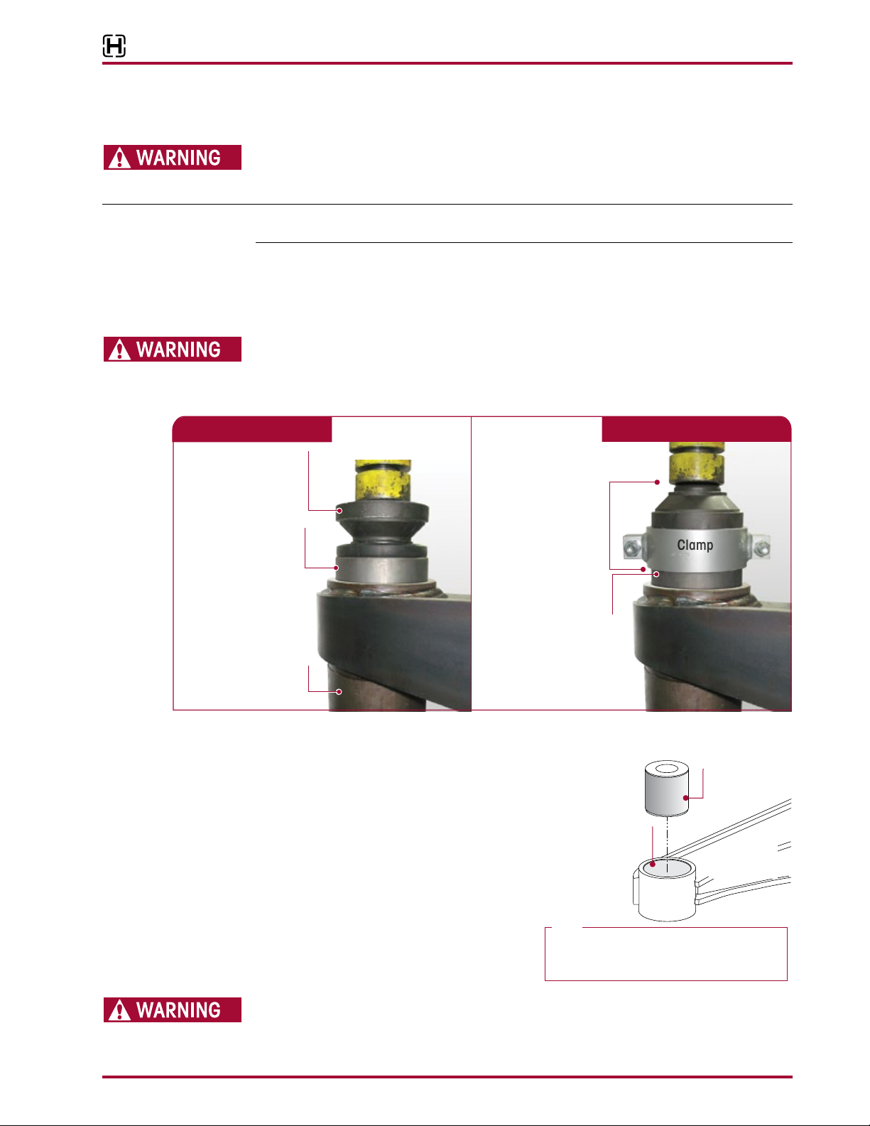
ULTIMAAX® for Fire and Rescue Vehicles
Clamp
7. When the adapter has enough clearance between the axle bracket and the adapter flange,
use a bent chisel as shown in Figure 8-34 to wedge and force the adapter out.
THE ADAPTER REMOVAL PROCESS CAN CAUSE DAMAGE. REUSE OF DAMAGED OR WORN ADAPTERS
COULD RESULT IN A COMPONENT FAILURE LEADING TO ADVERSE VEHICLE HANDLING AND POSSIBLE
PERSONAL INJURY.
NOTE Due to the process necessary to remove the adapters, the adapter can be subjected to damage.
DO NOT reuse worn or damaged adapters. Replace as necessary.
8. Remove the equalizing beam assembly from vehicle as detailed in the Equalizing Beam
Disassembly instructions in this section.
9. Position the equalizing beam in the shop press and align the End Bushing Removal /
Replacement Adapter with the tapered end facing the bushing to be removed, see Figure8-37.
CHECK TO INSURE PROPER ALIGNMENT OF TOOLING ADAPTERS WITH EQUALIZING BEAM
COMPONENTS BEFORE APPLYING FULL HYDRAULIC PRESSURE WITH A SHOP PRESS.
10. Apply hydraulic force and push out the old bushing.
FIGURE 8-37 FIGURE 8-38
END BUSHING REMOVAL
End Bushing
Removal / Replacement
Adapter Tool
Part No. 66086-101
End
Bushing
Receiver
ASSEMBLY
FIGURE 8-39
1. Clean the end bushing bore with a cylinder
ball hone or emery paper. Clean any debris.
2. Lubricate the equalizing beam bore and
the equalizing beam center bushing outer
metal sleeve with an NLGI#2 – EP (Extreme
Pressure) grease, see Figure 8-39.
3. Position the end bushing removal / replacement adapter, with the tapered end facing
away from the new bushing, onto the clamp,
see Figure 8-38.
4. Wrench tighten the clamp onto the bushing
and the adapter as shown in Figure8-38.
Equalizing Beam
End Bushing
Removal / Replacement
Adapter Tool
Part No. 66086-101
End
Bushing
Adapter Style
End Bushing
Equalizing Beam
NOTE
Lubricate the inside diameter of andEND HUB
the end bushing with #2-OUTER METAL NLGI EP
(Extreme Pressure) lithium base grease
END BUSHING INSTALLATION
Clamp
Equalizing Beam
Outer Metal
End Hub
Equalizing
Beam
ENSURE PROPER ALIGNMENT OF TOOLING ADAPTERS WITH EQUALIZING BEAM COMPONENTS BEFORE
APPLYING FULL HYDRAULIC PRESSURE WITH A SHOP PRESS.
17730-299 47 Component Replacement
Page 48
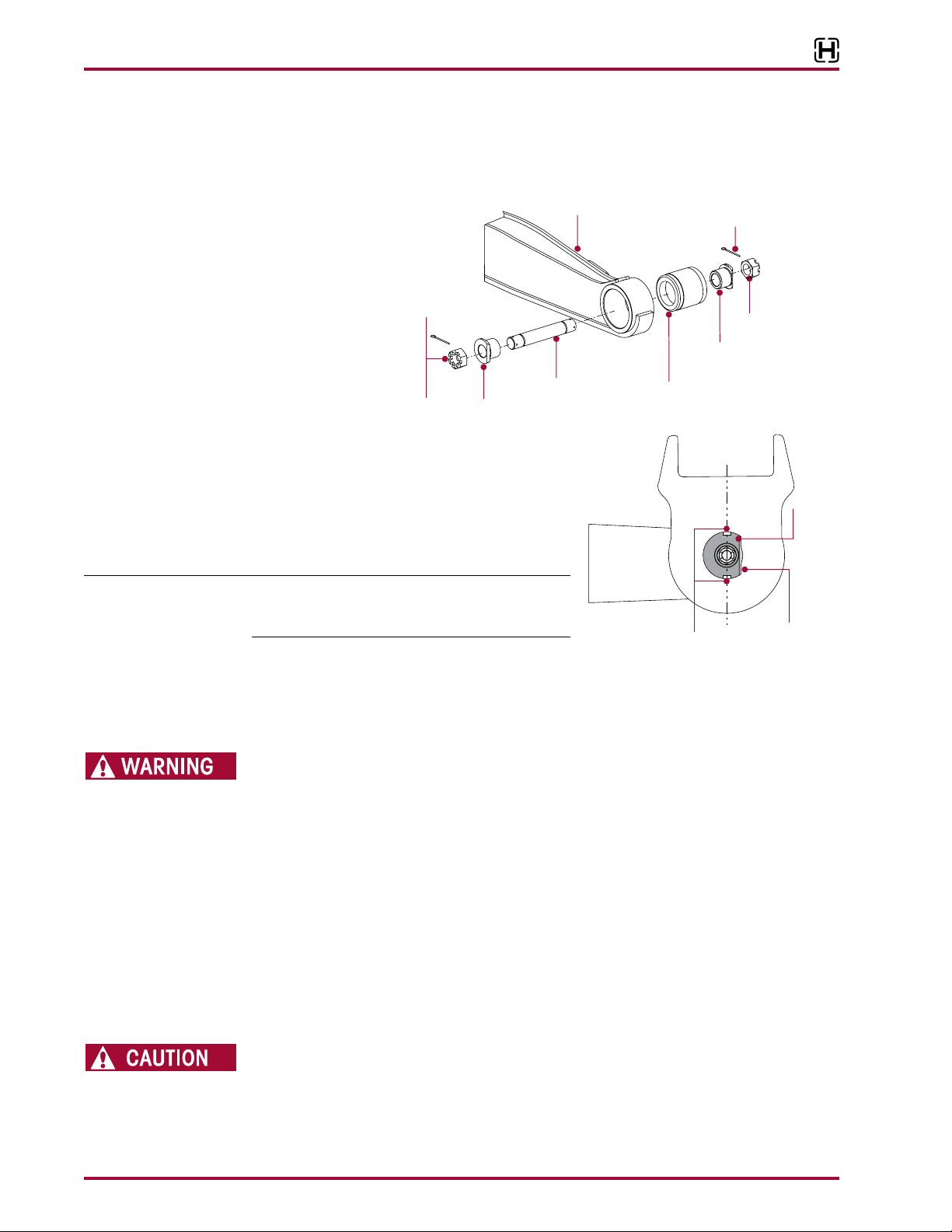
ULTIMAAX® for Fire and Rescue Vehicles
ed Nut
700 ± 50 ft.
Flat Side
5. Apply hydraulic force and press the new bushing into place. The bushing will be completely
seated when the clamp makes contact with the beam face.
6. Install one adapter through the axle bracket leg at the wheel side, into the beam end bushing,
see Figure 8-40.
FIGURE 8-40
63K ShownULTIMAAX
7
8
1/" Slotted Nut
Tightening Torque
125 ft. lbs. (170 Nm)
+ 90° rotation or
lbs.(949 ± 68 Nm)
FIGURE 8-41
7. Install the other adapter through the axle bracket
leg at the axle side, taking advantage of the cutoff flange on the adapter to clear the axle.
8. Insert adapter connections, see Figure 8-41.
9. Rotate the adapters so the adapter cut off flats
are vertical as shown in Figure 8-41.
NOTE Axles must be in operational position before fasten-
ers are tightened to prevent pre-loading of the rubber
bushing.
Beam End Adapter
Equalizing Beam
Beam End Shaft
Equalizing
Beam
Chisel Reliefs
Beam End Adapter
Adapter Style
End Bushing
Axle Bracket
Cotter Pin
7
8
1/" Slott
Adapter
Adapter
Vertical
10. Assemble one slotted nut to the shaft and install the cotter pin. Place a suitable wrench on the
nut and ensure the wrench is locked in place (braced) to prevent movement. Tighten using
one of the following torque procedure.
TORQUE PROCEDURE
IF THE RECOMMENDED TORQUE VALUE IS NOT PROPERLY MAINTAINED, THE METAL SURFACES OF THE
AXLE BRACKET LEGS, HOLES, ADAPTERS AND RUBBER BUSHING INNER METALS CAN EXPERIENCE
EXCESSIVE WEAR AND/OR FAILURE. THIS CAN CAUSE SEPARATION OF COMPONENTS AND ADVERSE
VEHICLE HANDLING, PROPERTY DAMAGE OR PERSONAL INJURY.
A simple torque wrench will not be sufficient to obtain the proper torque requirement. The proper
torque requirement can be obtained with the use of a torque multiplier. If one is not available the
use of a slug wrench is recommended.
METHOD A: TORQUE MULTIPLIER
You will need:
■
Torque Multiplier
a. Assemble the opposite nut and use a torque wrench with multiplier.
b. Tighten the nut to torque multiplier value 700 ± 50 Foot Pounds torque, see Table 1.
DO NOT BACK OFF NUT TO INSTALL COTTER PIN, DOING SO MAY REDUCE THE TIGHTENING TORQUE
BELOW THE REQUIRED SPECIFICATION.
c. Install cotter pin. The nut may be advanced to the next nut slot. DO NOT back off nut.
Component Replacement 48 17730-299
Page 49
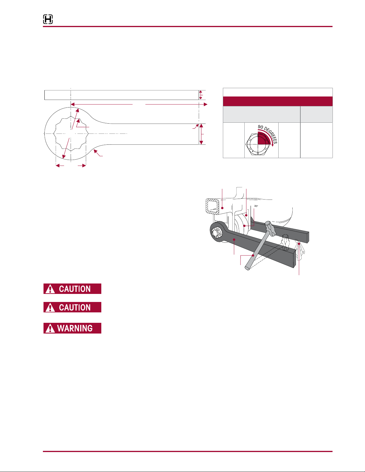
FIGURE 8-42
Min. Hex 12 Point
¾"
2"
2/"
13
16
2½"
1
16
/" R
5"
14¾"
1
8
/" R
ed in Place
ULTIMAAX® for Fire and Rescue Vehicles
METHOD B: SLUG WRENCH
You will need:
■
Two slug wrenches (see Figure 8-42)
■
4 pound hammer
TABLE 1
125 Foot
Pounds
FIGURE 8-43
a. Assemble the opposite nut and
using a torque wrench, tighten
the nut to the initial torque
value shown in Table 1.
b. Remove torque wrench and
replace with the Slug Wrench.
Using a four pound hammer,
tighten the assembly by hitting the slug wrench near the
handle as shown in Figure 8-43
until the nut has been turned to
the degrees specified in Table 1.
Axle
Slug Wrench
4 lb.Hammer
TORQUE SPECIFICATIONS
SLUG WRENCH METHOD
1
90º turn
on castle
Axle Bracket Legs
Equalizing Beam
End Hub
TORQUE
MULTIPLIER
⁄4 or
700 ± 50 Foot
Pounds
nut
Lock
(Braced)
DO NOT BACK OFF NUT TO INSTALL COTTER PIN, DOING SO MAY REDUCE THE TIGHTENING TORQUE
BELOW THE REQUIRED SPECIFICATION.
REPEATED HAMMERING BEYOND THE DEGREE SPECIFIED CAN CAUSE COMPONENT DAMAGE.
c. Install cotter pin. The nut may be advanced to the next nut slot, DO NOT back off nut.
INSUFFICIENT TIGHTENING TORQUES CAN CAUSE PREMATURE WEAR AND DAMAGE TO THE AXLE
BRACKET LEGS, HOLES AND/OR BEAM END CONNECTION COMPONENTS, THIS CAN FURTHER CAUSE
FAILURE AND SEPARATION OF COMPONENTS, AND RESULT IN ADVERSE VEHICLE HANDLING, SEVERE
PERSONAL INJURY OR DEATH. MAINTAIN PROPER TIGHTENING TORQUES AT ALL TIMES.
17730-299 49 Component Replacement
Page 50
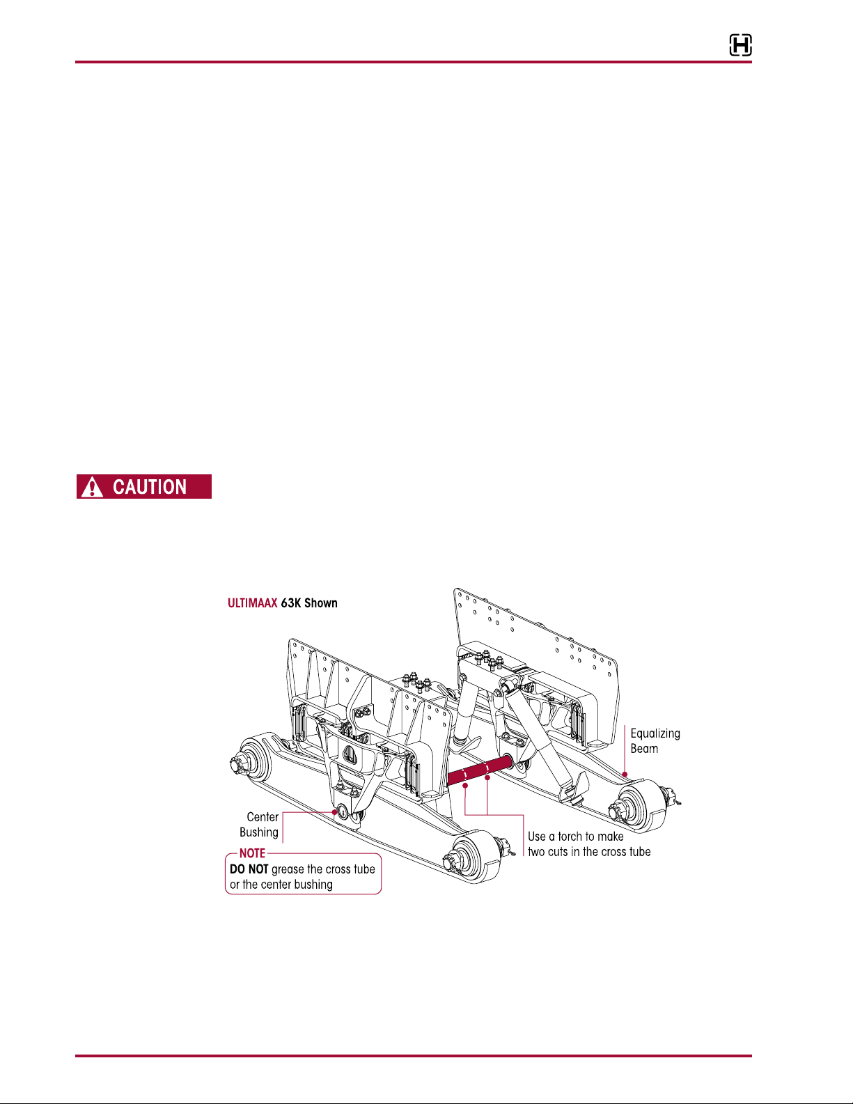
ULTIMAAX® for Fire and Rescue Vehicles
CROSS TUBE
A cross tube seldom requires replacement, usually only when it has been bent, possibly due to
hitting an object. A bent cross tube may cause misalignment of the axles, and must be replaced
immediately to eliminate abnormal tire wear.
Method A Equalizing Beam Removal Method - Follow the steps in the Equalizing Beam
Component Replacement procedure in this section.
Within the procedure, after removal of the equalizing beams when the equalizing beams are
separated, remove and replace cross tube.
Method B Center Bushing End Plug Removal
You will need:
■
Cross Tube Service Kit 60961-759 (see Parts Lists Section)
■
Cutting Torch
■
Welding Equipment
■
Hole Saw
DISASSEMBLY
1. Use a work bay with a level on a flat surface.
2. Chock the front steer axle wheels.
FOLLOW THE SAFETY GUIDELINES FOR OPERATING THE TORCH. USE CAUTION AS PARTS MAY BE HOT.
3. Using a cutting torch, make two cuts in the cross tube, see Figure 8-44.
4. Remove the cut section of the cross tube, slide each remaining section of the cross tube and
discard.
5. Use a 2" hole saw and remove only one center bushing end plug from the suspension.
FIGURE 8-44
ASSEMBLY
1. Clean the open end of the center bushing bore to approximately 1" depth of weld and debris.
2. From the open center bushing slide the new cross tube into both center bushings.
3. It may be necessary to use a floor jack under one or both equalizing beams to align the cross
tube.
Component Replacement 50 17730-299
Page 51
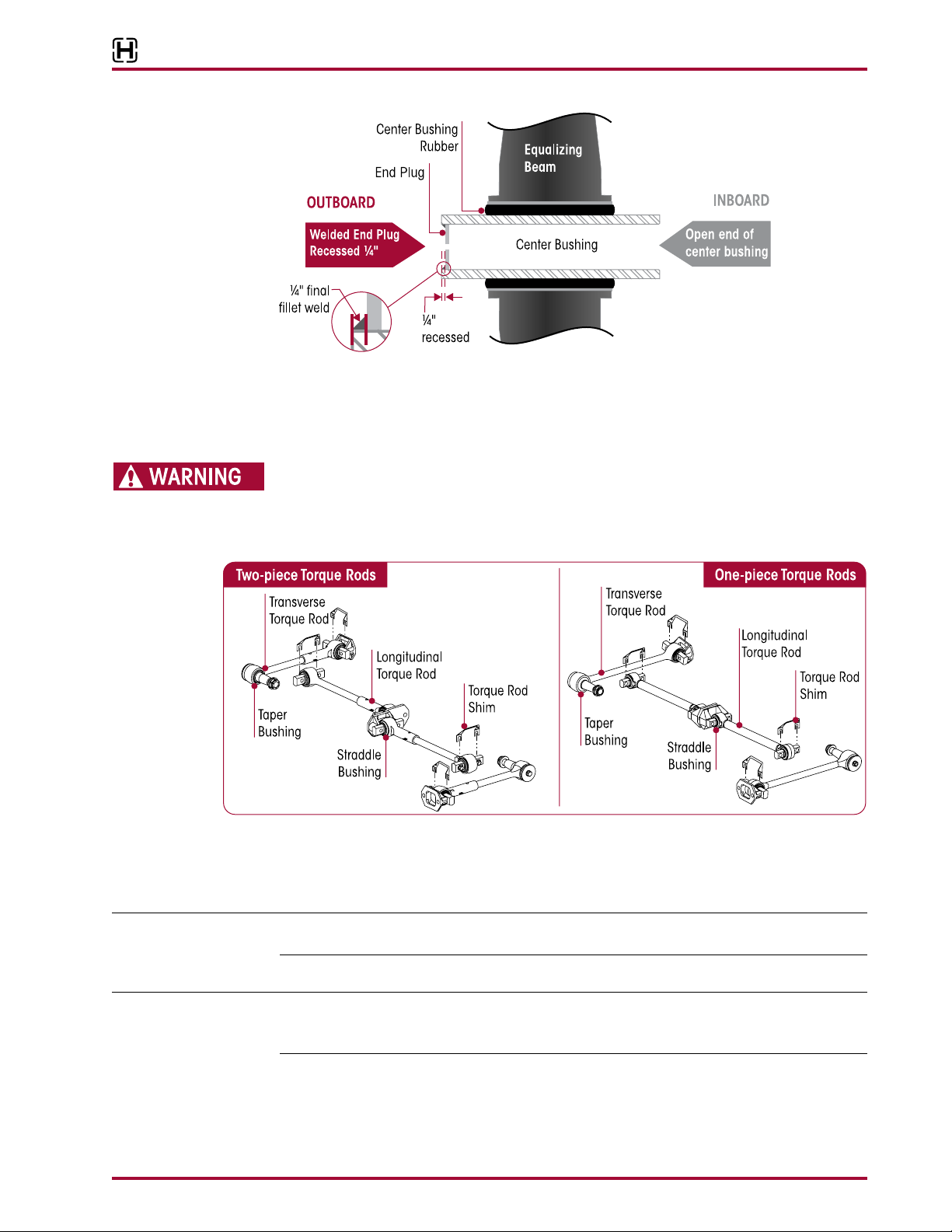
ULTIMAAX® for Fire and Rescue Vehicles
FIGURE 8-45
4. Position the end plug ¼" recessed in the center bushings and tack weld, see Figure 8-45.
5. Check end plug position, final weld shall be a ¼" fillet, see Figure 8-45.
TORQUE RODS
THE ULTIMAAX SUSPENSION INCORPORATES BOTH LONGITUDINAL AND TRANSVERSE TORQUE RODS
FOR VEHICLE STABILITY. IF THESE COMPONENTS ARE DISCONNECTED OR ARE NON-FUNCTIONAL THE
VEHICLE SHOULD NOT BE OPERATED. FAILURE TO DO SO CAN RESULT IN ADVERSE VEHICLE HANDLING
AND POSSIBLE TIRE CONTACT WITH THE FRAME OR THE SUSPENSION.
FIGURE 8-46
■
LONGITUDINAL TORQUE RODS
DISASSEMBLY
1. Chock the front wheels of the vehicle.
SERVICE HINT To remove all the load from the longitudinal torque rod, raise or lower the pinion as needed. This
will ease the removal of the longitudinal torque rod.
2. Support the pinion on the axle being serviced.
NOTE Prior to disassembly of the longitudinal torque rod, note the quantity and orientation of the longi-
tudinal torque rod shims. It is required that the longitudinal torque rod shims are installed in the
same orientation and location as removed to preserve the existing alignment, see Figure 8-46.
3. Remove the torque rod mounting fasteners and shims (if equipped).
4. Remove the fasteners that connect the longitudinal torque rod to the cross member and
axle brackets.
5. Remove longitudinal torque rod, see Figure 8-46.
17730-299 51 Component Replacement
Page 52
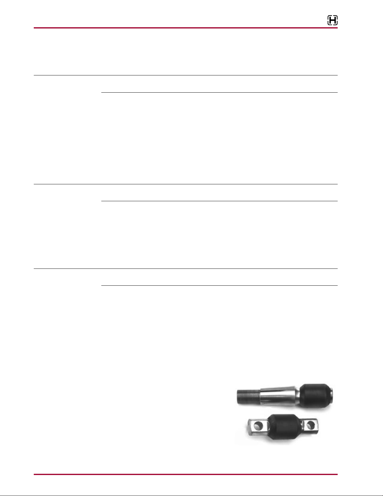
ULTIMAAX® for Fire and Rescue Vehicles
Taper Pin Bushing
ASSEMBLY
1. Install longitudinal torque rod.
2. Install the fasteners and any shims that were removed to the cross member and axle brackets.
NOTE Hendrickson recommends the use of Grade 8 bolts and Grade C locknuts. If flange head bolts and
locknuts are not used then hardened structural washers must be used under bolt heads and locknuts.
3. Tighten all fasteners to vehicle manufacturer’s torque specifications.
4. Verify proper pinion angle, and correct with drop in shims between the torque rod bar pin and
the cross member or axle bracket depending on the direction of adjustment needed. Contact
the vehicle manufacturer for proper pinion angle specifications.
5. Remove wheel chocks.
■
TRANSVERSE TORQUE RODS
DISASSEMBLY
1. Chock the front wheels of the vehicle.
SERVICE HINT Note the quantity and location of shims removed to maintain the lateral alignment of the axle
during assembly. See Alignment & Adjustments Section of this publication.
NOTE Hendrickson recommends the using Grade 8 bolts and Grade C locknuts for all torque rod
2. Remove the torque rod mounting fasteners.
3. Remove the transverse torque rod, see Figure 8-46.
4. Inspect the mounting surfaces for any wear or damage. Repair or replace as necessary.
ASSEMBLY
1. Install the transverse torque rod.
2. Install the mounting fasteners and any shims that were removed.
attachments.
3. Prior to tightening, ensure that the vehicle is at the proper ride height. Tighten all fasteners to
the required torque specification. Refer to original equipment manufacturer for specifications.
4. Check the lateral alignment. If not within vehicle manufacturer’s specified range, a lateral
alignment is necessary. See Lateral Alignment in the Alignment & Adjustments Section of this
publication.
5. Remove the wheel chocks.
TORQUE ROD BUSHINGS
■
ULTRA ROD PLUS, see Figure 8-47
FIGURE 8-47
You will need:
■
A vertical press with a capacity of at least
10tons
■
Shop made receiving tool and installation/
removal tool, refer to the Special Tools Selection
of this publication for more information
■
Funnel Tool No. 66086-000, refer to the Special
Tools Selection of this publication for more
information
Straddle Pin Bushing
Component Replacement 52 17730-299
Page 53
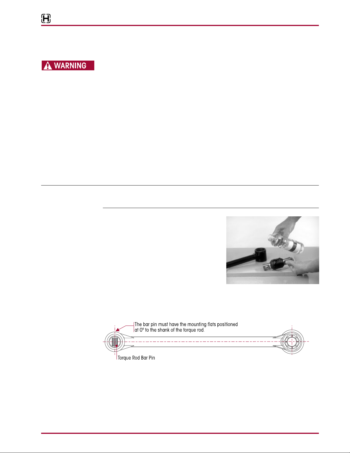
ULTIMAAX® for Fire and Rescue Vehicles
DISASSEMBLY
1. Remove torque rods as detailed in Torque Rod Disassembly instructions in this section.
DO NOT USE HEAT OR USE A CUTTING TORCH TO REMOVE THE BUSHINGS FROM THE TORQUE ROD. THE
USE OF HEAT WILL ADVERSELY AFFECT THE STRENGTH OF THE TORQUE ROD, HEAT CAN CHANGE THE
MATERIAL PROPERTIES. A COMPONENT DAMAGED IN THIS MANNER CAN RESULT IN ADVERSE VEHICLE
HANDLING AND POSSIBLE PERSONAL INJURY OR PROPERTY DAMAGE.
2. Support the torque rod end tube centered on the receiving tool. Be sure the torque rod is
squarely supported on the press bed for safe ty.
3. Push directly on the straddle mount bar pin, until the top of the pin is level with the top of
torque rod end tube. Place the push out tool directly on top of the bar pin and press until the
bushing clears the torque rod end tube.
4. Remove the fasteners from the tapered bar pin bushing, and support the torque rod end on
the receiving tool with the tapered stud pointing up and the end tube centered on the tool. Be
sure the torque rod is squarely supported on the press bed for safety.
5. Push directly on the tapered stud until the bushing clears the torque rod end tube.
ASSEMBLY
1. Clean and inspect the inner diameter of the torque rod end tubes.
NOTE DO NOT use paraffinic oil, or soap base lubricant. Such lubricants can cause adverse reactions
with the bushing, such as deterioration of the rubber, causing premature failure. Use ONLY a light
Naphthenic base oil, such as 60 SUS at 100°F.
FIGURE 8-48
2. Lubricate the inner diameter of the torque rod
end tubes and the new rubber bushings with
a light Naphthenic base oil, such as 60SUS at
100°F, see Figure 8-48.
3. Support the torque rod end tube centered on the
receiving tool. Ensure the torque rod is squarely
supported on the press bed for safety.
4. Place the assembly funnel tool centered on the
torque rod end hub, see Figure 8-50.
5. Place the torque rod bushing centered in the assembly funnel.
6. The straddle mount bar pin bushings must have the mounting flats positioned at zero degrees to
the shank of the torque rod, see Figure 8-49.
FIGURE 8-49
7. Press the bar pin through the assembly funnel into torque rod end hub until the rubber clears
the assembly funnel, see Figure 8-51.
8. Push directly on the straddle mount bar pin, or the tapered stud. The bushing must be centered within the end hubs of the torque rod.
■
When pushing in the new rubber bushings, overshoot the desired final position by approximately 3/16" (4.76 mm), see Figure 8-52.
17730-299 53 Component Replacement
Page 54
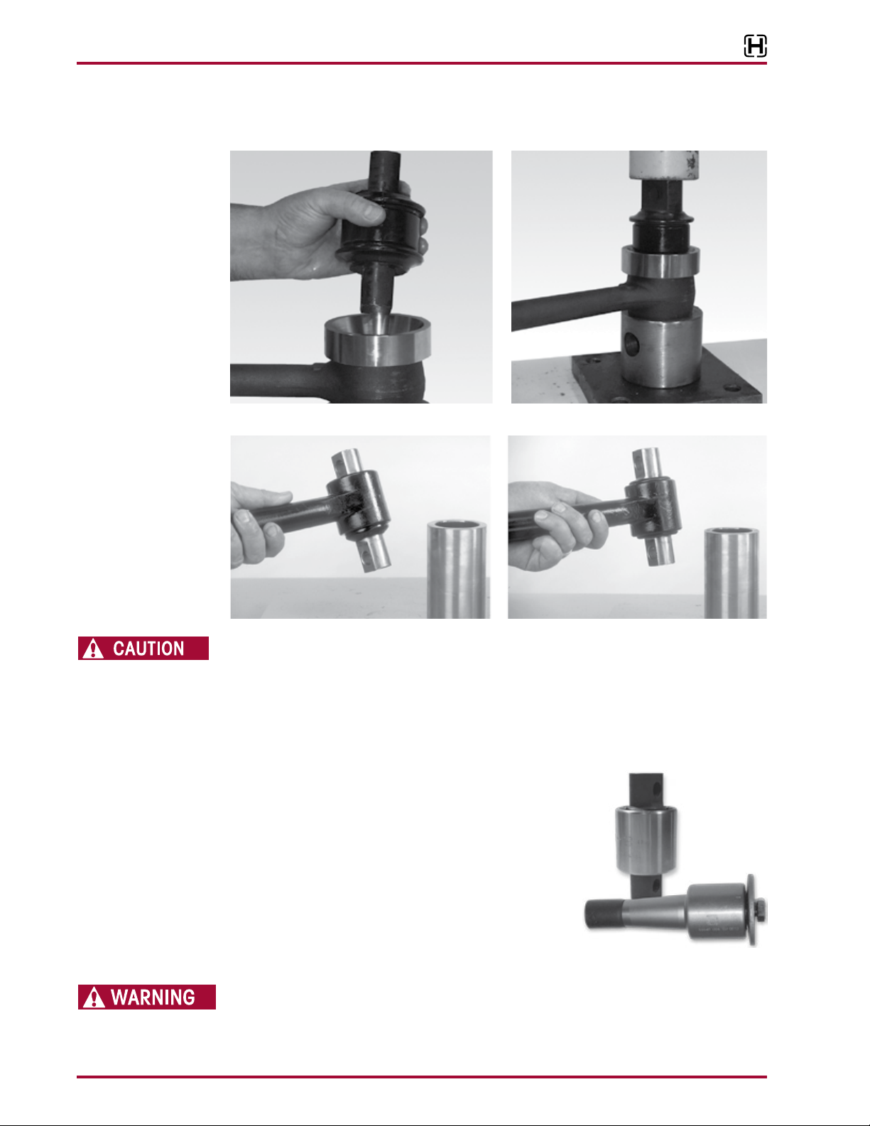
ULTIMAAX® for Fire and Rescue Vehicles
■
Push the rubber bushing again from the opposite side to center the rubber bushing within
the end hub, see Figure 8-53.
FIGURE 8-50 FIGURE 8-51
FIGURE 8-52 FIGURE 8-53
IF THE TORQUE ROD ASSEMBLY IS NOT ALLOWED THE ALLOTTED TIME FOR THE LUBRICANT TO DISSIPATE,
THE BUSHING MAY SLIDE FROM THE TORQUE ROD END HUB CAUSING THE BUSHING TO BE REMOVED
AND A NEW BUSHING RE-INSTALLED.
9. Wipe off the excess lubricant. Allow the lubricant four hours to dissipate prior to operating the
vehicle.
10. Install the torque rod as detailed in the Torque Rod Assembly instructions in this section.
FIGURE 8-54
■
XTRB, see Figure 8-54
You Will Need:
■
A vertical press with a capacity of at least 10 tons
■
Shop made receiving tool and installation / removal tool,
refer to the Special Tools Section of this publication for
more information.
BUSHING REMOVAL
1. Remove torque rods as detailed in Torque Rod
Disassembly instructions in this section.
DO NOT USE HEAT OR USE A CUTTING TORCH TO REMOVE THE BUSHINGS FROM THE TORQUE ROD.
THE USE OF HEAT WILL ADVERSELY AFFECT THE STRENGTH OF THE TORQUE ROD, HEAT CAN CHANGE
THE MATERIAL PROPERTIES. A COMPONENT DAMAGED IN THIS MANNER CAN RESULT IN THE ADVERSE
VEHICLE HANDLING AND POSSIBLE PERSONAL INJURY OR PROPERTY DAMAGE.
Component Replacement 54 17730-299
Page 55
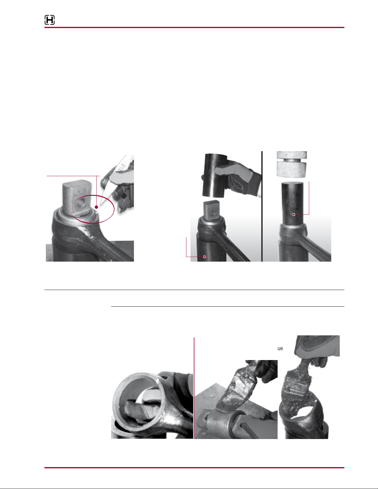
ULTIMAAX® for Fire and Rescue Vehicles
2. Straddle Mount Bar Pin Bushing —When servicing a straddle mount bar pin bushing assem-
bly, mark the clocking position of the straddle mount bar pin flats with a paint stick on the
torque rod end hub prior to disassembly, see Figure 8-55. This marking will serve as a guide
when installing the new bushing so the original clocking position can be retained.
3. Taper Pin Bushing — Remove the fastener and the concave washer from the taper pin
bushing.
4. Support the torque rod end hub and centered on the receiving tool (for a tapered bushing,
have the tapered stud pointing down). Ensure the torque rod is squarely supported on the
press bed for safe ty.
5. Install the removal tool, see Figure 8-56.
6. Press directly on the removal tool until the bushing clears the torque rod end hub, see
Figure8-57.
FIGURE 8-55 FIGURE 8-56 FIGURE 8-57
Mark the clocking position of the
bar pin ats with a paint stick
on the torque rod end hub
Torque Rod
Bushing
Installation /
Removal Tool
Torque Rod
Bushing
Receiving Tool
BUSHING INSTALLATION
1. Clean and inspect the inner diameter of the torque rod end hubs, see Figure 8-58.
SERVICE HINT DO NOT use a paraffinic oil, or soap base lubricant. Such lubricants can cause adverse reactions
with the bushing, causing premature failure.
2. Lubricate the inner diameter of the torque rod end hubs and the outer metal of new bushings
with NLGI #2 EP grease, see Figure 8-59.
FIGURE 8-58 FIGURE 8-59
Inspect and clean the inner
diameter of torque rod
end hubs
Apply NLGI #2-EP (Extreme Pressure)
lubricant to the inner diameter of torque
rod end hub and bushings
17730-299 55 Component Replacement
Page 56
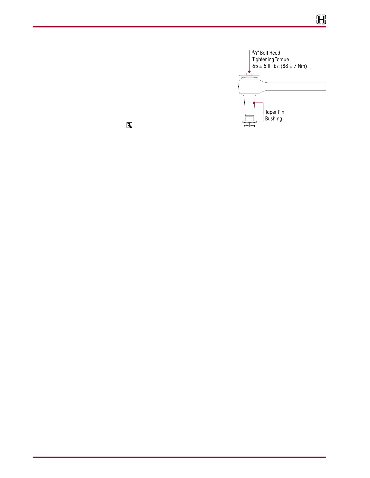
ULTIMAAX® for Fire and Rescue Vehicles
FIGURE 8-60
3. Support the torque rod end hub centered on the
receiving tool. Ensure the torque rod is squarely supported on the press bed for safety.
4. Straddle Mount — Place the straddle mount bushing in the end hub and re-align the bar pin bushings
to the mark made prior to removal as shown in
Figure8-55.
5. Taper Pin — Place the taper pin bushing in the end
hub with the taper pointing down. Tighten
head to 65 ± 5 torque, see Figure8-60.
6. Using the shop made tool, place the installation tool on the bushing and press in, see
Figure8-57.
7. Ensure the bushing is centered within the hub of the torque rod.
8. Wipe off the excess lubricant.
9. Replace torque rod assembly as detailed in the Transverse or Longitudinal Torque Rod
Component Replacement Section in this publication.
5
⁄8" bolt
Component Replacement 56 17730-299
Page 57

SECTION 9
Troubleshooting Guide
ULTIMAAX for Fire and Rescue Vehicles
TROUBLESHOOTING GUIDE
CONDITION POSSIBLE CAUSE CORRECTION
Damaged shock absorber Replace shock absorbers
Suspension has harsh or
bumpy ride
Vehicle leans
Irregular tire wear
Loose or missing suspension
fasteners
Frame hanger cracked
Saddle leg to equalizing
beam contact
Damaged progressive load spring Replace progressive load springs, must be replaced in pairs
Damaged shear spring Replace shear spring
Vehicle overloaded Redistribute or reduce load to correct weight
Damaged progressive load spring Replace progressive load springs, must be replaced in pairs
Damaged shear spring Replace shear spring
Bent cross tube Replace cross tube
Weight bias Redistribute load to correct weight bias
Incorrect axle alignment
Bent cross tube Replace cross tube
Damaged, bent, cracked suspension
component
Suspension is overloaded
Improper torque or over torque
Suspension is overloaded
Loose or missing suspension fasteners
Damaged frame hanger assembly Replace frame hanger assembly
Damaged, bent, worn, or cracked
suspension component(s)
Cross tube bent or missing Replace cross tube
Loose or worn saddle hex bolts Replace saddle hex bolts, inspect mating components
Saddles not center on equalizing beam Center saddles on the equalizing beam
Saddles not center on center bushing Replace center bushing
ULTIMAAX® for Fire and Rescue Vehicles
Axle alignment is permanently set at the time of vehicle
manufacture. Contact vehicle manufacturer.
Replace damaged component
Reduce and/or redistribute load to correct weight
Replace and/or properly tighten fasteners to the proper torque
specification
Increase inspection interval of fasteners
Replace and/or properly tighten fasteners to the proper torque
specification
Replace frame hanger assembly
Reduce and/or redistribute load to correct weight
Replace frame hanger assembly
Increase inspection interval of fasteners
Replace fasteners and/or properly tighten fasteners to the
proper torque specification
Replace damaged component
17730-299 57 Component Replacement
Page 58
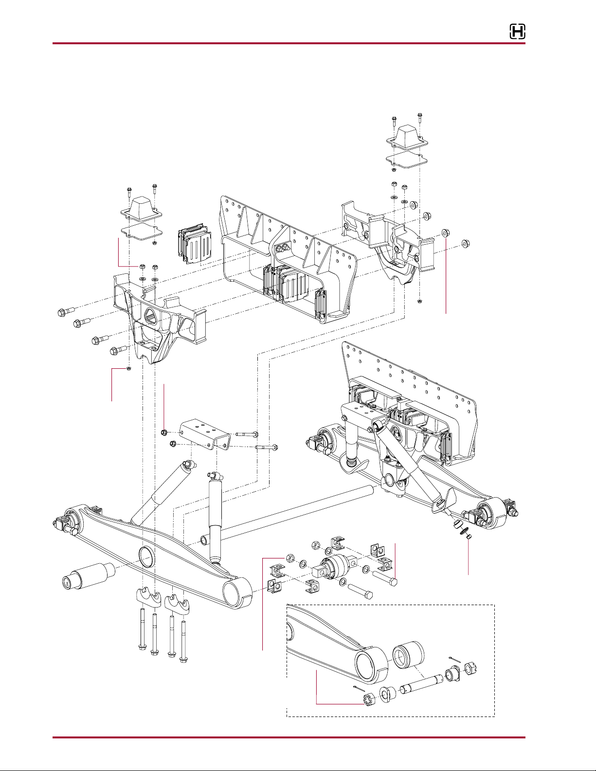
ULTIMAAX® for Fire and Rescue Vehicles
(109 ± 19 Nm)
SECTION 10
Torque Specifications
1.
200 ± 20 ft. lbs
(270 ± 30 Nm)
Hendrickson Recommended Torque Values Provided in
Foot Pounds and in Newton Meters
3.
325 ft. lbs (440 Nm)
+ 90° Rotation
OR
560 ± 30 ft. lbs
(760 ± 40 Nm)
30 ± 2 ft. lbs
(41 ± 3 Nm)
2.
6.
170 ± 20 ft. lbs
(231 ± 27 Nm)
525 ± 75 ft. lbs
4a.
(712 ± 102 Nm)
4b.
575 ± 75 ft. lbs
(780 ± 102 Nm)
63K Beam End Conguration
7.
80 ± 10 ft. lbs
125 ft. lbs (170 Nm) + 90° Rotation
Component Replacement 58 17730-299
700 ± 50 ft. lbs
OR
(949 ± 68 Nm)
5.
Page 59

ULTIMAAX® for Fire and Rescue Vehicles
ULTIMAAX for Fire and Rescue Vehicles
HENDRICKSON RECOMMENDED TORQUE SPECIFICATIONS
FASTENER TORQUE VALUE
NO. COMPONENT
*QUANTITY SIZE
1 Saddle Assembly to Saddle Cap 8 M16 200 ± 20 270 ± 30
2 Saddle Assembly to Progressive Load Spring 8 M10 30 ± 2 41 ± 3
FOOT
POUNDS
NEWTON
METERS
325
3 Saddle Assembly Halves 8 M20
4a
End Bushing – Bar Pin Style
4b At Bolt Head 8 1" 575 ± 75 780 ± 102
5 End Bushing – Adapter Style 4 1
6 Shock Absorber to Upper Shock Bracket 4 M16 170 ± 20 231 ± 27
7 Shock Absorber to Lower Shock Bracket 4
NOTE: * Quantities shown are per suspension.
** Torque values shown in this publication apply only if Hendrickson supplied fasteners are used. If non Hendrickson fasteners are
used, follow the torque specication listed in the vehicle manufacturer’s service manual.
At Locknut 8 1" 525 ± 75 712 ± 102
7
⁄8"
5
/8" 80 ± 10 109 ± 14
+ 90° rotation
or 560 ± 30
125
+ 90° rotation
or 700 ± 50
440
+ 90° rotation
or 760 ± 40
170
+ 90° rotation
or 949 ± 68
17730-299 59 Component Replacement
Page 60
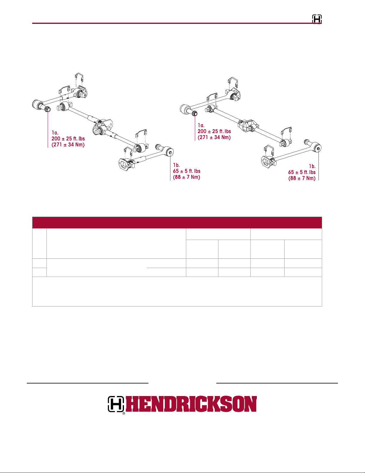
ULTIMAAX® for Fire and Rescue Vehicles
One and Two-piece Torque Rods
Hendrickson Recommended Torque Values Provided in
Foot Pounds and in Newton Meters
ULTIMAAX for Fire and Rescue Vehicles
HENDRICKSON RECOMMENDED TORQUE SPECIFICATIONS
FASTENER TORQUE VALUE
NO. COMPONENT
*QUANTITY SIZE
1a
Transverse Torque Rod
1b At the Bolt Head 2
NOTE: * Quantities shown are per suspension.
** Torque values shown in this publication apply only if Hendrickson supplied fasteners are used. If non Hendrickson fasteners are
used, follow the torque specication listed in the vehicle manufacturer’s service manual.
At the Locknut 2 1¼" 200 ± 25 271 ± 34
5
/8" 65 ± 5 88 ± 7
www.hendrickson-intl.com
FOOT
POUNDS
NEWTON
METERS
Truck Commercial Vehicle Systems 1.866.755.5968 (Toll-free U.S. and Canada)
800 South Frontage Road 1.630.910.2800 (Outside U.S. and Canada)
Woodridge, IL 60517-4904 USA Fax 1.630.910.2899
17730-299 Rev B 07-18 © 2016 – 2018 Hendrickson USA, L.L.C. All Rights Reserved Printed in United States of America
Information contained in this literature was accurate at the time of publication. Product changes may have been made after the copyright date that are not reected.
 Loading...