

Hendrickson PRIMAAX EX, PRIMAAX Technical Procedures
TABLE OF CONTENTS
PRIMAAX® EX / PRIMAAX® for
Volvo Vehicles
SUBJECT: Service Instructions
LIT NO: 17730-254
DATE: March 2012 REVISION: B
Section 1 Introduction . . . . . . . . . . . . . . . . . . . . . . . . 2
Section 2 Product Description . . . . . . . . . . . . . . . . . 2
Section 3 Important Safety Notice . . . . . . . . . . . . . . 4
Section 4 Special Tools . . . . . . . . . . . . . . . . . . . . . . . 9
Section 5 Parts Lists . . . . . . . . . . . . . . . . . . . . . . . . . 12
PRIMAAX EX . . . . . . . . . . . . . . . . . . . . . . . . .12
PRIMAAX . . . . . . . . . . . . . . . . . . . . . . . . . . . 14
Section 6 Preventive Maintenance. . . . . . . . . . . . .16
Areas of Inspection . . . . . . . . . . . . . . . . . . .16
Hendrickson Recommended
Preventive Maintenance Intervals . . . . . . . .16
Component Inspection . . . . . . . . . . . . . . . . 18
U-bolt Fasteners . . . . . . . . . . . . . . . . . . . . . 19
Transverse Torque Rods . . . . . . . . . . . . . . . .20
Longitudinal Torque Rods . . . . . . . . . . . . . . 20
Shock Absorber . . . . . . . . . . . . . . . . . . . . . . 21
Air Fitting Inspection . . . . . . . . . . . . . . . . . . 22
Section 8 Component Replacement . . . . . . . . . . . 29
Fasteners . . . . . . . . . . . . . . . . . . . . . . . . . . 29
Height Control Valve . . . . . . . . . . . . . . . . . . 29
Air Spring . . . . . . . . . . . . . . . . . . . . . . . . . . 29
Shock Absorber . . . . . . . . . . . . . . . . . . . . . . 31
Transverse Torque Rod . . . . . . . . . . . . . . . . . 32
Longitudinal Torque Rod . . . . . . . . . . . . . . . 32
Longitudinal Torque Rod Bushing . . . . . . . . . 33
Support Beam Assembly and Cross Tube . . . 34
U-beam Assembly . . . . . . . . . . . . . . . . . . . . 35
D-pin Bushing . . . . . . . . . . . . . . . . . . . . . . . 38
QUIK-ALIGN Pivot Bushing . . . . . . . . . . . . . . 43
Top Pad . . . . . . . . . . . . . . . . . . . . . . . . . . . . 44
Bottom Cap and Axle Spacer . . . . . . . . . . . . 47
Axle Stops . . . . . . . . . . . . . . . . . . . . . . . . . . 50
Frame Hanger . . . . . . . . . . . . . . . . . . . . . . 50
Section 9 Torque Speci cations . . . . . . . . . . . . . . . 54
PRIMAAX EX . . . . . . . . . . . . . . . . . . . . . . . . . 54
PRIMAAX . . . . . . . . . . . . . . . . . . . . . . . . . . 56
Section 7 Alignment & Adjustments . . . . . . . . . . . 23
Ride Height Adjustment . . . . . . . . . . . . . . . . 23
Lateral Alignment . . . . . . . . . . . . . . . . . . . . 23
Axle Pinion Angle . . . . . . . . . . . . . . . . . . . .24
Drive Axle Alignment Inspection Procedure
(Scrub Angle) . . . . . . . . . . . . . . . . . . . . . . . 24
Alignment Adjustment Instructions . . . . . . . 26
Pinion Angle Adjustment . . . . . . . . . . . . . . . 28
Section 10 Troubleshooting Guide . . . . . . . . . . . . . . 58
PRIMAAX® EX / PRIMAAX® for Volvo Vehicles
SECTION 1
Introduction
This publication is intended to acquaint and assist maintenance personnel in the preventive
maintenance, service, repair and rebuild of the PRIMAAX® EX / PRIMAAX® suspension systems
as installed on applicable Volvo Vehicles.
NOTE Use only Genuine
It is important to read and understand the entire Technical Procedure publication prior to performing any maintenance, service, repair, or rebuild of this product. The information in this
publication contains parts lists, safety information, product specifications, features, proper maintenance, service, repair and rebuild instructions for the PRIMAAXEX / PRIMAAX Suspensions for
Volvo vehicles.
Hendrickson reserves the right to make changes and improvements to its products and
publications at any time. Contact Hendrickson Tech Services for information on the latest version of this manual at 1-866-755-5968 (toll-free U.S. and Canada), 630-910-2800 (outside U.S.
and Canada) or e-mail: techservices@hendrickson-intl.com.
The latest revision of this publication is also available online at
www.hendrickson-intl.com
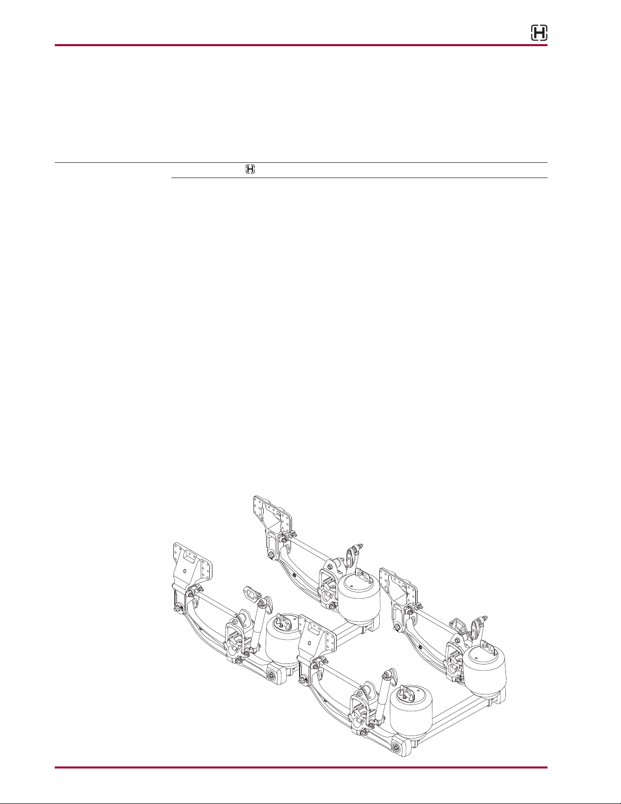
SECTION 2
Product Description
PRIMAAX EX is intended for vocational and heavy-haul vehicle applications including, but
not limited to: truck, tractor, dump, mixer, refuse, logging, platform, fire/rescue, specialty
and vehicles equipped with outriggers as approved by Hendrickson and vehicle manufacturer — contact Hendrickson or vehicle manufacturer for specific application approval and
additional information.
Hendrickson parts for servicing this suspension system.
Introduction 2 17730-254

PRIMAAX® EX / PRIMAAX® for Volvo Vehicles
■
Genuine Hendrickson torque rods — Optimized configuration helps improve handling and
roll stiffness for expanded applications.
■
QUIK-ALIGN® — Allows for easy axle alignment without shims. Reduces maintenance time
and helps extend tire life.
■
Air springs — Large volume, low frequency design for premium ride quality. Advanced
design air springs lift and support the load with less air pressure.
■
Structural beams / cross beams — Cast structural beams form a solid connection with
the square cross brace to form a rigid torsion and stabilizer system. Redesigned structural
beams utilize premium materials and are proven in some of the most challenging environments. Integrated beam end cap allows for a maintenance-free connection with the cross
beam for increased uptime. Robust rubber bushings improve service life and eliminate
lubrication requirements.
■
Heavy-duty shock absorbers — Positioned and tuned for optimum damping characteristics.
■
Axle connections — D-pin axle connection decreases torsional axle stress for reduced maintenance and increased joint integrity. Integrated axle stop contact pads reduce axle stress.
PRIMAAX EX SPECIFICATIONS FOR VOLVO VEHICLES
Capacity 46,000 lbs. 69,000 lbs.
Axle Configuration Tandem Tridem
1
Site Travel Rating
Axle Travel
Ground Clearance 9.25" 9.25"
Lift Axles Approved Approved
Ride Heights
Engine Torque Restrictions None None
Axle Spacing 52" - 72.5" 108"
60,000 lbs. 90,000 lbs.
2
7.0", 7.5" 7.0", 7.5"
3
8.5", 10" 8.5", 10"
1. Operators using vehicles equipped with liftable push or tag axles must not exceed published ratings. Ratings are
limited to no more than five percent of vehicle operation at a speed not to exceed five mph. Liftable pusher or tag
axles should be raised (or unloaded) to improve vehicle maneuverability in off-road use or when vehicle is empty.
Site travel ratings are consistent with specifications and must not be exceeded.
2. Axle travel may be limited by vehicle manufacturer; axle stop settings may restrict suspension’s articulation.
3. For different ride height options, please contact Hendrickson, your vehicle manufacturer or authorized vehicle
dealer for further information.
U.S. and foreign patents granted and/or pending.
17730-254 3 Product Description
PRIMAAX® EX / PRIMAAX® for Volvo Vehicles
SECTION 3
Important Safety Notice
Proper maintenance, service and repair are important to the reliable operation of the suspension. The procedures recommended by Hendrickson and described in this technical publication
are methods of performing such maintenance, service and repair.
The warnings and cautions should be read carefully to help prevent personal injury and to
assure that proper methods are used. Improper maintenance, service or repair may damage
the vehicle, cause personal injury, render the vehicle unsafe in operation, or void manufacturer’s
warranty.
Failure to follow the safety precautions in this manual can result in personal injury and/or property damage. Carefully read and understand all safety related information within this publication,
on all decals and all such materials provided by the vehicle manufacturer before conducting any
maintenance, service or repair.
■
EXPLANATION OF SIGNAL WORDS
Hazard “Signal Words” (Danger • Warning • Caution) appear in various locations throughout
this publication. Information accented by one of these signal words must be observed to help
minimize the risk of personal injury to service personnel, or possibility of improper service methods which may damage the vehicle or render it unsafe.
This is the safety alert symbol. It is used to alert you to potential personal injury haz-
ards. Obey all safety messages that follow this symbol to avoid possible injury or
death.
The following definitions indicate the use of these signal words as they appear throughout the
publication.
INDICATES AN IMMINENTLY HAZARDOUS SITUATION WHICH, IF NOT AVOIDED, WILL RESULT IN
SERIOUS INJURY OR DEATH.
INDICATES A POTENTIAL HAZARDOUS SITUATION WHICH, IF NOT AVOIDED, CAN RESULT IN SERIOUS
INJURY OR DEATH.
INDICATES A POTENTIAL HAZARDOUS SITUATION WHICH, IF NOT AVOIDED, MAY RESULT IN MINOR
OR MODERATE INJURY, OR PROPERTY DAMAGE.
NOTE An operating procedure, practice condition, etc. which is essential to emphasize.
SERVICE HINT A helpful suggestion, which will make the servicing being performed a little easier and/or
faster.
Also note that particular service operations may require the use of special tools designed for
specific purposes. These special tools can be found in the Special Tools Section of this publication.
The torque symbol alerts you to tighten fasteners to a specified torque value. Refer to Torque
Specifications Section of this publication.
Important Safety Notice 4 17730-254
■
SAFETY PRECAUTIONS
FASTENERS
DISCARD USED FASTENERS. ALWAYS USE NEW FASTENERS TO COMPLETE A REPAIR. FAILURE TO
DO SO COULD RESULT IN FAILURE OF THE PART OR MATING PARTS, LOSS OF VEHICLE CONTROL,
PERSONAL INJURY, OR PROPERTY DAMAGE.
LOOSE OR OVER TORQUED FASTENERS CAN CAUSE COMPONENT DAMAGE, LOSS OF VEHICLE
CONTROL, PROPERTY DAMAGE, OR SEVERE PERSONAL INJURY. MAINTAIN CORRECT TORQUE
VALUE AT ALL TIMES. CHECK TORQUE VALUES ON A REGULAR BASIS AS SPECIFIED, USING A
TORQUE WRENCH THAT IS REGULARLY CALIBRATED. TORQUE VALUES SPECIFIED IN THIS TECHNICAL
PUBLICATION ARE FOR HENDRICKSON SUPPLIED FASTENERS ONLY. IF NON HENDRICKSON
FASTENERS ARE USED, FOLLOW TORQUE SPECIFICATION LISTED IN THE VEHICLE MANUFACTURER’S
SERVICE MANUAL.
QUIK-ALIGN FASTENERS
DISCARD USED QUIK-ALIGN FASTENERS. ALWAYS USE NEW QUIK-ALIGN FASTENERS TO COMPLETE A
REPAIR. FAILURE TO DO SO COULD RESULT IN FAILURE OF THE PART, OR MATING COMPONENTS, LOSS
OF VEHICLE CONTROL, PERSONAL INJURY, OR PROPERTY DAMAGE.
DO NOT ASSEMBLE QUIK-ALIGN JOINT WITHOUT THE PROPER FASTENERS. USE ONLY H-COATED
FASTENERS TO SUSTAIN PROPER CLAMP FORCE. FAILURE TO DO SO CAN CAUSE LOSS OF VEHICLE
CONTROL, PROPERTY DAMAGE OR PERSONAL INJURY AND VOID WARRANTY. ENSURE THAT THE
QUIK-ALIGN FASTENER’S TORQUE VALUES ARE SUSTAINED AS RECOMMENDED IN THE TORQUE
SPECIFICATIONS SECTION OF THIS PUBLICATION. FAILURE TO DO SO CAN CAUSE LOSS OF VEHICLE
CONTROL RESULTING IN PERSONAL INJURY OR PROPERTY DAMAGE.
PRIMAAX® EX / PRIMAAX® for Volvo Vehicles
LOAD CAPACITY
ADHERE TO THE PUBLISHED CAPACITY RATINGS FOR THE SUSPENSION. ADD-ON AXLE ATTACHMENTS
AND OTHER LOAD TRANSFERRING DEVICES CAN INCREASE THE SUSPENSION LOAD ABOVE ITS
RATED AND APPROVED CAPACITIES, WHICH CAN RESULT IN COMPONENT DAMAGE AND LOSS OF
VEHICLE CONTROL, POSSIBLY CAUSING PERSONAL INJURY OR PROPERTY DAMAGE.
MODIFYING COMPONENTS
DO NOT MODIFY OR REWORK PARTS WITHOUT AUTHORIZATION FROM HENDRICKSON. DO NOT
SUBSTITUTE REPLACEMENT COMPONENTS NOT AUTHORIZED BY HENDRICKSON. USE OF MODIFIED,
REWORKED, SUBSTITUTE OR REPLACEMENT PARTS NOT AUTHORIZED BY HENDRICKSON MAY
NOT MEET HENDRICKSON’S SPECIFICATIONS, AND CAN RESULT IN FAILURE OF THE PART, LOSS
OF VEHICLE CONTROL, POSSIBLE PERSONAL INJURY OR PROPERTY DAMAGE, AND WILL VOID
WARRANTY. USE ONLY HENDRICKSON AUTHORIZED REPLACEMENT PARTS.
TORCH/WELDING
DO NOT USE A CUTTING TORCH TO REMOVE ANY FASTENERS. THE USE OF HEAT ON SUSPENSION
COMPONENTS WILL ADVERSELY AFFECT THE STRENGTH OF THESE PARTS. A COMPONENT
DAMAGED IN THIS MANNER CAN RESULT IN THE LOSS OF VEHICLE CONTROL AND POSSIBLE
PERSONAL INJURY OR PROPERTY DAMAGE.
EXERCISE EXTREME CARE WHEN HANDLING OR PERFORMING MAINTENANCE IN THE AREA OF
THE SUPPORT BEAM. DO NOT CONNECT ARC WELDING GROUND LINE TO THE SUPPORT BEAM.
DO NOT STRIKE AN ARC WITH THE ELECTRODE ON THE SUPPORT BEAM. DO NOT USE HEAT NEAR
THE SUPPORT BEAM ASSEMBLY. DO NOT NICK OR GOUGE THE SUPPORT BEAM. SUCH IMPROPER
ACTIONS CAN DAMAGE THE SUPPORT BEAM ASSEMBLY AND CAUSE LOSS OF VEHICLE CONTROL
AND POSSIBLE PERSONAL INJURY OR PROPERTY DAMAGE.
17730-254 5 Important Safety Notice
PRIMAAX® EX / PRIMAAX® for Volvo Vehicles
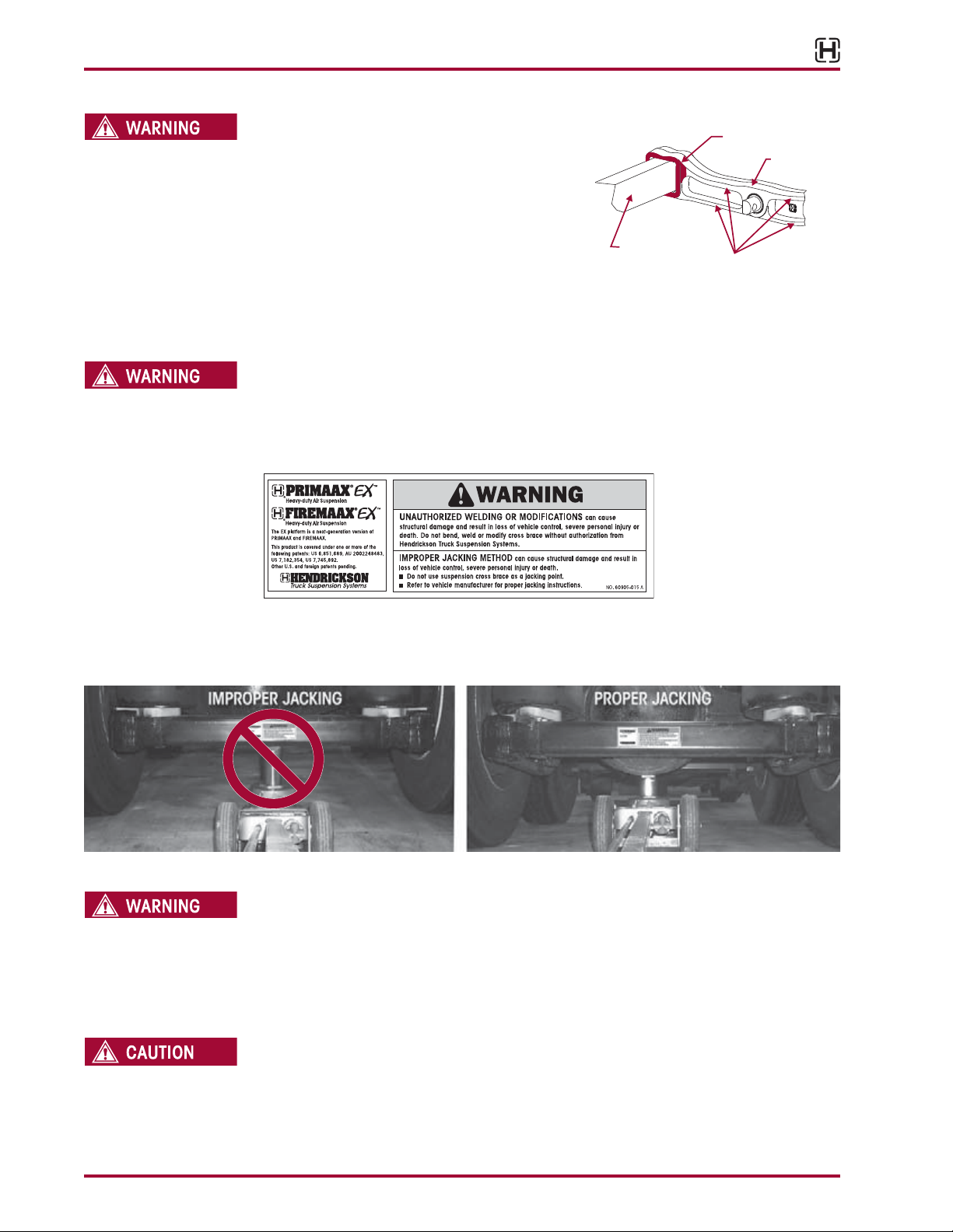
CROSS TUBE, SUPPORT BEAM AND U-BEAM ASSEMBLY FIGURE 3-1
WHEN SEPARATING THE U-BEAM ASSEMBLY, PROTECT
THE CROSS TUBE BY PLACING A PIECE OF PLYWOOD
AGAINST OR CARDBOARD AROUND THE CROSS
TUBE. CAREFULLY DISLODGE THE CROSS TUBE
FROM THE SUPPORT BEAM WITH A LONG HANDLED
SLEDGE HAMMER BY APPLYING BLUNT FORCE ON
THE SUPPORT BEAM DIRECTLY IN FRONT OF THE
INBOARD TOP CORNER JOINT. ALL BLUNT FORCE
MUST BE APPLIED FLUSH TO THE THICKEST PART OF THE SUPPORT BEAM. FAILURE TO STRIKE THE
SUPPORT BEAM SQUARELY MAY RESULT IN COMPONENT DAMAGE, PREMATURE FAILURE AND VOID
WARRANTY, SEE FIGURE 3-1.
CROSS TUBE
IMPROPER JACKING METHODS CAN CAUSE STRUCTURAL DAMAGE (SEE SAFETY DECAL, FIGURE
3-2) AND RESULT IN LOSS OF VEHICLE CONTROL, SEVERE PERSONAL INJURY OR DEATH AND WILL
VOID HENDRICKSON’S WARRANTY.
FIGURE 3-2
Cross Brace
REPLACE ANY SAFETY
DECALS THAT ARE FADED,
TORN, MISSING, ILLEGIBLE,
OR OTHERWISE DAMAGED.
CONTACT HENDRICKSON
TO ORDER REPLACEMENT
LABELS.
Target Area
Support Beam
Do not strike the
Support Beam Flanges
■
DO NOT USE THE SUSPENSION CROSS TUBE AS A JACKING POINT, SEE FIGURE 3-3.
■
REFER TO VEHICLE MANUFACTURER FOR PROPER JACKING INSTRUCTIONS, SEE FIGURE 3-4.
FIGURE 3-3 FIGURE 3-4
SHOCK ABSORBERS
THE SHOCK ABSORBERS ARE THE REBOUND TRAVEL STOPS FOR THE SUSPENSION. ANYTIME THE
AXLE ON A PRIMAAX EX / PRIMAAX SUSPENSION IS SUSPENDED IT IS MANDATORY THAT THE
SHOCK ABSORBERS REMAIN CONNECTED. FAILURE TO DO SO CAN CAUSE THE AIR SPRINGS TO
SEPARATE FROM THE PISTON AND RESULT IN PREMATURE AIR SPRING FAILURE. REPLACEMENT OF
SHOCK ABSORBERS WITH NON-HENDRICKSON PARTS CAN ALTER THE REBOUND TRAVEL OF THE
SUSPENSION.
THE UPPER SHOCK BOLT MUST BE INDEXED INTO THE RECESSED HEX BORE OF THE UPPER SHOCK
MOUNTING BRACKET FOR PROPER FASTENER INSTALLATION. FAILURE TO DO SO CAN CAUSE THE
SHOCK FASTENERS TO BECOME LOOSE AND CAUSE PREMATURE COMPONENT DAMAGE.
Important Safety Notice 6 17730-254
TRANSVERSE TORQUE RODS
PRIMAAX EX / PRIMAAX SUSPENSIONS INCORPORATE TRANSVERSE RODS FOR VEHICLE STABILITY. IF
THESE COMPONENTS ARE DISCONNECTED OR ARE NON-FUNCTIONAL, THE VEHICLE SHOULD NOT
BE OPERATED. FAILURE TO DO SO CAN RESULT IN ADVERSE VEHICLE HANDLING, LOSS OF VEHICLE
CONTROL, POSSIBLE TIRE CONTACT WITH THE FRAME, PREMATURE COMPONENT DAMAGE, OR
SEVERE PERSONAL INJURY.
PRIMAAX® EX / PRIMAAX® for Volvo Vehicles
PRIOR TO AND DURING DEFLATION AND INFLATION OF THE AIR SUSPENSION SYSTEM, ENSURE ALL
AIR SPRING INFLATION
AIR SPRING LOWER MOUNTING STUDS
AIR SPRING PRESSURE RETENTION
AIR SPRING INFLATION AND DEFLATION
PRIOR TO DISASSEMBLY OF THE SUSPENSION, AIR SPRING ASSEMBLIES MUST BE DEFLATED.
UNRESTRICTED AIR SPRING ASSEMBLIES CAN VIOLENTLY SHIFT. DO NOT INFLATE AIR SPRING
ASSEMBLIES WHEN THEY ARE UNRESTRICTED. AIR SPRING ASSEMBLIES MUST BE RESTRICTED
BY SUSPENSION OR OTHER ADEQUATE STRUCTURE. DO NOT INFLATE BEYOND PRESSURES
RECOMMENDED BY AIR SPRING MANUFACTURER, CONTACT HENDRICKSON TECHNICAL SERVICES
FOR DETAILS. IMPROPER USE OR OVER INFLATION MAY CAUSE AIR SPRING ASSEMBLIES TO BURST,
CAUSING PROPERTY DAMAGE AND/OR SEVERE PERSONAL INJURY.
PERSONNEL AND EQUIPMENT ARE CLEAR FROM UNDER THE VEHICLE AND AROUND THE SERVICE
AREA, FAILURE TO DO SO CAN CAUSE SERIOUS PERSONAL INJURY, DEATH, OR PROPERTY DAMAGE.
INFLATE THE SUSPENSION SLOWLY AND MAKE SURE THAT THE RUBBER BLADDER OF THE AIR
SPRING INFLATES UNIFORMLY AND IS NOT BINDING. FAILURE TO DO SO CAN CAUSE DAMAGE TO
THE UPPER AIR SPRING MOUNTING BRACKET AND VOID WARRANTY.
IF THE AIR SPRING IS BEING REMOVED, IT IS MANDATORY TO LUBRICATE THE LOWER AIR SPRING
FASTENERS WITH PENETRATING OIL AND REMOVE WITH HAND TOOLS TO PREVENT DAMAGE TO THE
LOWER AIR SPRING MOUNTING STUD. FAILURE TO DO SO CAN CAUSE COMPONENT DAMAGE AND
VOID WARRANTY.
SOME VEHICLE APPLICATIONS, SUCH AS VEHICLES EQUIPPED WITH OUTRIGGERS, RETAIN SOME
PRESSURE IN THE AIR SPRINGS AT ALL TIMES. PRIOR TO PERFORMING ANY MAINTENANCE, SERVICE,
OR REPAIR OF THE SUSPENSION, VERIFY EACH AIR SPRING IS COMPLETELY DEFLATED. FAILURE TO
DO SO COULD RESULT IN SERIOUS PROPERTY DAMAGE AND/OR SEVERE PERSONAL INJURY.
FAILURE TO PRESS THE AIR SPRING AGAINST THE UNDERSIDE OF THE FRAME WHILE TIGHTENING
THE UPPER AIR SPRING BRACKET CAN RESULT IN COMPONENT DAMAGE AND PERSONAL INJURY
OR PROPERTY DAMAGE.
WORK SITE DUMPING
WHEN THE TRUCK/TRAILER BODY/BOOM/AND OR ATTACHMENT IS LIFTED IT IS MANDATORY TO
COMPLETELY EXHAUST THE AIR FROM THE REAR SUSPENSION SYSTEM TO HELP PROVIDE STABILITY
WHEN LIFTED. FAILURE TO DO SO CAN RESULT IN LOSS OF VEHICLE CONTROL, ROLL-OVER,
OR VEHICLE INSTABILITY, POSSIBLY CAUSING SEVERE PERSONAL INJURY, PROPERTY DAMAGE,
OR DEATH. FIRST RAISE ANY AUXILIARY AXLES AND THEN EXHAUST ALL PRESSURE FROM REAR
TRACTOR / TRAILER AND TRUCK AIR SUSPENSION SYSTEMS PRIOR TO RAISING THE BODY / BOOM
OR ATTACHMENTS. FOLLOW THE VEHICLE MANUFACTURER’S OPERATING INSTRUCTIONS FOR
MAINTAINING PROPER STABILITY.
PERSONAL PROTECTIVE EQUIPMENT
ALWAYS WEAR PROPER EYE PROTECTION AND OTHER REQUIRED PERSONAL PROTECTIVE
EQUIPMENT TO HELP PREVENT PERSONAL INJURY WHEN PERFORMING VEHICLE MAINTENANCE,
REPAIR OR SERVICE.
17730-254 7 Important Safety Notice

PRIMAAX® EX / PRIMAAX® for Volvo Vehicles
PROCEDURES AND TOOLS
A TECHNICIAN USING A SERVICE PROCEDURE OR TOOL WHICH HAS NOT BEEN RECOMMENDED
BY HENDRICKSON MUST FIRST SATISFY HIMSELF THAT NEITHER HIS SAFETY NOR THE VEHICLE’S
SAFETY WILL BE JEOPARDIZED BY THE METHOD OR TOOL SELECTED. INDIVIDUALS DEVIATING IN
ANY MANNER FROM THE INSTRUCTIONS PROVIDED WILL ASSUME ALL RISKS OF CONSEQUENTIAL
PERSONAL INJURY OR DAMAGE TO EQUIPMENT INVOLVED.
PARTS CLEANING
SOLVENT CLEANERS CAN BE FLAMMABLE, POISONOUS, AND CAUSE BURNS. TO HELP AVOID
SERIOUS PERSONAL INJURY, CAREFULLY FOLLOW THE MANUFACTURER’S PRODUCT INSTRUCTIONS
AND GUIDELINES AND THE FOLLOWING PROCEDURES:
1. WEAR PROPER EYE PROTECTION.
2. WEAR CLOTHING THAT PROTECTS YOUR SKIN.
3. WORK IN A WELL-VENTILATED AREA.
4. DO NOT USE GASOLINE OR SOLVENTS THAT CONTAIN GASOLINE. GASOLINE CAN EXPLODE.
5. HOT SOLUTION TANKS OR ALKALINE SOLUTIONS MUST BE USED CORRECTLY. FOLLOW THE
MANUFACTURER’S RECOMMENDED INSTRUCTIONS AND GUIDELINES CAREFULLY TO HELP
PREVENT PERSONAL ACCIDENT OR INJURY.
DO NOT USE HOT SOLUTION TANKS OR WATER AND ALKALINE SOLUTIONS TO CLEAN GROUND OR
POLISHED PARTS. DOING SO WILL CAUSE DAMAGE TO THE PARTS AND VOID WARRANTY.
Important Safety Notice 8 17730-254
PRIMAAX® EX / PRIMAAX® for Volvo Vehicles
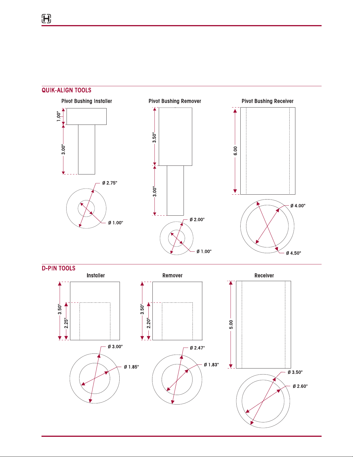
SECTION 4
Special Tools
These shop made tools are designed to install and remove pivot bushing and D-Pin bushing. Bushing tools are made from
cold rolled steel or equivalent. Drawings are for reference only. Hendrickson does not supply these tools.
17730-254 9 Special Tools
PRIMAAX® EX / PRIMAAX® for Volvo Vehicles
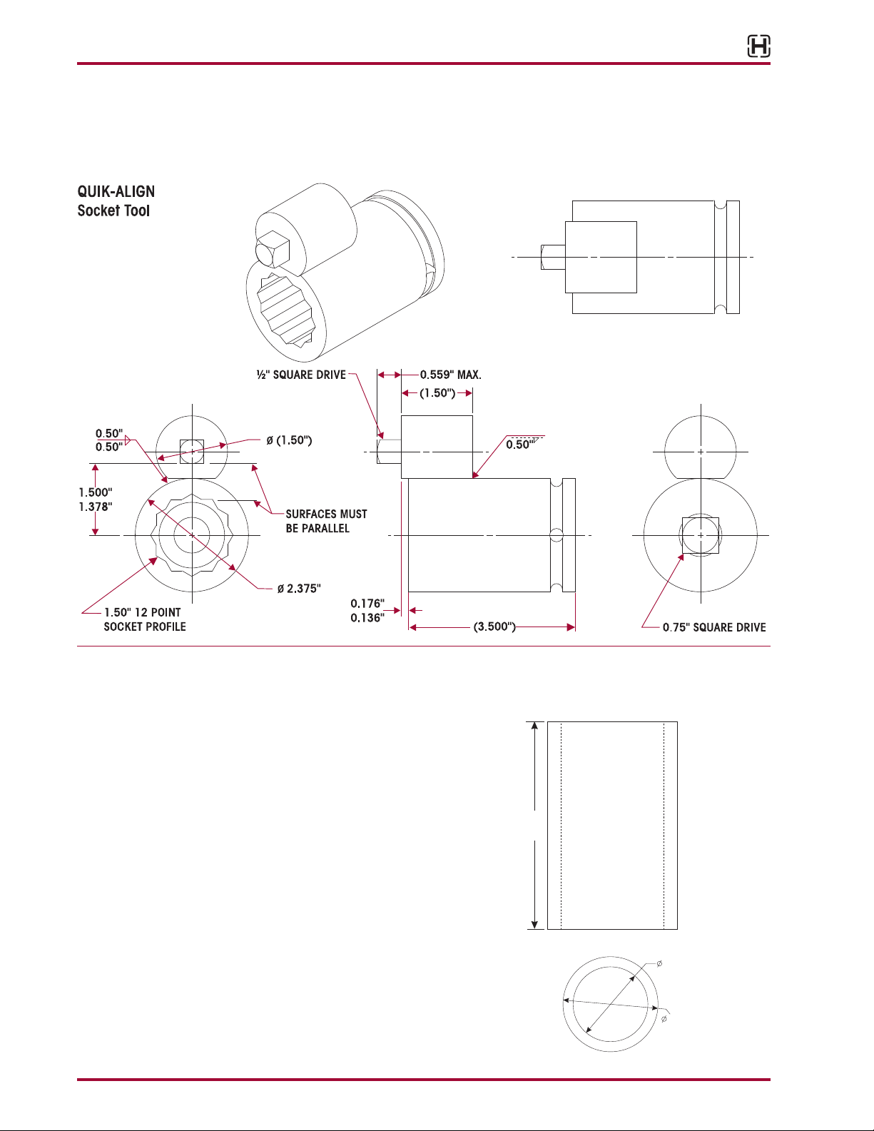
QUIK-ALIGN SOCKET TOOL
Hendrickson PRIMAAXEX QUIK-ALIGN Socket Tool is available from the Owatonna Tool Corporation (Owatonna Tool No. 1767,
website: www.otctools.com) or a shop made tool can be made from the drawing shown. Hendrickson does not supply QUIK-ALIGN
tooling. Material: Optional per customer discretion, Grade 80 or better case harden per SAE requirements.
TORQUE ROD BUSHING
This shop made tool is designed for the torque rod bushing. Bushing tools
are made from cold rolled steel or equivalent. Drawing is for reference only,
Hendrickson does not supply this tool.
TORQUE ROD
Bushing Receiver
5.00
2.00"
2.50"
Special Tools 10 17730-254
PRIMAAX® EX / PRIMAAX® for Volvo Vehicles
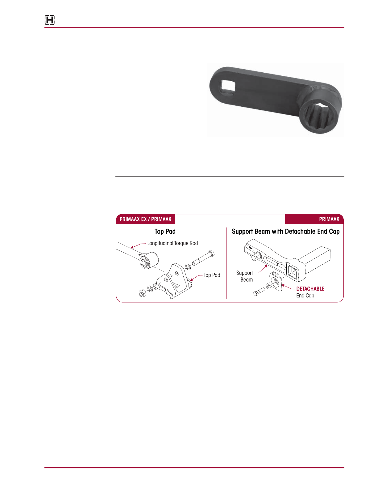
PRIMAAX EX / PRIMAAX QUICK WRENCH
FIGURE 4-1 OTC TOOL NO. 1768
Owatonna Tool Company (OTC)
manufactures a Hendrickson
approved tool (OTC Tool Number
1768) for use on PRIMAAXEX /
PRIMAAX suspensions. Contact
OTC for more information at
800-533-6127.
■
Used to tighten to torque the
longitudinal torque rod top
pad bolts and cross tube end cap bolts (if equipped).
■
Reduces maintenance time by eliminating the need to remove the tires to gain access to
the detachable end cap bolt.
NOTE Due to some vehicle configurations and/or tire sizes wheel removal may be required.
■
Use the OTC Quick Wrench tool with Hendrickson PRIMAAXEX / PRIMAAX suspension longitudinal torque rod to top pad configuration illustrated in Figure 4-2 and with PRIMAAX
suspensions detachable end cap, see Figure 4-3.
FIGURE 4-2 FIGURE 4-3
Any questions regarding the OTC Quick Wrench tooling applications contact
Hendrickson Tech Services
■
E-mail: techservices@hendrickson-intl.com
■
Telephone: 866-755-5968
17730-254 11 Special Tools
SECTION 5
Parts Lists
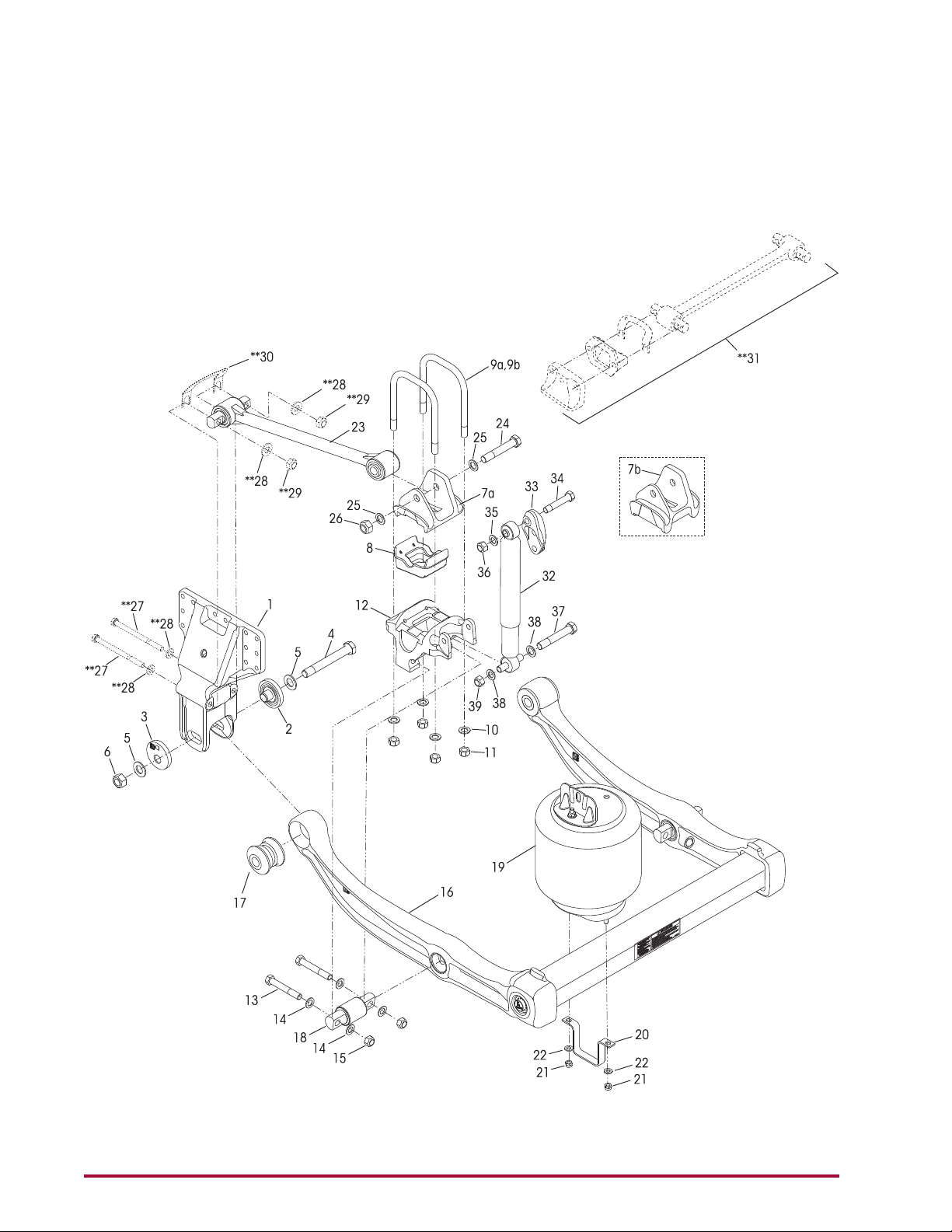
PRIMAAX EX
Parts Lists 12 17730-254
PRIMAAX® EX for Volvo Vehicles
KEY NO. PART NO. DESCRIPTION NO.REQ. KEY NO. PART NO. DESCRIPTION NO.REQ.
1 67222-000 Frame Hanger 4
60632-021 QUIK-ALIGN Collar Service Kit, Axle Set,
Includes Key Nos. 2-6
60632-020 QUIK-ALIGN Pivot Bushing Service Kit,
One Axle, Includes Key Nos. 2-6, 17
60632-019 QUIK-ALIGN Collar Service Kit,
Per Wheel End, Includes Key Nos. 2-6
60632-018 QUIK-ALIGN Fasteners Service Kit,
Per Wheel End, Includes Key Nos. 4-6
2 64633-000 QUIK-ALIGN Concentric Collar 4
3 64632-000 QUIK-ALIGN Eccentric Collar 4
4 68217-000 1.0"-14 UNF-2A H-Coat 7.5" Hex Bolt 4
5 68232-000 1.0" H-Coat Flat Washer 8
6 68218-000 1.0"-14 UNF-2B H-Coat Locknut 4
7 Top Pad 4
a 60877-001 8.5" Ride Height
b 65641-000 10" Ride Height
8 65139-003 Axle Spacer, 8.5" Ride Height (if equipped) 4
U-bolt Service Kit, One Wheel End,
48718-125 8.5" Ride Height, Includes Key Nos. 9a,10-11
48718-126 10" Ride Height, Includes Key Nos. 9b,10-11
9 U-bolt 8
a 59367-004 ¾" Square 10.375"
b 59367-009 ¾" Square 10.0"
10 22962-001 ¾" Flat Washer 16
11 49685-000 ¾"-16 UNF U-bolt Locknut 16
12 60556-XXX Bottom Cap, See pinion angle chart below 4
34013-107 D-Pin Service Kit, One Wheel End,
Includes Key Nos. 13-15, 18
13 21867-036 ¾"-16 UNF 5.0" Bolt 8
14 22962-001 ¾" Flat Washer 16
15 30191-000 ¾"-16 UNF Locknut 8
16 ***U-beam Assembly, See chart below
Includes Key Nos. 17-18
67249-003 Rear 1
67249-004 Front 1
17 58648-000 QUIK-ALIGN Pivot Bushing 4
18 60383-000 D-Pin Bushing 4
60961-230 Air Spring Assembly Service Kit,
19 67043-002 Air Spring Assembly 4
20 60911-002 Lower Air Spring Mounting Bracket 4
21 17700-010 ½"-13 UNC Locknut 8
22 22962-014 ½" Flat Washer 8
23 67274-XXX Longitudinal Torque Rod Assembly, See pinion 4
58821-012 Longitudinal Torque Rod Rear Bolt
24 30418-009
25 22962-034 7⁄8" Flat Washer 8
26 29248-000 7⁄8"-14 UNF-2B Locknut 4
27 **M16 x 2 6G Bolt 8
28 **M16 Washer 16
29 **M16 x 2 6H Locknut 8
30 **Shim (may or may not required) As req.
31 **Transverse Rod Assembly 2
60961-106 Shock Absorber Service Kit, One Wheel End,
32 60657-007 Shock Absorber 4
33 67463-006 Shock Upper Frame Bracket 4
34 50764-010 ¾"-10 UNC 4.25" Upper Shock Bolt 4
35 22962-001 ¾" Flat Washer 4
36 49842-000 ¾"-10 UNC Locknut 4
37 32043-017 5⁄8"-11 UNC 6.0" Lower Shock Bolt 4
38 22962-004 5⁄8" Flat Washer 8
39 47764-000 5⁄8"-11 UNC-2B Locknut 4
Not Shown **Height Control Valve Assembly 1
Not Shown **Height Control Valve Linkage 1
One Wheel End, Includes Key Nos. 19-22
angle chart below, Replaces 64981-XXX
Service Kit, One Side Only,
Includes Key Nos. 24-26
7
⁄8"-14 UNF-2A 5.5" Hex Bolt 4
Includes Key Nos. 32, 34-39
NOTE: * Quantities shown are for a tandem con guration.
** Item Required, component supplied by vehicle manufacturer. Hendrickson is not responsible for components not supplied by Hendrickson, for
assistance with maintenance and rebuild instructions on these components see vehicle manufacturer.
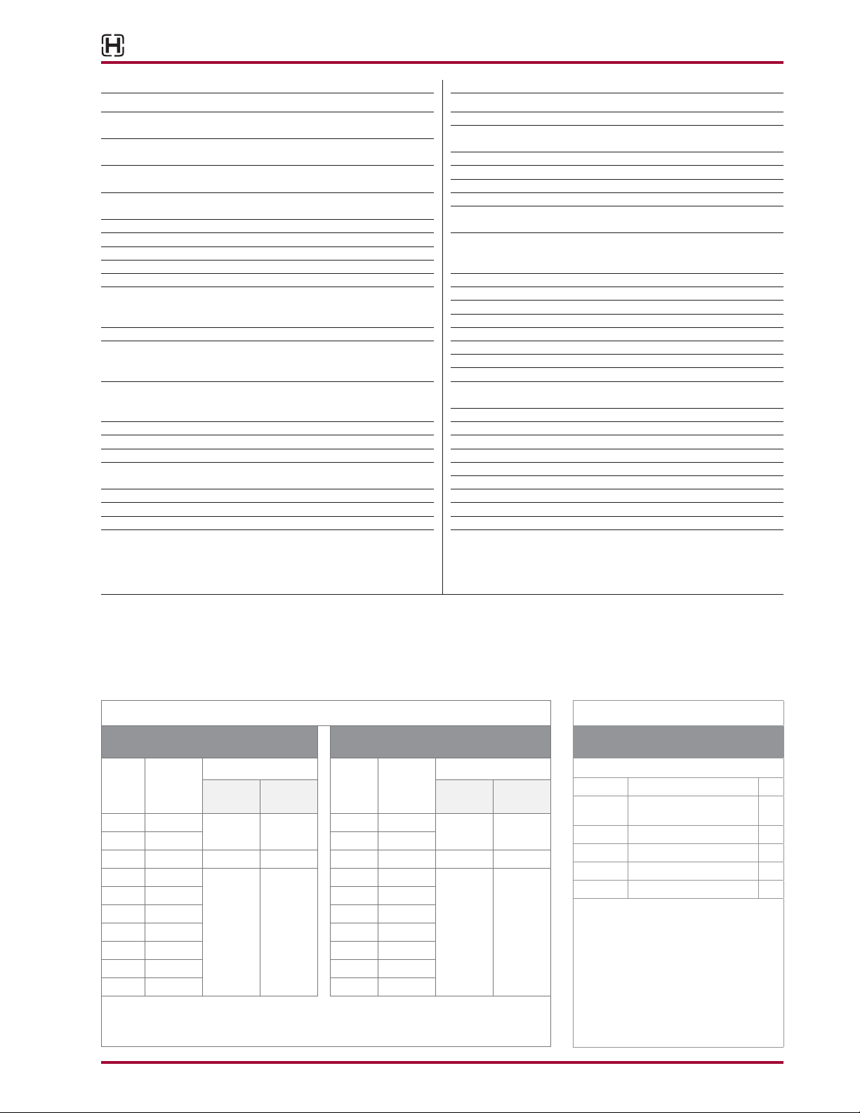
Pinion Angle Chart
8.5'' RIDE HEIGHT 10'' RIDE HEIGHT
Pinion
Bottom Cap
Angle
(degree)
10.3 60556-100
10.7 60556-105 10.2 60556-105
11.2 60556-110 10.7 60556-110
11.6 60556-115 11.2 60556-115
12.1 60556-120 11.6 60556-120
13.4 60556-135 13.1 60556-135
Measured with Pinion QUIK-ALIGN at neutral position (12 O'Clock)
Part No.
2.9 60556-025
6 60556-060 6.1 60556-060
7.9 60556-120 550 (front) 67274-550 8.2 60556-120 550 (front) 67274-550
13 60556-130 12.6 60556-130
Longitudinal Torque Rod
Length
(mm)
530 (front) 67274-530
575 (rear) 67274-575
Part No
Pinion
Bottom Cap
Angle
(degree)
2.9 60556-025
9.8 60556-100
Part No.
Longitudinal Torque Rod
Length
(mm)
530 (front) 67274-530
570 (rear) 67274-570
Part No
***U-beam Assembly Enhancement
AFTERMARKET SERVICE KIT
NO. 69565-001, AXLE SET
CONTENTS
PART NO. DESCRIPTION QTY.
69351-000
69432-000 Tamper Resistant Cap 2
69570-000 Loctite® 277 - 10 ml Bottle 1
50104-0067⁄8"-9 UNC 4.0" Hex Bolt 2
22962-0427⁄8" H-Coat Flat Washer 2
*** In the event any service to the suspension
Sika ex 221 Polyurethane
Sealant, 300 ml Tube
requiring disassembly of a U-beam
assembly equipped with integrated end
caps, the Loctite 277, tamper resistant caps
and Sika ex 221 polyurethane sealant
must be properly installed to ensure
components function to their highest
ef ciency. The enhancement components
can be purchased individually or as an
aftermarket service kit.
1
17730-254 13 Parts Lists
PRIMAAX® for Volvo Vehicles
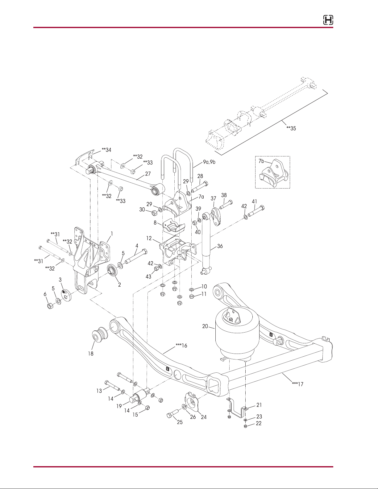
PRIMAAX
Parts Lists 14 17730-254
PRIMAAX® for Volvo Vehicles
KEY NO. PART NO. DESCRIPTION NO.REQ. KEY NO. PART NO. DESCRIPTION NO.REQ.
1 65702-001 Frame Hanger 4
60632-021 QUIK-ALIGN Collar Service Kit, Axle Set,
Includes Key Nos. 2-6
60632-020 QUIK-ALIGN Pivot Bushing Service Kit,
One Axle, Includes Key Nos. 2-6, 18
60632-019 QUIK-ALIGN Collar Service Kit,
Per Wheel End, Includes Key Nos. 2-6
60632-018 QUIK-ALIGN Fasteners Service Kit,
Per Wheel End, Includes Key Nos. 4-6
2 64633-000 QUIK-ALIGN Concentric Collar 4
3 64632-000 QUIK-ALIGN Eccentric Collar 4
4 68217-000 1.0"-14 UNF-2A H-Coat 7.5" Hex Bolt 4
Replaces 64107-000
5 68232-000 1.0" H-Coat Flat Washer 8
Replaces 22962-035
6 68218-000 1.0"-14 UNF-2B H-Coat Locknut 4
Replaces 64108-000
7 Top Pad 4
a 60877-001 8.5" Ride Height
b 65641-000 10" Ride Height
8 65139-003 Axle Spacer, 8.5" Ride Height (if equipped) 4
U-bolt Service Kit, One Wheel End,
48718-125 8.5" Ride Height, Includes Key Nos. 9a,10-11
48718-126 10" Ride Height, Includes Key Nos. 9b,10-11
9 U-bolt 8
a 59367-004 ¾" Square 10.375"
b 59367-009 ¾" Square 10.0"
10 22962-001 ¾" Flat Washer 16
11 49685-000 ¾"-16 UNF U-bolt Locknut 16
12 60556-XXX Bottom Cap, See pinion angle chart on page 3 4
34013-107 D-Pin Service Kit, One Wheel End,
Includes Key Nos. 13-15, 19
13 21867-036 ¾"-16 UNF 5.0" Bolt 8
14 22962-001 ¾" Flat Washer 16
15 30191-000 ¾"-16 UNF Locknut 8
16 ***Support Beam Assembly (60831-XXX, see
replacement guide below)
17 ***Cross Tube (60912-001, see replacement
guide below)
18 58648-000 QUIK-ALIGN Pivot Bushing 4
19 60383-000 D-Pin Bushing 4
60961-062 Air Spring Assembly Service Kit,
One Wheel End, Includes Key Nos. 20-23
20 60271-002 Air Spring Assembly 4
21 60911-000 Lower Air Spring Mounting Bracket 4
22 17700-010 ½"-13 UNC Locknut 8
23 22962-014 ½" Flat Washer 8
24 60822-000 End Cap 4
25 50104-003
7
⁄8"-9 UNC 3.5" Hex Bolt 4
26 22962-034 7⁄8" Dacromet Flat Washer 4
27 67274-XXX Longitudinal Torque Rod Assembly, See pinion 4
angle chart on page 3, Replaces 64981-XXX
58821-012 Longitudinal Torque Rod Rear Bolt
Service Kit, One Wheel End,
Includes Key Nos. 28-30
28 30418-009 7⁄8"-14 UNF-2A 5.50" Hex Bolt 4
29 22962-034 7⁄8" Dacromet Flat Washer 8
30 29248-000 7⁄8"-14 UNF-2B Locknut 4
31 **M16 x 2 6G Bolt 8
32 **M16 Washer 16
33 **M16 x 2 6H Locknut 8
34 **Shim (may or may not be required) As Req
35 **Transverse Rod Assembly 2
60961-106 Shock Absorber Service Kit, One Wheel End,
Includes Key Nos. 36, 38-43
36 60657-007 Shock Absorber 4
37 67463-006 Shock Upper Frame Bracket 4
Replaces 65000-006
38 50764-010 ¾"-10 UNC 4.25" Upper Shock Bolt 4
39 22962-001 ¾" Flat Washer 4
40 49842-000 ¾"-10 UNC Locknut 4
41 32043-017 5⁄8"-11 UNC 6.0" Lower Shock Bolt 4
42 22962-004 5⁄8" Flat Washer 8
43 47764-000 5⁄8"-11 UNC-2B Locknut 4
Not Shown **Height Control Valve Assembly 1
Not Shown **Height Control Valve Linkage 1
NOTE: * Quantities shown are for a tandem con guration.
** Item Required, component supplied by Vehicle Manufacturer. Hendrickson is not responsible for components not supplied by Hendrickson, for
assistance with maintenance and rebuild instructions on these components see vehicle manufacturer.
*** No longer available for service, see replacement guide below. For more information, refer to Hendrickson Technical Bulletin SEU-0229 or contact
Hendrickson Tech Services.
SUPPORT BEAM AND CROSS TUBE ASSEMBLY REPLACEMENT GUIDE
Key No. Description Current Part No. Replacement Kit No. Comments
60831-003 (LHF)
16 Support Beam Assembly
60831-004 (RHF)
60831-001 (LHR)
60831-002 (RHR)
17 Cross Tube 60912-001
17730-254 15 Parts Lists
60961-237 (Forward)
60961-238 (Rear)
60961-237 (Forward)
60961-238 (Rear)
Requires the replacement of associated suspension parts on one axle.
Replacement Kit includes two new support
beam assemblies, one cross tube, two air
spring assemblies, air spring fasteners,
QUIK-ALIGN fasteners and D-pin fasteners.

PRIMAAX® EX / PRIMAAX® for Volvo Vehicles
SECTION 6
Preventive Maintenance
Following appropriate inspection procedures is important to help ensure the proper maintenance
and operation of the suspension system and component parts. Hendrickson recommends the
PRIMAAX® EX • PRIMAAX® heavy-duty rear suspension is inspected at pre-delivery, the first 1,000
miles of service and at the regular preventive maintenance intervals. Off-highway and severe service operating conditions require more frequent inspections than on-highway service operation.
Following appropriate inspection procedures is important to help ensure the proper maintenance and operation of the PRIMAAXEX • PRIMAAX suspension system and component parts
function to their highest efficiency.
NOTE Torque values shown in this publication apply only if Hendrickson supplied fasteners are used.
If non Hendrickson fasteners are used, follow the torque specification listed in the vehicle
manufacturer’s service manual.
AREAS OF INSPECTION
The inspection must include the following components:
➤ Air springs
• Air supply and fittings
• All fasteners
• Tire wear
➤ Clamp group
➤ Top pad
➤ U-bolt locknuts
➤ U-beam assembly
• Cross tube
• Support beam
• End cap (enhanced or
detachable)
• Frame hanger bracket
• Height control valve
➤ QUIK-ALIGN® connections
• S-cam support tube
bracket
• Shock absorbers
• Torque rods
– Transverse
– Longitudinal
➤ Signifies performance critical components.
HENDRICKSON RECOMMENDED
PREVENTIVE MAINTENANCE INTERVALS
PRE-DELIVERY INSPECTION
1. Visually inspect the suspension for proper assembly.
2. Verify the lateral alignment of the drive axles are within the vehicle manufacturer’s tolerances, contact the vehicle manufacturer for the correct lateral alignment instructions.
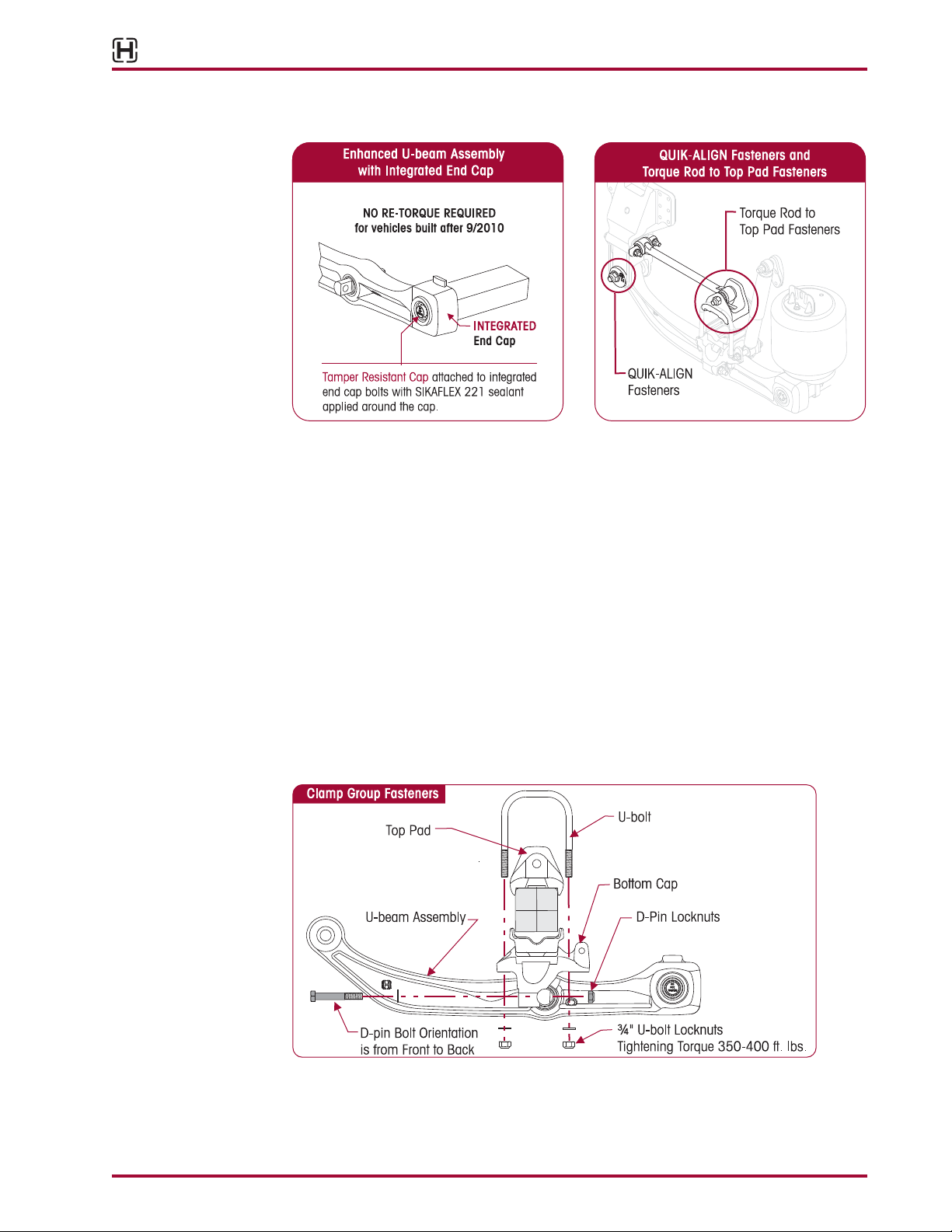
3. Visually inspect the overall condition of the U-beam assembly (support beam assembly,
cross tube, and integrated end cap) for any damage.
4. DO NOT RE-TORQUE the integrated end cap (vehicles built AFTER April 2011), see Figure
6-1.
5. Check all other fasteners for proper torque with special attention to the following suspension connections:
■
QUIK-ALIGN fasteners, see Figure 6-2.
■
Torque rod to top pad fasteners, see Figure 6-2.
■
Clamp group fasteners (U-bolts), see Figure 6-3.
6. Verify the ride height is within specification. Ride height is measured from the bottom of the
frame rail to the centerline of the axle.
Preventive Maintenance 16 17730-254
PRIMAAX® EX / PRIMAAX® for Volvo Vehicles
FIGURE 6-1 FIGURE 6-2
INSPECTION AT 1,000 MILES
1. Visually inspect suspension components with special attention to air springs and U-beam
assembly (support beam assembly, cross tube, and integrated end cap). Check for:
■
Proper suspension function
■
Any signs of unusual movement, loose or missing components
■
Any signs of abrasive or adverse contact with other components
■
Any damaged, bent or cracked parts
2. Check all fasteners for proper torque with special attention to the following suspension
connections.
■
QUIK-ALIGN fasteners, see Figure 6-2.
■
Torque rod to top pad fasteners, see Figure 6-2.
■
Clamp group fasteners (U-bolts), see Figure 6-3.
FIGURE 6-3
17730-254 17 Preventive Maintenance
PRIMAAX® EX / PRIMAAX® for Volvo Vehicles
PREVENTIVE MAINTENANCE – PRIMAAX EX • PRIMAAX
■
Off highway and severe service – Every 25,000 miles or six months, whichever comes first
■
100% On-highway – Every 50,000 miles or 12 months, whichever comes first
1. Visually inspect suspension components with special attention to air springs and U-beam
Assembly (support beam assembly, cross tube, and integrated or detachable end cap).
Check for:
■
Proper suspension function
■
Any signs of unusual movement, loose or missing components
■
Any signs of abrasive or adverse contact with other components
■
Any damaged, bent or cracked parts
2. Check all fasteners for proper torque with special attention to the following suspension
connections.
■
QUIK-ALIGN fasteners, see Figure 6-2.
■
Torque rod to top pad fasteners, see Figure 6-2.
■
Clamp group fasteners (U-bolts), see Figure 6-3.
FIGURE 6-4
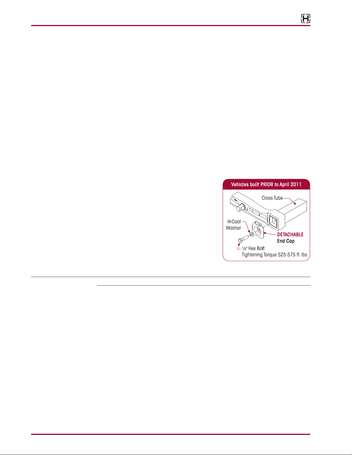
■
Check detachable end cap connection fasteners on PRIMAAX vehicles (built PRIOR to
April 2011), see Figure 6-4.
3. Verify the ride height is within specification.
Ride height is measured from the bottom of the
frame rail to the centerline of the axle.
4. Verify that the lateral alignment of the drive axle
is within the vehicle manufacturer’s tolerances,
contact the vehicle manufacturer for the correct
lateral alignment instructions.
COMPONENT INSPECTION
IMPORTANT NOTE Replace all worn or damaged parts.
■
Air spring — Visually inspect the outer surface of the air spring for chafing, uneven wear,
cracks or any signs of component damage. Ensure that the upper bead plate is tight against
the underside of the frame. Check for any lateral slippage at the lower air spring bracket.
An 1⁄8" of slippage in either direction is acceptable. Verify all mounting hardware have the
proper torque values maintained. See Torque Specification Section of this publication for
recommended torque requirements.
■
Air supply (Pneumatic components) — The air supply to the system plays a large role in
the air springs’ performance. Inspect, clean and replace, if necessary, any support products
to the air springs, valves, regulators and air lines. See Air Fitting Inspection in this section if
an air leak is suspected.
■
Clamp group — Visually inspect for any loose or damaged fasteners. Verify the U-bolt
locknuts have the proper torque values maintained. See the U-bolt Locknuts in this section.
■
End cap (if equipped) — Visually inspect the end cap connection for signs of movement
or damage. Verify the support beam / cross tube connection bolts have the proper torque
values maintained. See Torque Specification Section of this publication for recommended
torque requirements.
Preventive Maintenance 18 17730-254
 Loading...