

HENDRICKSON MAXX22T Installation Manual
Technical
Procedure
TRAILER SUSPENSION SYSTEMS
AIR DISC BRAKE (ADB)
SUBJECT: Hub and Rotor Assembly
Caliper Mounting Procedures
LIT NO: T71004
DATE: September 2023 REVISION: G
ROTOR TO HUB ASSEMBLY
Not all hub and rotor assemblies are the same. Refer to
the applicable procedure listed in this section.
NOTE: The hub and rotor assembly must be installed
before mounting the ADB caliper.
NOTICE: Thoroughly inspect rotor condition
before reuse. For details, refer to
T72009
Maintenance
IMPORTANT: Hendrickson does not recommend
reusing fasteners.
CAUTION: DO NOT lift an ADB caliper assembly
by the brake pad retainer bracket.
Other relative literature may include:
LIT NO. DESCRIPTION
T12007 General Safety Precautions & Information for
Technical Procedures
T72009 MAXX22T Installation & Maintenance Procedures
T82006 Recommended Stud Replacement Procedures
TOOLS REQUIRED
The following tools may be required during the
performance of some maintenance procedures:
TOOL WHERE USED TORQUE
Torque Wrench 10
to 250 ft-Ib
15/16 inch socket Outboard Mounted Rotor 5/8 inch
24mm socket or
15/16 inch socket
13mm socket Bendix Splined Disc Rotor
15/16 inch socket ConMet Flat Rotor and Hub
MAXX22T™ Installation &
or rotor manufacturer.
Used with sockets listed in this
table
ange nuts Figure 1
Flanged Mounted Hub and
U-Shaped Rotor M16mm screws
or 5/8 inch screws Figure 3
Assembly M8mm screws Figure 5
Assembly 5/8 inch ange nuts
Figure 6
Table 1: Tools Required
N/A
220 ft-Ib
220 ft-Ib
22 ft-Ib
200 ft-Ib
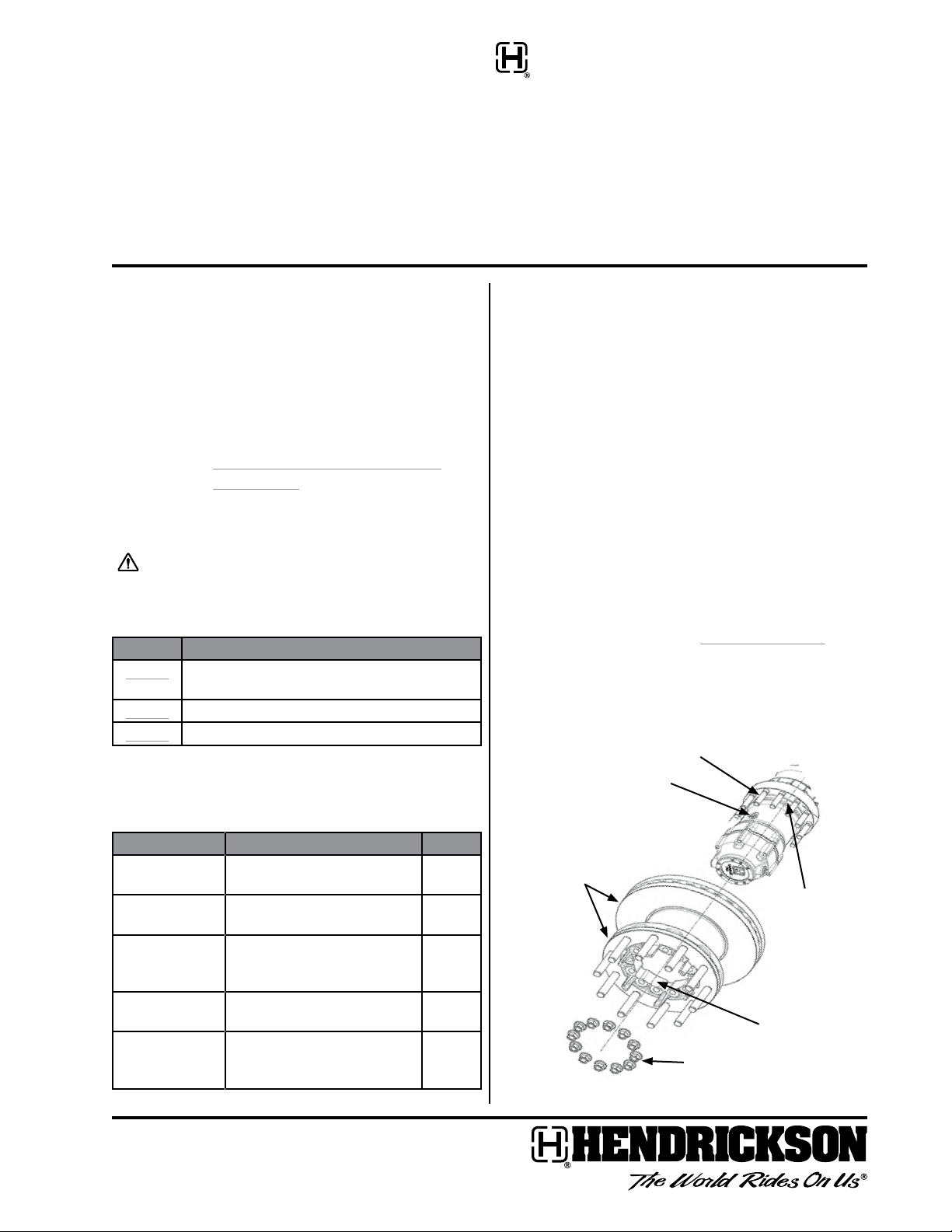
OUTBOARD MOUNTED ROTOR
1. Ensure both hub and rotor mounting surfaces are
free of loose dirt, corrosion, grease, and debris.
NOTE: Applying a light lm of lube to the rotor ange
ID may help ease sliding the rotor ange ID
over the hub rotor pilot.
2. With hub mounted on the axle, slide the new rotor
assembly onto the hub until the rotor ange ID
engages the hub rotor pilot (Figure 1).
NOTE: Ensure the hub ll port (Figure 1) is not directly
under a wheel stud.
3. Install the 12 ange nuts and hand tighten.
4. Once all the nuts are hand tightened, properly
constrain assembly and tighten the ange nuts,
in the sequence shown in Figure 2 on page 2, to
220±10 ft. Ibs. (300±10Nm) of torque.
IMPORTANT: DO NOT APPLY anti-seize compound or
additional lubricant to fastener threads.
Wheel studs (x12)
Hub Fill port
Rotor
assembly
Hub rotor
pilot
Rotor ange ID
Figure 1: Outboard Mounted Rotor
HUB AND ROTOR ASSEMBLY CALIPER MOUNTING PROCEDURES
1
4
10
9
2
1
12
8
4
10
6
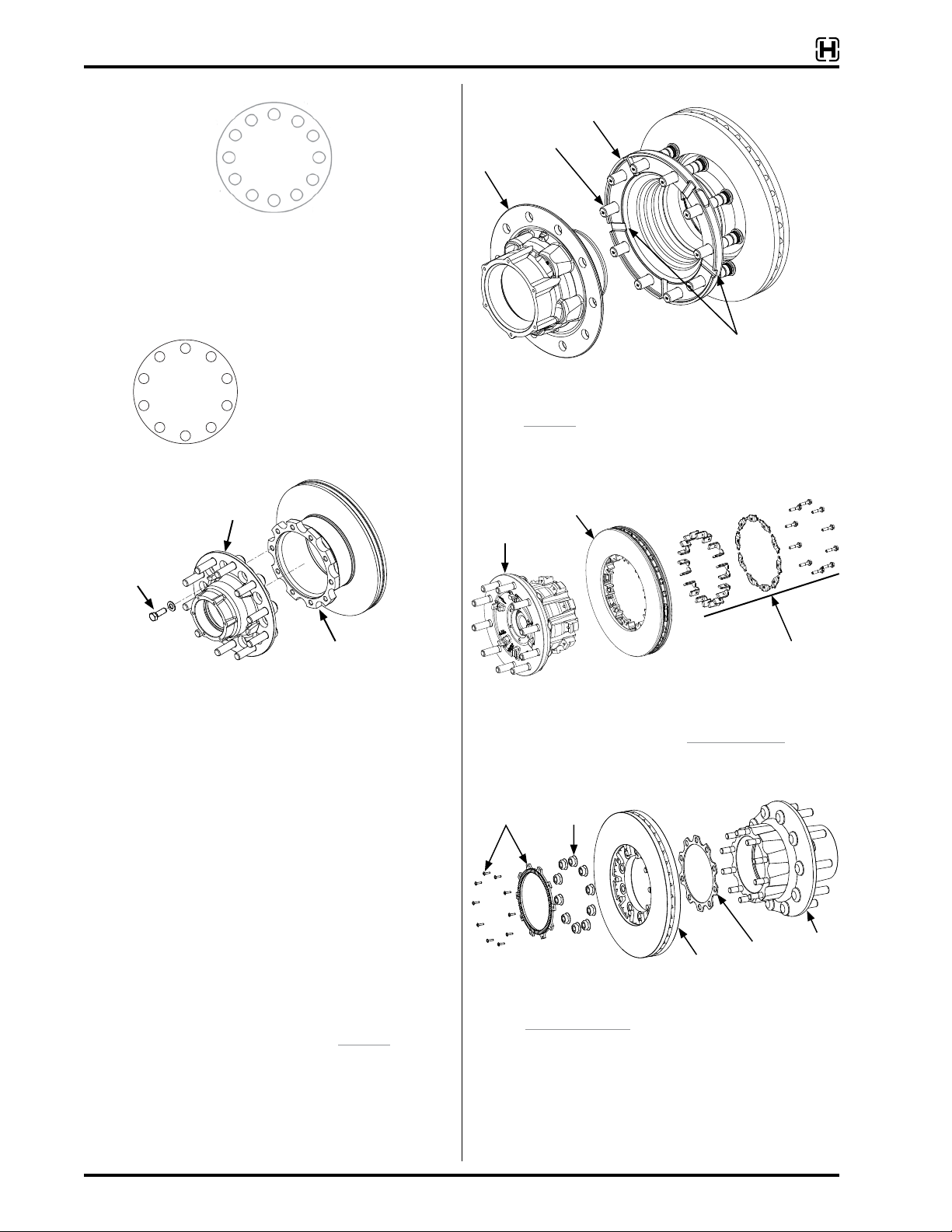
Figure 2: Outboard Mounted Rotor torque sequence
5
9
3
7
11
2
FLANGED MOUNTED HUB AND U-SHAPED
ROTOR
6
M16 or 5/8”-11
Mounting
screws x10
7
3
Rotor torque sequence
for all U-shaped rotors
58
Hub
STUD MOUNTED ROTOR
U-shaped rotor
Studs (x10)
Hub
Drain slots (x5)
Figure 4: Hendrickson stud mounted hub & U-shaped rotor assembly
Refer to T82006 for disassembly or stud replacement
procedures.
BENDIX SPLINED DISC® ROTOR ASSEMBLY
Splined Disc
Splined hub
®
rotor
Rotor
Figure 3: Flange mounted hub & U-shaped rotor assembly
Figure 5: ConMet hub & Bendix Splined Disc rotor assembly
Splined Disc
rotor hardware
1. Ensure both hub and rotor mounting surfaces are
clean and free of loose dirt, corrosion, grease, and
For rotor information, refer to the Bendix website.
debris.
2. Place the rotor onto a stable work surface with
the outboard mounting surface facing upward.
CONMET FLAT ROTOR AND HUB ASSEMBLY
Tone ring &
10 fasteners
Flanged
nuts (x10)
3. Carefully lower the hub onto the rotor until the
hub mounting pilot engages the rotor bore.
IMPORTANT: DO NOT APPLY anti-seize compound or
additional lubricant to fastener threads.
4. Align fastener holes and insert new screws and
washers.
5. Hand tighten.
6. Properly constrain assembly and tighten mounting
Figure 6: ConMet hub & at rotor assembly
Refer to ConMet website.
Flat rotor
Insulator
Hub
screws, in the sequence shown in Figure 3, to
220±10 ft. lbs. (300±10 Nm) of torque.
NOTE: Ensure the heads of the new screws are
recessed below the ange wheel mounting
surface.
2
T71004 G
 Loading...