

Page 1
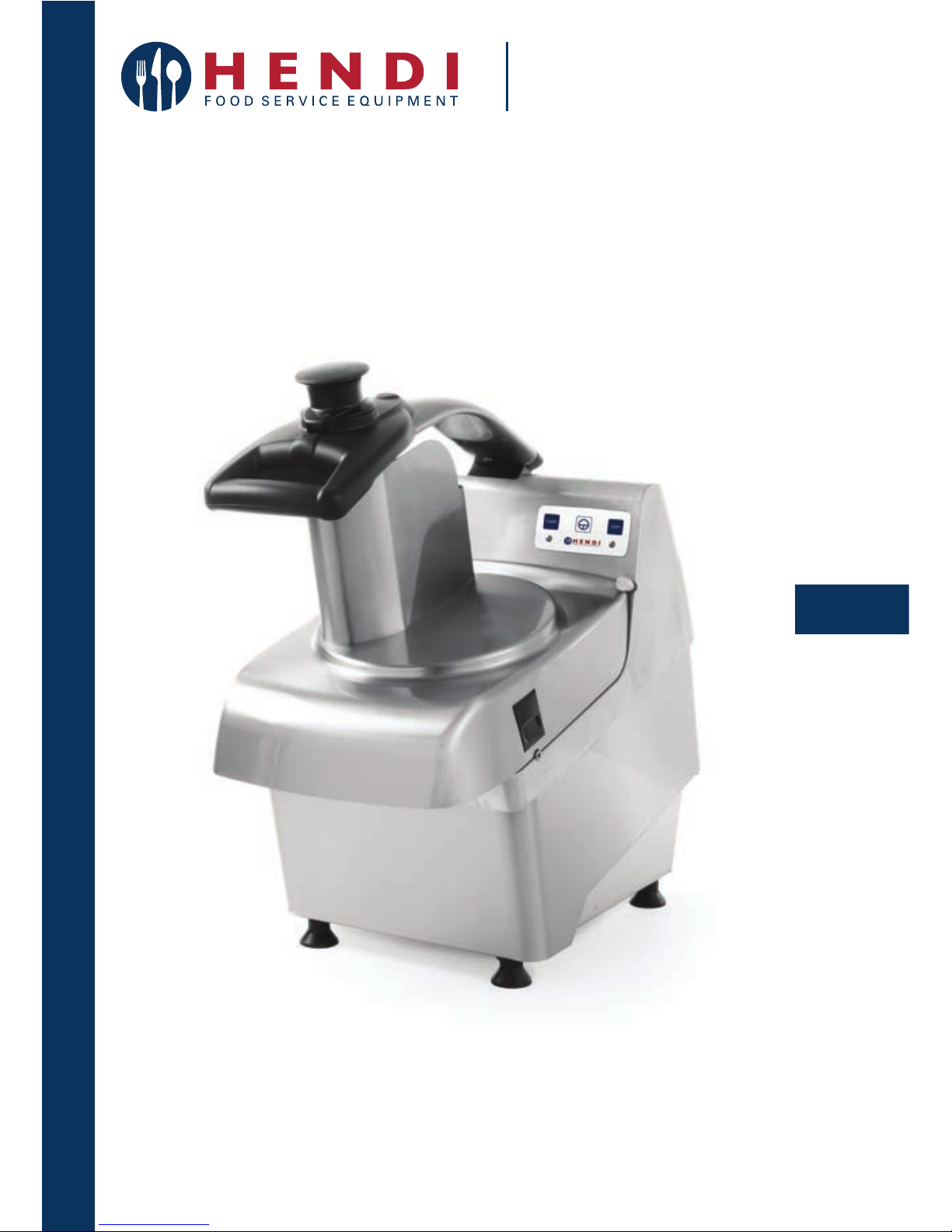
User instructions
Gebrauchsanweisung
Gebruiksaanwijzing
Instrukcja obsługi
Mode d’emploi
Istruzioni per l’uso
Instrucţiunile utilizatorului
You should read these user instructions carefully before
using the appliance
Bevor Sie das Gerät in Betrieb nehmen, sollten Sie
diese Gebrauchsanweisung aufmerksam lesen
Alvorens de apparatuur in gebruik te nemen dient
u deze gebruiksaanwijzing aandachtig te lezen
Przed uruchomieniem urządzenia należy koniecznie
dokładnie przeczytać niniejszą instrukcję obsługi
Lisez attentivement ce mode d’emploi avant d’utiliser
l’appareil
Citiți cu atenție prezentul manual de utilizare înainte
de folosirea aparatului
VEGETABLE CUTTER MACHINE
SZATKOWNICA ELEKTRYCZNA
231845
Page 2

EN
2
INDEX
CAP. 1. CONTENT ORGANIZATION AND CONSULTATION MODALITY ........... 3
CAP. 2. GENERAL INFORMATION AND CHARACTERISTICS ......................... 4
CAP. 3. SAFETY INSTRUCTIONS .................................................................... 7
CAP. 4. TRANSPORTATION, PUT ON SERVICE AND USE .............................. 9
CAP. 5. MAINTENANCE, DAMAGES RESEARCH AND CLEANING .............. 14
CAP. 6. SELLING .......................................................................................... 18
CAP. 7. MANUFACTURING MATERIALS ....................................................... 19
Page 3

EN
3
CHAP. 1. CONTENT ORGANIZATION AND CONSULTATION MODALITY
MANUAL PURPOSE
MANUAL IMPORTANCE
The present instruction manual for the use is to be considered as integral part of the machine:
• Must be kept for all the machine life.
• Must be coupled with the machine in case of its
ceasing.
• Besides to show all useful notices for the opera-
tors, contains (collected in specific chapters) the
electric diagrams that will be used for the possible maintenance interventions and reparation.
SCOPE / MANUAL PURPOSE
The instructions manual for the use has the purpose
to furnish to the commitment all necessary information so that, except of an adequate supplied machine
use, is able to manage the same in the more autonomous way and possibly safe.
Besides the present manual has been written with
the purpose to supply indications and warnings to
know the supplied machine, to understand its principles and functioning limits. For possible doubts you
can call the Authorized Assistance Center.
RECEIVERS
The present instruction manual for the use, delivered in number of 1 copy together with the machine,
is supplied as integral part of the machine, is turned
both to the operators both to the skilled technicians
qualified to the installation, use and maintenance.
The prevention and protection service responsible
of the commitment and the additional employers, to
whom is assigned the machine, must take vision of
the present instructions manual for the use, with the
aim to adopt all technical and organizational measures.
RESPONSIBILITY
• If the present manual endures damages or is lost,
it is possible to request a copy to the Authorized
Assistance Center.
• The present manual reflects the technical state
during the machine manufacturing; the manufacturer reserves the right to update the production
and of consequence other manual issues, without
the obligation to update productions or previous
manuals, if not in particular cases regarding the
health and the people safety.
• Pay particularly attention to the residual risks
content present on the machine and the prescriptions to which the operators must keep.
• The manufacturer is the responsible for the machine in its original configuration.
• The manufacturer isn’t the responsible for damages caused from the improper use or not correct
of the machine and documentation or for damages
caused from the imperative standards violation,
negligence, lack of experience, imprudence and
the not respect of regulation standards on behalf
of the employer, of the operator or the maintenanc
e
man and for every possible damage, caused from
an irrational, improper and/or wrong use.
• The manufacturer isn’t the responsible for the
consequences caused from the not original spare
parts use or of equal characteristics.
• The manufacturer is the responsible only for the
information showed in the manual original version
in Italian language.
• The non-fulfillment prescriptions contained in
this manual will cause the guarantee immediate
decay.
The factory responsible, that supervision to the working activities, in the field of the foreseen respective
attributions and competence, must:
• Carry out the foreseen safety measures;
• Make informed the operators about the specific
risks whom are exposed and bring to their know-
ledge the prevention essential standards;
• Prepare and require that the single operators observe the safety standards and use the protection
means put at their disposal;
• Get down to work more operators, contemporary,
on this product.
Page 4
EN
4
SIMBOLOGY MEANING
Here follow it is clearly specified the symbols and definitions meaning, which will be used in the present
document.
DANGER
It shows the danger presence for who works on the machine and for who is in the vicinity, so
the indicated activity must be performed in accordance with the actual accident prevention
standards and with the indications showed in the present manual.
PRECAUTION
It shows a warning on useful information and/or further recommendations and/or shrewdness about the actual operation.
ATTENTION
It shows an operation to perform with attention to avoid damage to the machine.
CHAP. 2. GENERAL INFORMATION AND CHARACTERISTICS
The vegetables processor here follow called “machine”, is designed to slice, to cube and to grate fruit, fresh
vegetables of all known types (courgettes, carrots, celery, tomatoes, etc…) and others of same solidity.
The machine is constituted from an electric motor
inserted in a unique fusion (base machine body), in
which the motor shaft is connected to the cutting
tool through proper transmission belts.
The food product, loaded manually, can be placed:
1. within the loading mouth to cube or to unravel or
to spline, placed in the machine left superior zone
and always manually, pushing the pressure th-
rough its handle, the product is driven against the
cutting zone. The product loading must happen in
moderate quantity to avoid that lowing the pressure the machine doesn’t start, due to the safety micro switch placed in the pressure block;
2. within the loading mouth to cut, placed in the ma-
chine right superior zone and always manually
and with the help of the pestle is introduced in the
machine neck towards the cutting zone. The
pestle is of plastic material suitable for the con-
tact with food products.
The loading mouth to cube and the loading mouth to
cut are placed on the closure cover blocked to the
machine through a proper knob: on the machine is
placed a safety micro switch that points out the cover right position.
The machine cutting zone includes its internal zone
where some rotating discs can be placed manually
supplied of bayonet joint with the motor shaft and
other fixed discs:
1. rotating discs to slice and grate;
2. rotating discs to slice;
3. rotating discs to slice with matches form;
4. fixed discs to cube;
5. fixed discs for spline cutting;
6. rotating expeller disc.
In the machine front inferior zone the unloading
mouth is present where exiles the cut food product.
All direct contact materials with the food product
are in conformance with the actual hygienic standards for foods.
In accordance with the functioning and production
requirements, the machine can be constituted with
different optional parts.
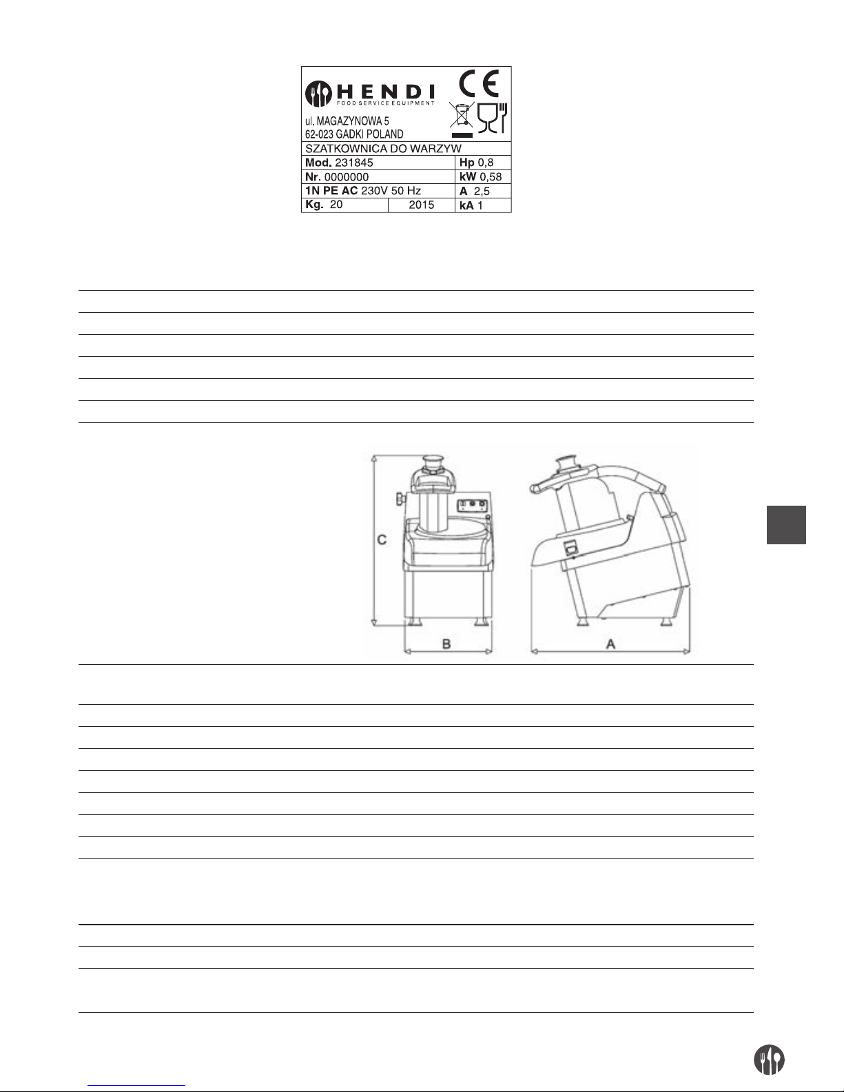
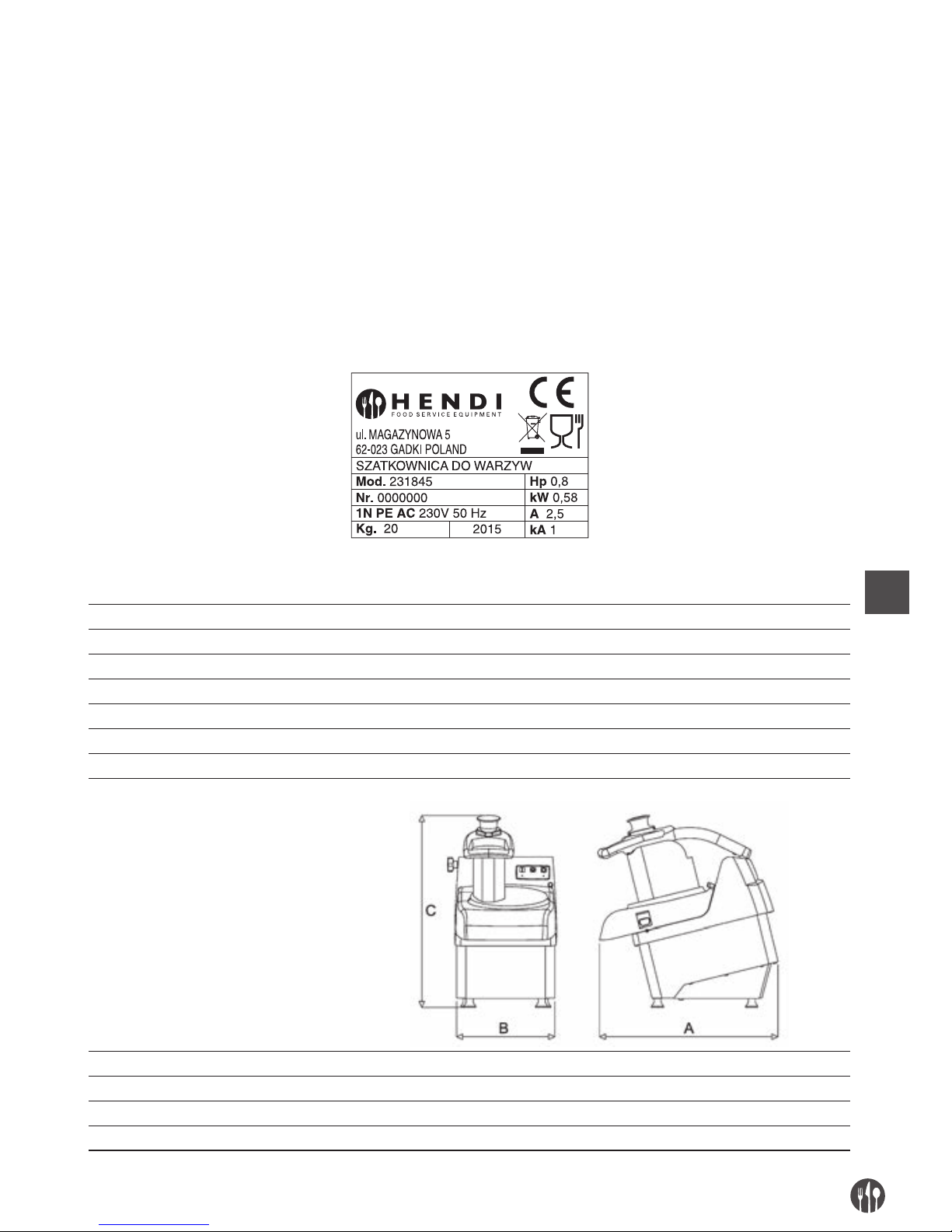
The machine is supplied with an identification plate
on which the following data are showed:
Page 5
EN
5
TECHNICAL AND MANUFACTURING DATA
Motor power (kW) / (Hp) 0,58kW / 0,80Hp
Loading mouth internal size to cube (mm) 180 x 80
Loading mouth neck length to cube (mm) 150
Loading mouth internal size to cut (mm) 57
Loading mouth neck height to cut (mm) 190
Timetable production (kg/h) 250-450
Mass (kg) 21,5
Sizes: A x B x C (mm) 490 x 280 x 530
Acoustic power level continue
equivalent considered A
Minor of 70dBA
Current nature – Frequency Cfr. Machine plate
Full charge current Cfr. Machine plate
Use nominal voltage Cfr. Machine plate
Auxiliary circuits voltage AC 24V – DC 24V
Mass and neutral TT e TN
Protection degree IP X3
Use place Inside
Umiejscowienie urządzenia Work bench used in the food sector of height included between 900/1100mm
from the trampling plane of adequate capacity, with a circulation
free space of at least 800mm
Max environment air temperature +40°C
Requested minimum illumination 500 lux
Product directives conformances 2006/42/CE, 2006/95/CE and successive modifications and integration,
Reg. 1935/2004
Page 6
EN
6
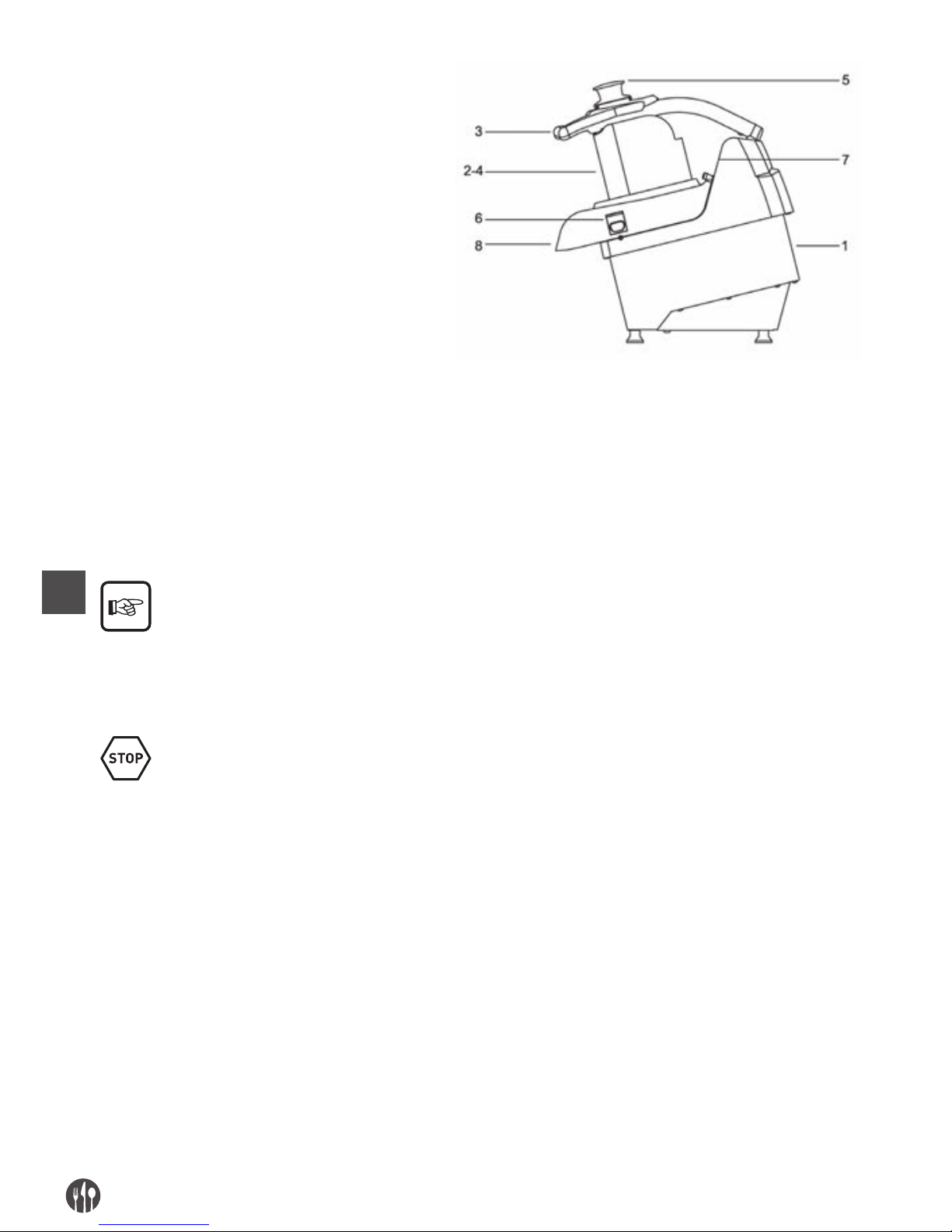
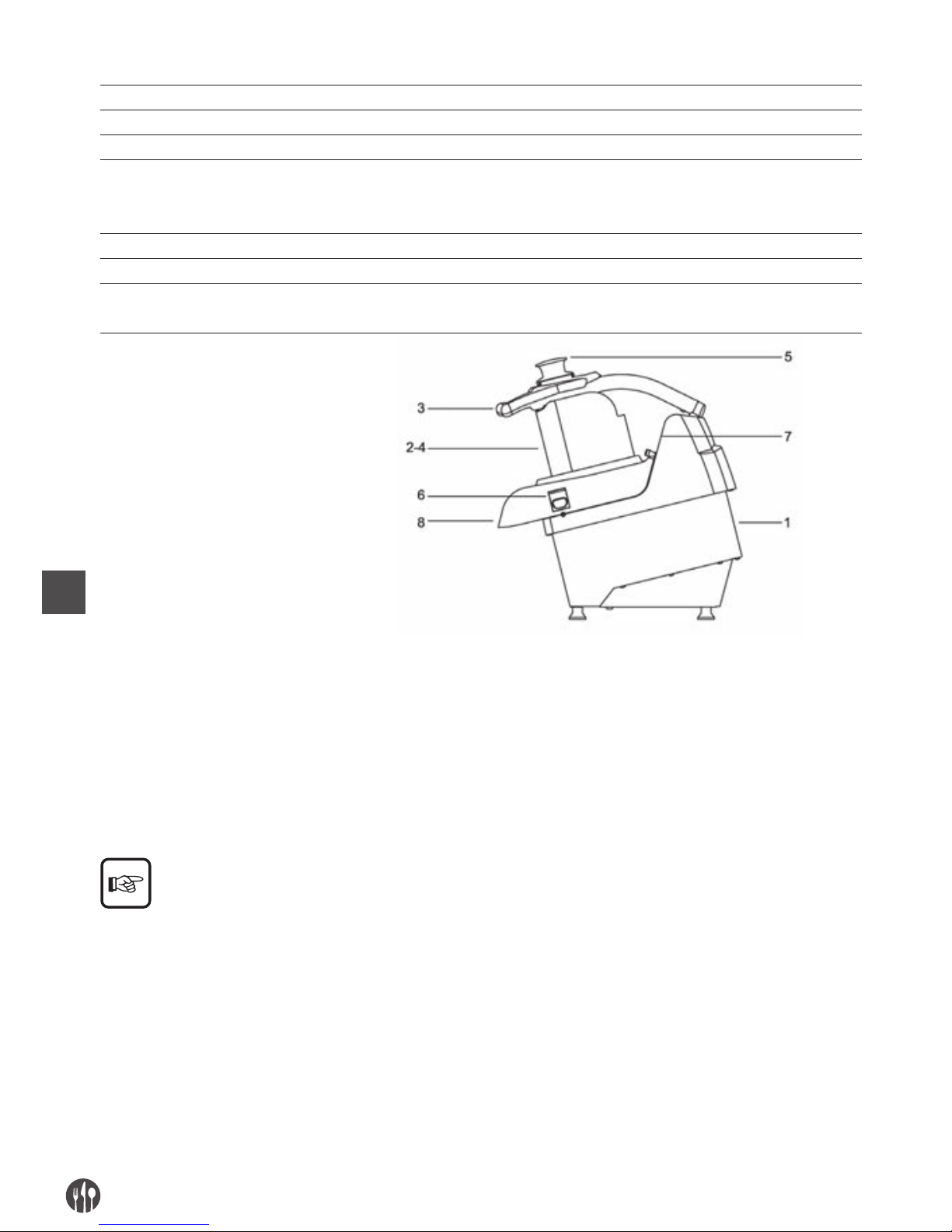
1. machine body
2. loading mouth for slices
3. pressure handle
4. loading mouth for cubes or splines
5. pestle
6. cover block knob
7. control panel
8. unloading mouth
NORMAL USE, IMPROPER USE, NOT CORRECT USE OR FORBIDDEN
The machine described in the present instructions
manual for the use is foreseen to be driver from an
only operator skilled and prepared on residual
risks, but with the competence, in safety matter, of
maintenance employees.
The operator will have to posses at least the mini-
mum age foreseen from the social laws in the
working field and to have enjoyed of the necessary
technical preparation at least from a more skilled
operator that had him preliminarily trained to the
machine correct use.
In its NORMAL USE and reasonably foreseeable, the
machine can be used only to cubes cut and grate
fruit, fresh vegetables of all known types, cour-
gettes, carrots, celeries, potatoes, peppers, tomatoes, etc… and others of same solidity.
The machine must not be used IN IMPROPER USE; in particular:
• it must not be used for domestic use,
• it must not functioned with parameters different
from those showed in the technical characteristics table,
• for every use of the machine with modalities different from those showed in the present manual,
the manufacturer declines every responsibility,
• the user is responsible of the damages resulting
from the lacked exercise conditions observance in
accordance with the agreed technical specifications and order confirmation,
• the discs must be of the showed configurations,
• introduce dry and not humid or undraining food
products,
• not tamper or damage intentionally nor remove or
hide the labels.
The machine must not be used IN NOT CORRECT WAY or FORBIDDEN so some damages or injuries
could be caused for the operator; in particular:
• it is forbidden to move the machine when it is con-
nected the electric feeding;
• it is forbidden to draw the electric feeding cable
or the machine to disconnect the feeling plug,
• it is forbidden to put weights on the machine or on
the electric feeling cable,
• it is forbidden to put the electric feeling cable on
sharp parts or with burn danger,
• it is forbidden the machine use with the damaged
and not integer electric feeding cable or with the-
Page 7
EN
7
control devices;
• it is forbidden to leave the machine off with the
electric feeding cable connected with the feeding
plug,
• it is forbidden to leave the loaded machine un-
guarded;
• it is forbidden to insert any type of object inside
the motor ventilation cap;
• it is forbidden to put the machine above different
objects from the working bench used in the food
• field of height included between 900 - 1100 mm
from the trampling level,
• it is forbidden to insert every type of object under
the machine base or place clothes or other between the machine support pressure feet and the
work bench,
• it is forbidden the use of inflammable substanc-
es, corrosive or harmful for the cleaning,
• it is forbidden to plunge the machine in water or
other liquids;
• it is forbidden the not authorized personnel use
and with clothes different from that showed for
the use,
• it is forbidden to introduce in the cutting zone and
in the unloading mouth the hands or whatever
other body part, to remove the cut food product;
• it is forbidden to introduce in the unloading mouth,
any object, as for example knifes blades, etc…,
• it is forbidden to remove the cover blocked to the
machine during the machine working or however
when the working food product has been stored,
• it is forbidden during the functioning to try to open
or lift the cover, knock down or tip over the machine, open or remove the protection case placed
on the bottom,
• it is forbidden to slacken the cover block knob
blocked to the machine both during the working
and however before 5 sec from the machine stop
control,
• it is forbidden the functioning with the fixed and
moving protection shelters not blocked correctly or removed;
• it is forbidden the partial removal of the protections and the danger signals.
• it is forbidden the functioning without that all the
precautions about the residual risks elimination
• have been adopted on behalf of the user,
• it is forbidden to smoke or use free flame devices
and manipulate incandescent materials, unless
some suitable safety measures aren’t adopted,
• it is forbidden to activate or set the control and
blockage devices as knobs or similar both during
the machine functioning both if you aren’t authorized.
The user is however responsible of the damages resulting from the lacked observance of the specified
normal use conditions. For possible doubts contact to the Authorized Assistance Centre.
CAP. 3. SAFETY INSTRUCTIONS
INTRODUCTION
The lacked standards and safety procedures applications can be danger and damage sources.
The machine means bound in the use for the re-
spect, on behalf of the final user, of:
• all rules, of insertion in the environment and of
people behavior, fixed from the laws and/or appli-
cable standards; with particular reference to the
fixed plant upstream of the supplied machine and
for its connection/functioning;
• all further instructions and use warnings making
part of the technical/graphic documentation annexed to the same machine.
Page 8
EN
8
Except where differently specified, the personnel
that performs the installation interventions, connection, maintenance, reassembly and reuse,
damages or breakdowns, demolition and disman-
tling must be a skilled personnel trained in safety
matter and educated on the residual risks, with the
competencies, in safety matter, of the maintenance
employees.
ENVIRONMENTS, WORKING AND PASSING PLACES
The work environment must answer to the directive
89/654/CEE. In the working area foreign objects
must not be present. The employer, in the directive
89/391/CEE respect, concerning the measures real-
ization turned to promote the safety and workers
health improvement during the work, must provide
to eliminate or reduce the showed residual risks as
foreseen in the present manual.
WARNINGS ON THE RESIDUAL RISKS
RESIDUAL RISK DUE TO THE FIXED, MOBILE PROTECTIONS REMOVAL, INTERVENTIONS ON BROKEN/
WORN PARTS
For any occasion the operator must not try to open
or remove a fixed or mobile protections or camper
a safety device.
In the phase of equipment, maintenance, tools
change and cleaning, and during all further manual
operations that happen introducing the hands or
other body parts in the machine dangerous areas,
a residual risk remains due above all to:
• knocks with machine manufacturing parts,
• grazing and/or abrasion with machine rough parts,
• sharp pain with the sharpened parts,
• cut with tools sharpened parts.
Besides in the loading phase, with the lifted pres-
sure that happens also introducing the hands within
the machine dangerous parts, remains a residual risk
due above all to a cut with tools sharpened parts.
Besides in the phase of cleaning or pieces unblock
inserted in the discs that happens also introducing
the hands near the cutting blades, remains a residual risk due above all to a cut with tools sharpened
parts.
The operator and the maintenance man must be
trained for the intervention connected to the manual operations with open repairs, must be trained
on the connected consequent risks, must be authorized from a responsible person and must use adequate individual protection devices, five fingers anti
cutting gloves. All interventions on the discs must
happen keeping them with the blades directed to-
wards the bottom.
PROTECTION DEVICES ON THE MACHINE
The machine safety devices and protections must
not be removed.
If they must be removed for extraordinary maintenance requirements will have to be immediately
taken some measures ready to put in evidence and
to reduce at the possible minimum limit the danger
that can derive from it.
The protection or the safety device replacing must
happen as soon as the reasons, that are necessary
to their temporary removal, are finished.
All machine safety and protection devices, both
electrical both mechanical, must be maintained in
perfect and constant efficiency conditions.
Page 9
EN
9
The machine transmission devices are completely
isolated through fixed protections that don’t allow
the access to any kinematical chain.
For all safety functions including the control and
check systems, the components and well checked
safety principles have been used.
responsible person and must use adequate individual protection devices, five fingers anti cutting gloves.
All interventions on the discs must happen keeping
them with the blades directed towards the bottom.
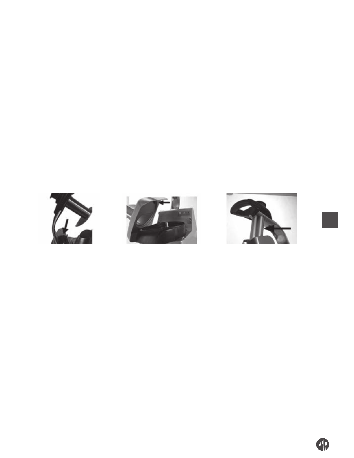
TOOLS POST GROUP:
1. Taken into consideration of the machine use modalities and of its use destination, the mobile elements are both isolated from fixed shelters, mobile ones or other safety devices, placed at the
distances from the access points such why dangerous points aren’t reachable;
2. on the handle and pressure group is placed a micro switch that stops the tools rotation when it is
possible to access through the loading mouth;
3. the loading mouth to cut, presents an adequate
length: the tools result be placed at the distances
from the access points such why aren’t reachable;
4. on the cover of the machine superior zone is placed
a micro switch that stops the tools rotation when
it is possible to access through the loading zone;
5. in the unloading zone in correspondence of the
product exile, the particular expeller disc conformation and the rotating discs doesn’t allow to the
hand or part of it to reach the parts in movement
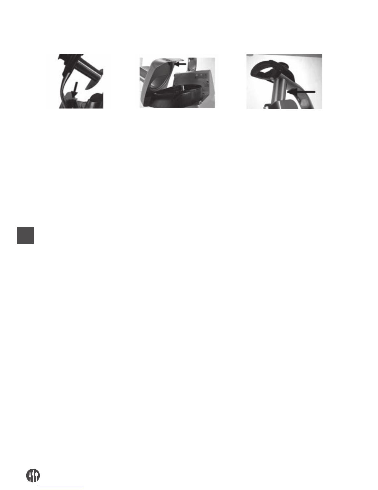
and however parts with dangerous points;
Pressure handle
with micro switch
Dismantled superior cover
with micro switch
Loading mouth fixed
shelter to cut
CAP. 4. TRANSPORTATION, PUT ON SERVICE AND USE
WORK PLACES AND OPERATORS TASKS
As described in the instructions manual for the use, the machine is designed to be driver from an operator
trained and qualified on the residual risks, but with the competences, in matter of safety, of the maintenance employees.
The work normal zone of the operator is:
1. The machine lateral zone near the loading mouths
(defined loading zone) in functioning normal conditions for the manual loading operations of the
food product and during the pestle use to convey
the food product within the machine neck, with the
fixed and mobile shelters in closed and blocked
position;
2. The machine anterior zone near the food product
loading zone in functioning normal conditions for
the manual withdraw of the food product stored in
an appropriate container, with the fixed and mobile shelters in closed and blocked position.
Page 10
EN
10
PREPARATION PRELIMINARY OPERATIONS
STABILITY
The machine stability is designed so that, in the foreseen functioning conditions, taking into considerations of the climatic conditions, is such to allow the use
without the pouring risk, falling or untimely moving.
Taking into consideration of the conformation and its
position, the machine results to be essentially
steady without needs of work bench fastening.
All support pressure feet placed under the base
must support on a solid surface, uniform and well
leveled.
ELECTRICAL FEEDING
The electrical feeling connection must be in conformance with the legislation relevant to the state in which
is used.
The electrical feeding must so be maintained in conformance with the following technical prescriptions:
1. the electrical feeding must be always of the type
and have an intensity corresponding to the specifications listed in the machine plate. If excessive
voltages are applied, some components will be
damaged irreparably,
2. a differential device must be foreseen coordinat-
ed with the protection circuit, respecting the legislation and the actual legislative and prescribed
disposals in the operative installation country;
3. the cable for the electrical feeding outside the
machine container, must be made pass in the
spaces prepared from You and adequately protected;
4. if present the neutral cable (N) before to feed the
electrical equipment, as for you must be guaranteed its continuity (connected and available).
5. before to feed the electrical equipment, as for you
must be guaranteed its continuity (connected and
available) of the yellow green cable of the protection equipotential circuit.
ASSEMBLY / DISASSEMBLY
The assembly / disassembly operations of any machine member are performed with the stopped machine
and with the plug disconnected to the socket, or with the sectioning device in OFF.
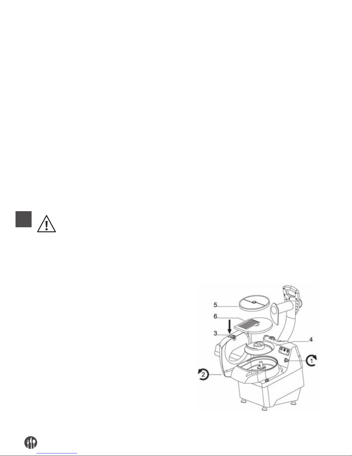
The tools assembly on the machine performs in different phases.
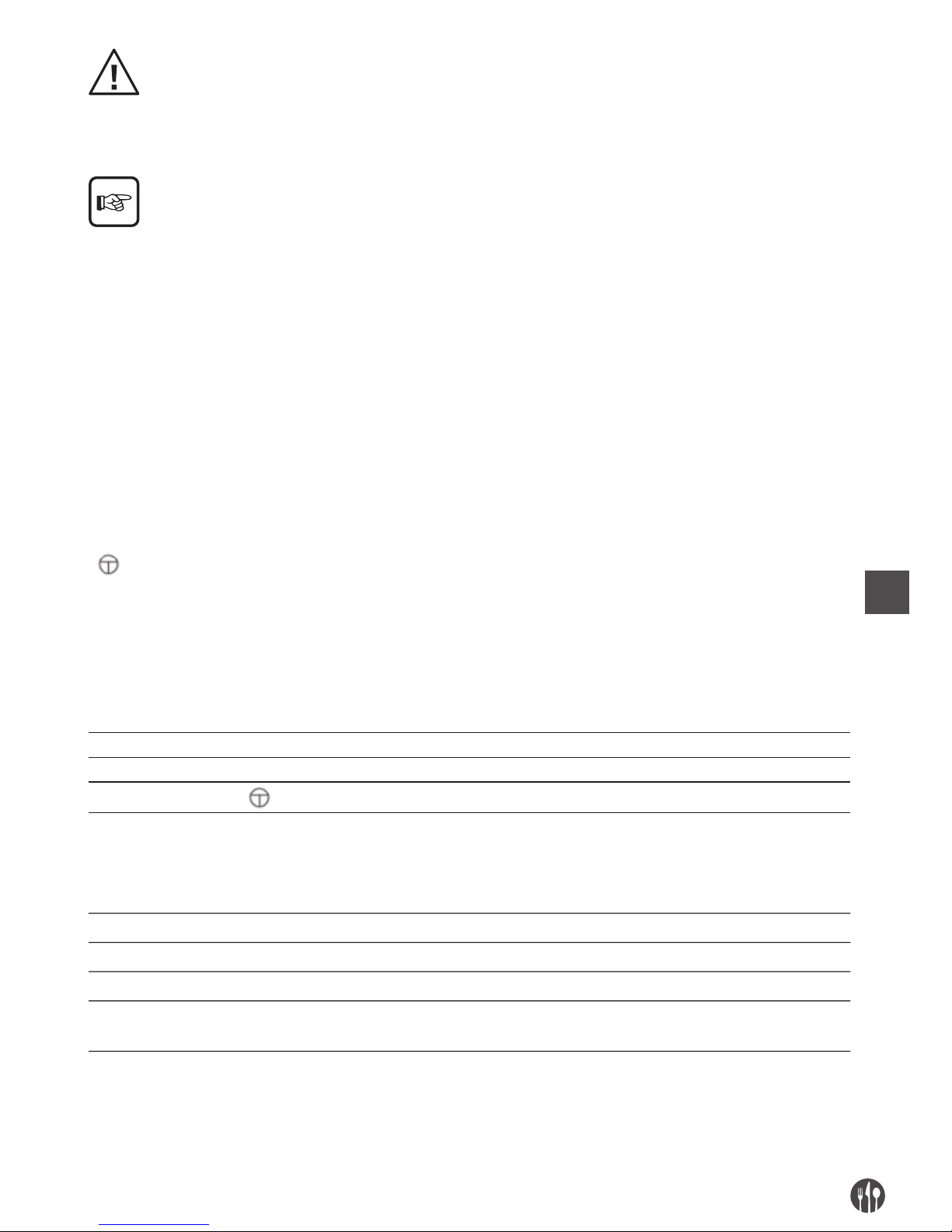
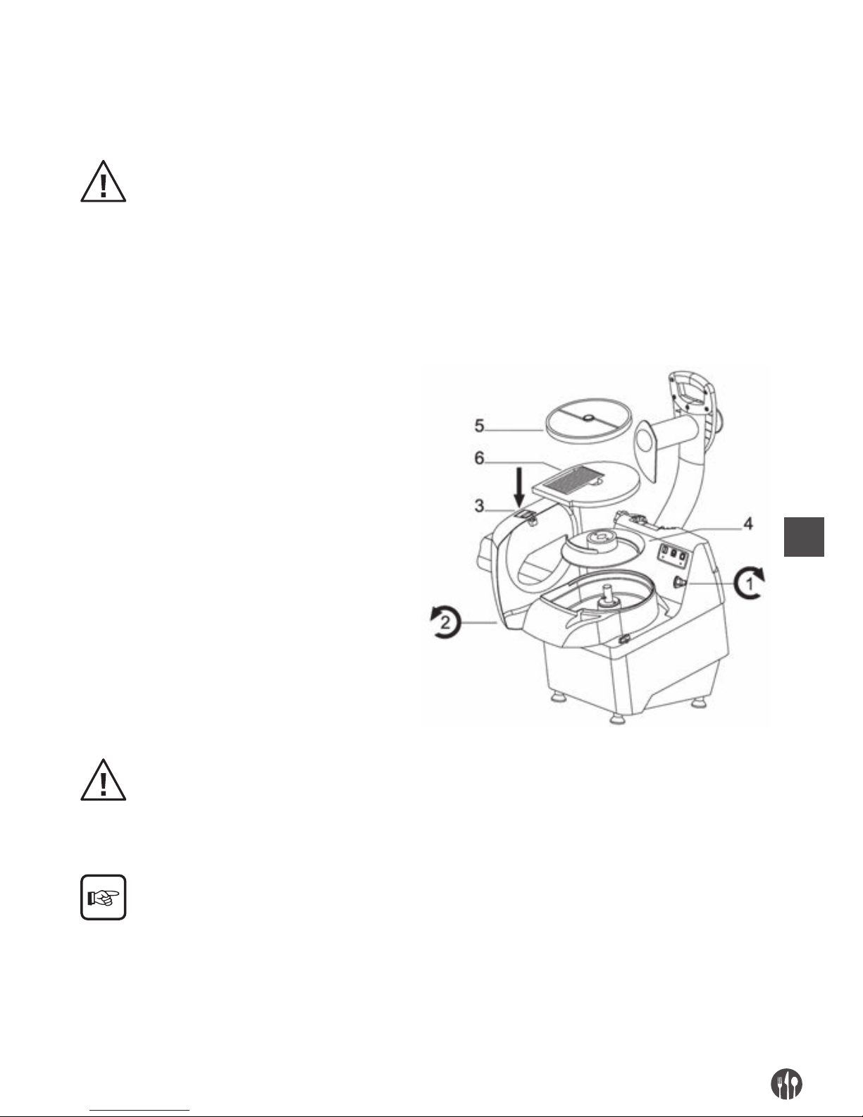
1. Rotate the block knob (1) of the superior cover (2) push
the button (3) and with the both hands rotate the superior
cover (2)
2. On the rotating hub, insert before the expulsion disc (4),
checking that the dragging pivots on the hub insert
in the holes on the disc;
3. Performing working that request the use of an only disc,
insert on the hub the rotating disc (5) over the expeller
disc (4) (see tables of the chapter n. 2)
4. Performing working that request the contemporary
use of two disc, insert on the rotating hub in sequence
the following elements: (see tables of the chapter n. 2)
1° - Expeller disc (4)
2° - Fixed disc (6)
3° - Rotating disc (5)
5. Replace the superior cover (2) rotating it
6. Tighten the block knob (1) rotating in anticlockwise
.
Page 11
EN
11
After having inserted the discs in accordance with the working requirements, check of the correct bayonet
hooking of the same in the rotating hub.
The expeller disc MUST BE ALWAYS OBLIGATORY
installed, because the discs can work in the correct
position.
For the optimum use of all rotating discs types and
the possible contemporary use of the rotating
discs
with the fixed ones, consult the tables of the chapter
n. 2, listing all possible functional combinations
The disassembly activities perform following backwards the assembly phases previously described.
CUTTING DISCS ROTATION
The here follow operations must be performed from
the machine maintenance man (personnel qualified in
the
electrical maintenance sector of the industrial machines).
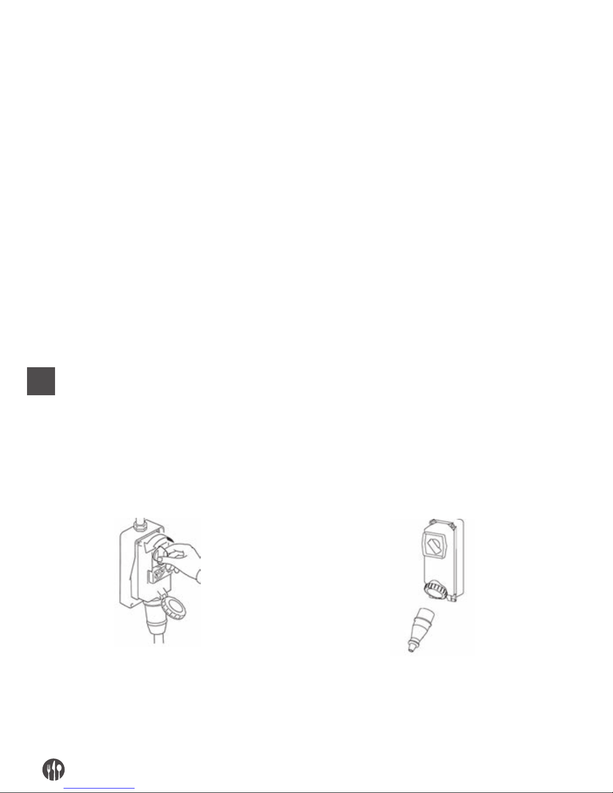
For machines fed with three phase voltage (3 PE AC
400V 50Hz), push the maintained action control button
“
”, and verify the correct way of the cutting discs
rotation through the loading mouth to cut, comparing it
with the way showed from the arrow (anticlockwise
way) placed on the machine cover.
If there is a rotation in the opposite way to that one of
the arrow (clockwise way), switch off the machine
disconnecting the plug, disassembly it, disconnect two
phase cables and invert them of position.
FUNCTIONING DESCRIPTION
The control devices are designed and manufactured
so as to be sure and reliable and resistant to the normal stresses of service, to the foreseeable efforts
and to the external agents. They are besides visible,
identifiable and labeled from a suitable mark.
Here follow the following control devices are listed:
TYPE / COLOR REFERENCE / DECRIPTION
Button / black “O ” / Button for the machine stop control
Button / white “ I ” / Button for the machine starting control with impulse
Button / white ” ” / Button for the machine starting control with maintained action
SIGNALS
TYPE / COLOR REFERENCE / DECRIPTION
Red fixed led Machine fed with superior cover closed and pressure lowered
Red flashing led Machine fed with superior cover opened
Green fixed led Machine fed in function
Green flashing led Machine fed with machine starting button pushed and pressure lifted to
the lowering of the pressure the machine starts (green fixed led)
Page 12

EN
12
STARTING
The machine starting with impulse is possible only
with a voluntary action on the control device fore-
seen for this aim: white button “I” for the machine
starting control.
STOP
For the stop control push the black button “O”. In
case of temporary or prolonged stop, before to replace in function the machine, all fed products must
be taken away within the machine: follow the indications about the grinding group disassembly.
MANTAINED ACTION STARTING
The machine maintained action starting is possible
only with a voluntary action on the control device
foreseen for this aim: white button “
” for the
machine starting control. When the button releases
the machine stops.
VOLTAGE ABSENCE
In case of electric feeling break or if the machine is
disconnected from the electric net, this last one will
be able to be restarted only following the starting
function, after the electric feeding back or the elec-
tric net refasten.
PRESSURE OPENING
Lifting the pressure for the handle, the machine
stops immediately for the entry in function of the
safety micro switch. The machine can be restarted
only lowing the pressure up to the height that doesn’t
allow the introduction of the fingers towards the cutting zone and following successively the starting
function.
MACHINE COVER REMOVAL
Slacking the block knob and removing the cover with
the hands, the machine stops immediately for the
entry in function of the safety micro switch. The ma-
chine can be restarted only repositioning the machine cover and blocking it with the appropriate knob
and following successively the starting function.
CHECKS AND VERIFICATIONS BEFORE STARTING
VERIFICATION / CHECK MODALITY AND COMPARISONS
Check that:
• There aren’t on the machine,
within the loading mouths
and in correspondence of the
unloading mouth, product
exile zone, stranger objects
Sight control of the indicated parts, to check of objects or extraneous bodies
lacking as for example different tools, clothes, etc … and that there isn’t
however the food product.
In case of presence provide to their removal.
Check the cleaning:
• of the machine internal parts
• the cutting zone, the discs,
the machine cover internal
part, the unloading mouth
• the pressure and the pestle
• of the machine external
surface
All indicated parts surfaces, before the machine use must be checked visually
to verify their cleaning.
For the sight control of the cutting zone internal parts remove the superior
cover.
In case of molds presence or other type of dirtiness, provide with the cleaning
procedure in accordance with the charter 5 indications.
Page 13

EN
13
Check the integrity:
• of the fixed protections
• of the closure superior cover
• of the loading and unloading
mouths of the pressure
• of the machine body
All fixed protections, etc.. must perform the function for which have been
foreseen. Indicated parts sight check to verify their integrity in their surface
external part. The parts must be however changed at the first erosion signals
or breaking (cfr. Authorized Assistance Centre).
Check the functionality:
• of the control system parts /
control about the safety;
• of the control devices
All devices must perform the function for which have been foreseen. Control
directly the devices so that these ones determine the waiting function.
The actuators and all parts must be however changed to the first erosion signals
or breaking (cfr. Authorized Assistance Centre).
Check the absence:
• of strange noises after
the starting
During the functionality checking of the control devices, if there are strange
noises, due for example to a seizing or mechanical breaks, stop immediately
the machine and activate the maintenance service.
For any intervention type or for the parts change that
are damaged, activate the maintenance service.
The possible change must happen with manufactu-
rer original products or at least of quality, safety and
equivalent characteristics. For analysis contact the
Authorized Assistance Centre.
PUT IN FUNCTION
The machine operator can put in function the machine following in order the under reported indications:
• Positive controls result for the preparation preliminary operations,
• Positive controls result for the electric feeding,
• Plug connection in opportune current socket,
• Positive controls result for the assembly (discs
positioning control, etc…),
• Positive controls result for the discs correct rotation,
• Positive controls result / checks before the starting,
• Positive controls result finalized to check the respect of all safety conditions,
• Place the cover in the machine superior zone and
tighten the block knob;
• Place in a harvest basin in the machine anterior
zone in correspondence of the food product unloading mouth;
• Place in the machine left zone and start it activa-
ting the control device of START “I”,
• Introduce manually the feed product within the
loading mouth in accordance with the working
requirements and push it towards the low / cutting zone or lowing gradually the pressure handle
or pushing it with the equipment pestle, making a
light pressure to obtain the better operative result, without submit with anomalous effort the
transmission parts. When the pressure or the
pestle come to the stoke end, lift them and repeat
the above described operations carrying on up to
the work cycle completion,
• At the end of the feed product introduction, or
when from the unloading zone doesn’t exile more
the product, stop the machine activating the control device of STOP “O”.
SWITCHING OFF
In succession, the switching off operations must follow what here under indicated:
• before the switching off wait the feed product exile conclusion from the unloading mouth pushing
completely towards the low the pressure handle
and the pestle,
• stop the machine working the control device of
STOP “O”,
• disconnect the machine plug from the feeding
socket,
• perform the cleaning interventions.
Page 14
EN
14
UNBLOCK IN CASE OF STUMBLING BLOCK
During the working, or during the tool rotation, due:
• to the feed products introduction with not homogeneous parts,
• to the excessively hard and dry products introduction, the machine could block.
The same situation can determine after an electric
feeding damage, or when the machine is stopped
with the feed product inside it.
To resume normally the working the discs must be
removed: the disassembly must follow the pre-
scriptions previously indicated.
CAP. 5. MAINTENANCE, DAMAGES RESEARCH AND CLEANING
MAINTENANCE MAN REQUIREMENTS
With the word “maintenance” it must not be intended only the periodic check of the machine normal
functioning but also the analysis and the consequent
remedy of all those causes that for any reason put it
out of service. It is absolutely necessary that for the
activities of maintenance, cleaning, parts change
and damages research performed from the user,
this task is entrusted to skilled people, competent
and authorized from the employer.
All operations of maintenance, cleaning and parts
change, none excluded, must be peremptorily performed with the machine completely stopped and
insulated from the external feeling sources.
MAINTENANCE PRESCRIPTIONS
SHELTERS REMOVAL AND/OR PROTECTION DEVICES
For some intervention of the present charter, it is
necessary to remove from their position some
fixed shelters.
The removal can happen only from the maintenance
man.
At the end of the interventions, these shelters must
be replaced and blocked in their original position,
with the fastening systems that were foreseen before the intervention.
The maintenance responsible must deactivate completely the machine, as here follow showed, before to
proceed to the fixed shelter removal and/or to the element change.
INSULATION FROM THE EXTERNAL FEEDING SOURCES
Before to perform any operation of maintenance, cleaning and parts change, the external feeling sources
must be dissected and insulated.
Position to “zero” the protection device placed to the
bottom of the electric equipment feeding line.
Disconnect the general sectioning device and provide to protect the plug with appropriate systems
Page 15

EN
15
DAMAGES RESEARCH OR FAILURES AND MOBILE ELEMENTS UNBLOCK
Here follow are indicated he interventions for the damages research or failures and mobile elements unblock that can be performed from maintenance men.
TYPE POTENZIAL/S CAUSE/S MODALITY AND COMPARISONS
Net voltage
lacking
General black out Contact the electric energy distributor.
Fuses or magneto thermals
intervention placed to the bottom of
the machine feeding line
After having eliminated the causes that have
determined the protection device
intervention, restore it. In case of problem
persistency contact an electrician technician.
Functioning
intervention
Protection device intervention inside
the machine
Contact an electrician technician: after to have
eliminated the causes that have determined the
protection device interventions, restore it.
In case of fuses interventions, change it with
types of the same model, calibration and
intervention curve.
Pressure handle lifting
(flashing green led)
Lifting the pressure handle, the machine stops
immediately for the entrance in function of the
safety micro switch.
Lower the pressure up to the height that doesn’t
allow the fingers introduction towards
the cutting zone.
Removel of the superior cover
(flashing red led)
Removing the superior cover, the machine stops
immediately for the entrance in function of
the safety micro switch.
Place correctly the superior cover and block it
with the appropriate knob and start the machine.
Cause/s not identifiable
Contact directly the Authorized Assistance Centre
The machine
doesn’t function:
the discs don’t
rotate or don’t
perform correctly
the cutting
Feeding tension lacking
(all led switched off)
Check and restore the electric energy.
Sectioning devices on “O”
(all led switched off)
Turn the sectioning devices in the position “ON”
Fuses intervened or not functioning
magneto thermals.
Make change the intervened fuses, check
the magneto thermal switches condition.
Lacked functioning of the run button Check the efficiency of the button of “I”
and eventually contact directly the Authorized
Assistance Centre.
Micro switch damaged Contact directly the Authorized Assistance
Centre
Cutting discs worn or ruined Contact directly the Authorized Assistance
Centre
Slow drive belt determines also noise
emission or creaking
Contact directly the Authorized Assistance
Centre
Page 16

EN
16
EXTRAORDINARY MAINTENANCE
For the intervention of extraordinary maintenance,
consequent to breaks or revisions or mechanical
and electric damages, (for example the movement
drive belts tensioning, etc…), it is necessary an intervention request directly to the Authorized Assis-
tance Centre.
The instructions about the extraordinary maintenance don’t appear in the present instruction manual for the use and so must be explicitly requested to
the manufacturer.
CLEANING
It is forbidden to clean by hand the parts and the
elements in movement.
All cleaning intervention must be started only and
exclusively, after having unloaded the machine with
the food product in working and having insulated
from the electric feeling source and from external
energy.
The machine, the electric equipment and the machine board components must not be ever washed
using water, and not in any kind of jets from and
quantity; so, without “bucket” nor “rubber” nor
“towel”.
Don’t put ever directly the machine in the sink or under the tap.
The machine hygiene level classification and the associated equipment, for the foreseen use, are 2 (two):
machine that, after a hygiene risk evaluation, is in conformance with the applicable international standards
requirements, but requests a programmed disassembly for the cleaning.
FREQUENCY PERSONNEL MODALITY
At the end of every
shift work and however
before the daily use
Operator All the surface and the machine parts destined to come in contact
with the food product or with the food zones (internal surface of the
loading and unloading mouths, the pressure, the pestle, the cutting
zone, the rotating and fixed discs, the superior cover, the fixed shelters) and the jets zones (machine external surface), must be
cleaned and disinfected with the under reported modalities. For the
cutting group disassembly activities see the previous descriptions.
• Scrape the surface from the possible food product residuals
(for example with plastic scrapers);
• Clean all the food zone surfaces and jets zone with a morbid
dampened clothes (not draining) with detergent diluted in hot
water (also common soap for dishes is good).
Don’t soak them. Use specific products for steel that must be liq-
uids (not in cream or pastries however abrasive) and above all
must not contain chlorine. Against the fat substances the denatured alcohol can be used.
• Rinse with cleaned hot water and successively dry all food zone
surfaces and jets zone with soft clothes that don’t lose coats.
• The parts in stainless steel can be washed also in dishwater.
• The reassembly must happen only following working require-
ments, leave the pieces wrapped up in soft dray clothes that don’t
lose coats.
PERIODS OF LONG INACTIVITY
• During the machine long inactivity periods provide to pass vigorously on all steel surfaces (especially if stainless) a clothes
soaked of Vaseline oil so that to spread a protective veil.
Page 17
EN
17
THINGS NOT TO DO BEFORE OR DURING THE CLEANING:
• Enter towards the moving elements without to be previously
checked of their stop;
• Enter towards the moving elements without have stopped it in
guaranteed safety (blockage in zero position of the electric feeding sectioning devices)
PRODUCTS NOT TO USE:
• Compressed air with jets towards the zones with flour warehouses and in general towards the machine;
• Vapor equipment;
• Detergent that contains CHLORINE (also if diluted) or its compounds as: the bleach, the muriatic acid, products to clear the drain, products for the marble cleaning, in general decalcifying, etc,
can attack the steel composition, staining and oxidizing it unavoidable.
The only above described products fumes can oxidize and in any
case corrode the steel;
• Steel wool, brushes or abrasive discs produced with other metals or alloys (ex. Common steel, aluminum, brass, etc…) or tools
that have previously cleaned other metals or alloys, that except to
scratch the surface.
• Detergents in abrasive dust;
• Fuel, solvents or inflammable and/or corrosive fluids;
• Substances used to clean the silver.
DISASSEMBLY/ASSEMBLY
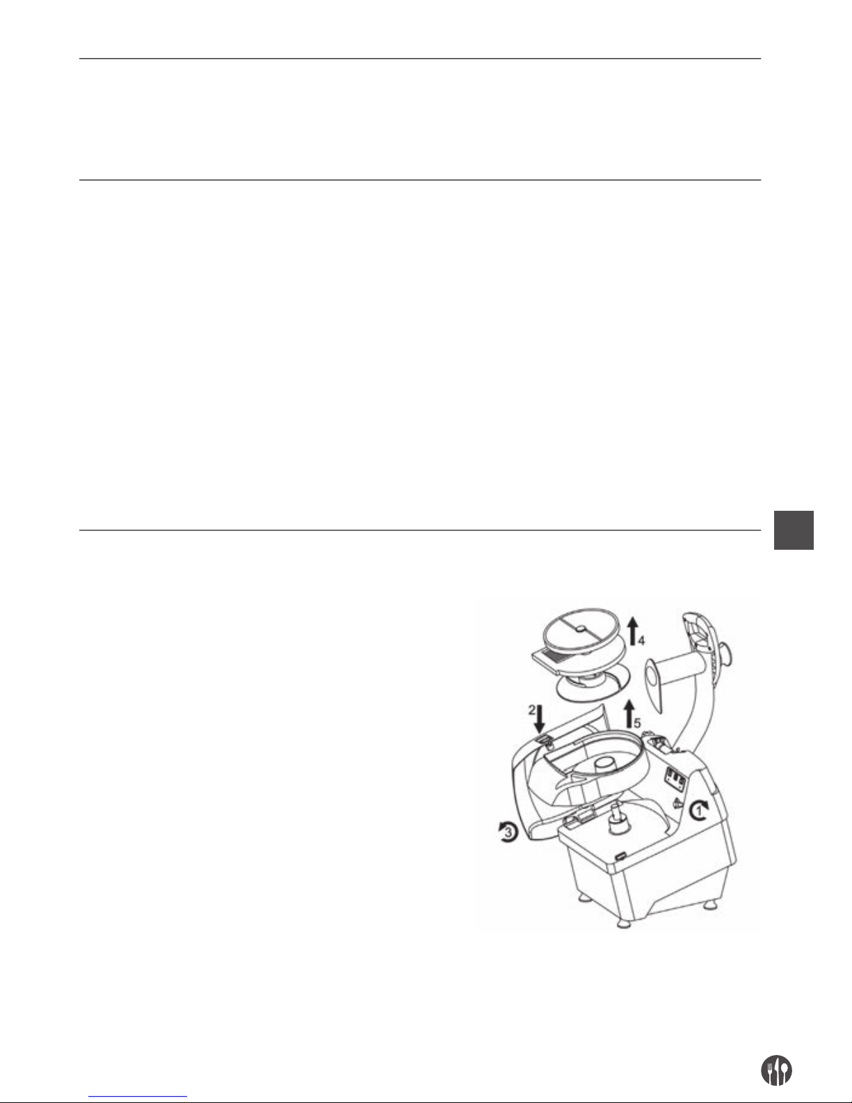
1. Rotate the block knob (1) of the superior cover push
the button (2) and with the use of both the hands rotate
the superior cover (3)
2. Extract from the rotating pivot the cutting discs
(rotating and fixed) and the expeller disc (4), remove
the plastic tub (5).
Page 18
EN
18
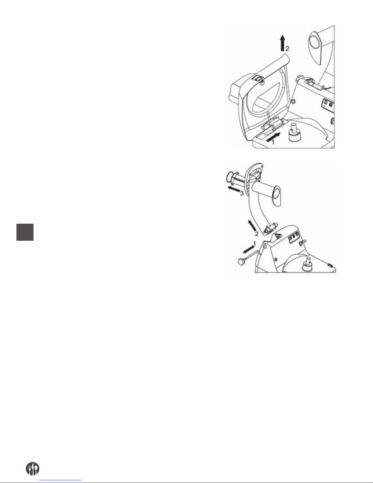
3. Remove (2) the superior cover taking
off it from the pivot on which rotates (1)
4. Put the stroke end pressure handle.
5. Take off the safety pivot (1)
6. Unhook from own seat the pressure
handle (2) lifting it towards the top
7. Rotate and so extract the pestle (3).
CAP. 6. SELLING
If we decide to use never the machine because obsolete and/or irremediably damaged or worn to the
point that the repair is anti economic, it is necessary
to proceed to its out of service without potential dangers. The out of service must be entrusted to speci-
alized and equipped personnel.
At the end of the selling activities all identification
labels and every other machine document must be
destroyed.
The machine can be sold without reducing it in mi-
nute pieces; it is sufficient to disconnect the main
groups that compound it and put them on the selling
transportation mean.
Provide to their selling operating in conformance
with the actual standards, contacting the qualified
organisms and/or to companies specialized in the
industrial scraping and/or in the refusals selling,
because there is the separation between plastic material, metallic material and electric components
that must be sent to wastes separation.
It is obliged of the employer to know of the actual laws of its country and work so as to follow this legislations.
Page 19

EN
19
It is forbidden and besides have sanctions, abandon the machine and the electric equipment in the environment.
The crossed rubbish skip symbol showed on the machine shows that the product at the end of its useful life
nust be picked up separately from the other refusals.
The user will have, so, to give the machine to the suitable waste deparation centers of electronic and electrotecnics disposals.
CAP. 7. MANUFACTURING MATERIALS
In accordance with the functioning and production requirements, the machine can be constituted with different typologies of manufacturing materials.
GROUP MATERIALS TYPOLOGY
Stainless steel Stainless steel Plastic for foods Aluminum treated
18/8 AISI 304 for foods
Machine body •
Superior removable cover •
Loading mouth •
Unloading mouth •
Rotating discs • • •
Cutting elements of the rotating discs
•
Fixed discs • • •
Cutting elements of the fixed discs •
Expeller disc •
Pestle
•
Pressure
•
Superior cover
•
Cutting basin
•
Page 20

DE
20
INDICE
KAP. 1. INHALT UND BENUTZUNG DER BEDIENUNGSANLEITUNG ......... 21
KAP. 2. ALLGEMEINE INFORMATIONEN UND EIGENSCHAFTEN............... 22
KAP. 3. SICHERHEITSANLEITUNGEN ......................................................... 26
KAP. 4. TRANSPORT, INBETRIEBNAHME UND VERWENDUNG ................. 28
KAP. 5. WARTUNG, FEHLERSUCHE UND REINIGUNG ............................... 33
KAP. 6. ENTSORGUNG ................................................................................. 37
KAP. 7. BAUMATERIAL ................................................................................. 38
Page 21

DE
21
CAP. 1. INHALT UND BENUTZUNG DER BEDIENUNGSANLEITUNG
ZIEL DER BEDIENUNGSANLEITUNG
WICHTIGKEIT DER BEDIENUNGSANLEITUNG
Das vorliegende Bedienungshandbuch ist als ganzheitlicher Teil des Geräts zu betrachten:
• Für die ganze Lebensdauer des Geräts muss es
aufbewahrt werden
• Beim Verkauf des Geräts muss das Handbuch mit
dem Gerät ausgeliefert werden
• Im Handbuch befinden sich neben allen für das
Bedienpersonal nützlichen Informationen auch
die Schaltpläne (in spezifischen Kapiteln zusammengefasst), welche für allfällige Wartungs- und
Reparatureingriffe benötigt werden.
ZIEL DER BEDIENUNGSANLEITUNG
Die Bedienungsanleitung hat zum Ziel, dem Kunden
alle nötigen Informationen zu vermitteln, die ihm
eine geeignete Anwendung und eine möglichst sichere und selbständige Handhabung des Geräts erlauben.
Außerdem wurde das vorliegende Handbuch mit
dem Ziel erstellt, Hinweise und Warnungen zur besseren Kenntnis des Geräts, sowie der Grundlagen
und Einschränkungen für dessen Betrieb zu geben.
Bei Zweifeln wenden Sie sich bitte an die anerkannte
Kundendienststelle.
ZIELPUBLIKUM
Das vorliegende Handbuch, von dem 1 Ausgabe als
vollständiges Bestandteil des Geräts geliefert wird,
richtet sich an die Bediener sowie an mit der Installation, dem Betrieb und der Wartung beauftragte,
qualifizierte Techniker.
Die für den Arbeitsschutz im Betrieb verantwortli-
che Person und die anderen Mitarbeiter für die das
Gerät bestimmt ist, müssen das vorliegende Handbuch einsehen, damit sie alle vorgeschriebenen
technischen und organisatorischen Maßnahmen ergreifen können.
HAFTUNG
• Falls das Handbuch beschädigt wird oder verlo-
ren geht, kann eine Kopie davon bei der aner-
kannten Kundendienststelle beantragt werden.
• Das vorliegende Handbuch widerspiegelt den
Stand der Technik zum Zeitpunkt der Herstellung
des Geräts; der Hersteller behält sich das Recht
vor, die Produktion und dementsprechend die anderen Ausgaben des Handbuchs zu aktualisieren
ohne die Verpflichtung, frühere Produktionen
oder Handbücher zu aktualisieren, außer in besonderen Fällen, die die Gesundheit und die Sicherheit von Personen betreffen.
• Besondere Aufmerksamkeit sollte den Restrisi-
ken an dem Gerät und den Vorschriften für die
Bediener gewidmet werden.
• Der Hersteller haftet für das Gerät in seiner Ori-
ginal-Konfiguration.
• Der Hersteller haftet nicht für Schäden, die durch
Missbrauch oder falsche Anwendung des Geräts
oder des Handbuchs entstehen könnten, ebenso
wenig für Schäden die durch Nichtbeachtung von
zwingenden Vorschriften, Nachlässigkeit, Unerfahrenheit, Unvorsichtigkeit oder Nichtbeachtung
der Verordnungsbestimmungen seitens des Arbeitgebers, des Bedieners oder des Wartungstechnikers und für eventuelle Störungen durch
unvernünftigen Gebrauch, Missbrauch und/oder
unzweckmäßigen Gebrauch entstehen könnten
• Der Hersteller haftet nicht für Folgen aus der An-
wendung nicht originaler oder nicht gleichwertiger Ersatzteile.
• Der Hersteller haftet nur für die in der italieni-
schen Originalversion enthaltenen Informationen.
• Die Nichtbeachtung der in diesem Handbuch enthaltenen Vorschriften verursacht das sofortige
Entfallen der Garantie.
Page 22
DE
22
Die Werksverantwortlichen sind im Rahmen der ihnen zugeteilten Befugnisse und Kompetenzen für
folgende Punkte zuständig:
• Umsetzung der vorgeschriebenen Sicherheitsmaßnahmen;
• Die Arbeiter über die spezifischen Risiken, denen
sie ausgesetzt sind, und über die wichtigsten
Schutzund Vorsorgemaßnahmen unterrichten;
• Anordnen und verlangen, dass die einzelnen Mitarbeiter die Sicherheitsvorschriften beachten und
die ihnen zur Verfügung gestellten Schutzausrüstungen benutzen:
– Mehr als einen Mitarbeiter gleichzeitig auf dem
Gerät arbeiten lassen.
SYMBOLERLÄUTERUNG
Im Folgenden werden die Bedeutungen der in diesem Handbuch benutzten Symbole und Begriffe erläutert.
GEFAHR
Weist auf eine Gefahr hin für den Bediener des Geräts und für alle, die sich in der Nähe des
Geräts befinden.
Daher sollte die aufgezeigte Tätigkeit unter Beachtung der geltenden Unfallverhütungsvorschriften und der im vorliegenden Handbuch angegebenen Maßnahmen ausgeführt werden.
HINWEIS
Weist auf nützliche und/oder zusätzliche Empfehlungen hin und/oder auf besondere Maßnahmen bezüglich der gerade auszuführenden Tätigkeit.
ACHTUNG
Weist auf einen Arbeitsschritt hin, der zur Verhinderung einer Beschädigung am Gerät mit
Sorgfalt ausgeführt werden soll.
CAP. 2. ALLGEMEINE INFORMATIONEN UND EIGENSCHAFTEN
ANWENDUNG UND BAUTEILE
Der Gemüseschneider, nachfolgend „Gerät“ genannt, kann zum Schneiden, Würfeln und Raspeln von Obst,
frischem Gemüse aller Art (Zucchini, Karotten, Sellerie, Kartoffeln, Peperoni, Tomaten etc....) und ande-
ren Lebensmitteln ähnlicher Beschaffenheit verwendet werden.
Das Gerät besteht aus einem elektrischen Motor,
der in einem einzigen Guss eingefügt ist (Grundgerät), in dem die Motorwelle mit dem jeweils benutzten Schneidwerkzeug über Antriebsriemen verbunden ist.
Die Lebensmittel können von Hand auf verschiedene
Arten in das Gerät eingeführt werden:
1. Zum Würfeln, Zerfasern oder in Streifen Schnei-
den durch die Einfüllöffnung, die sich im oberen
linken Bereich des Geräts befindet und danach
ebenfalls von Hand durch Betätigung des Press-
hebels, wodurch das Produkt gegen den Schnittbereich gepresst wird. Die Produkteinführung
sollte in gemäßigten Mengen erfolgen, damit bei
Senkung des Pressers eine Ausschaltung des Ge-
räts durch Ansprechen des Sicherheitsmikroschalters im Presserbereich verhindert wird.
2. zum Schneiden werden Produkte durch die Ein-
füllöffnung im oberen rechten Bereich des Geräts und ebenfalls von Hand mit dem Stopfer in
den Gerätehals gegen den Schnittbereich eingeführt. Der Stopfer besteht aus Kunststoff, der für
die Berührung mit Nahrungsmitteln geeignet ist.
Die Einfüllöffnung zum Würfeln und die Einfüllöffnung zum Schneiden befinden sich auf dem Deckel,
der an dem Gerät mit einem entsprechenden Knauf
befestigt ist: Auf dem Gerät befindet sich ein Sicherheitsmikro, der die korrekte Position des Deckels
erfasst.
Page 23
DE
23
Der Schnittbereich des Geräts stellt den Innenraum
dar, in dem von Hand bewegliche Schneidscheiben
mit Bajonettverschluss sowie andere feste Schei-
ben auf die Motorwelle montiert werden können:
• bewegliche Schneid- und Raspelscheiben;
• bewegliche Schneidscheiben;
• bewegliche Schneidscheiben zum Schneiden von
Stiften;
• feste Scheiben zum Würfeln;
• feste Scheiben zum Schneiden von Streifen;
• bewegliche Auswurfscheibe.
Im unteren vorderen Bereich des Geräts befindet
sich die Auswurföffnung, durch die das geschnittene Produkt ausgeworfen wird.
Alle Materialien, die direkt mit Lebensmitteln in Berührung kommen, entsprechen den geltenden Hygienevorschriften für Lebensmittel.
Je nach Betriebs- und Produktionsbedürfnissen
kann das Gerät mit verschiedenen Zuberhörteilen
ausgestattet werden.
Das Gerät wurde mit einem Kennschild ausgestattet, das folgende Daten enthält:
TECHNISCHE UND BAUTECHNISCHE DATEN
Motorleistung (kW) / (Hp) 0,58kW / 0,80Hp
Innenmaße Einfüllöffnung zum Würfeln (mm) 180 x 80
Halslänge Einfüllöffnung zum Würfeln (mm) 150
Innenmaße Einfüllöffnung zum Schneiden (mm) 57
Halslänge Einfüllöffnung zum Schneiden (mm) 190
Stundenleistung (kg/Std.) 250-450
Masse (kg) 21,5
Abmessungen: A x B x C (mm) 490 x 280 x 530
Äquivalenter Dauerschallpegel A Unter 70 dBA
Strombeschaffenheit - Frequenz Siehe Kennschild am Gerät
Nennleistung Siehe Kennschild am Gerät
Nominale Betriebsspannung Siehe Kennschild am Gerät
Page 24
DE
24
Spannung Hilfskreise AC 24V – DC 24V
Masse und Nulleiter/Neutralleiter TT und TN
Schutzgrad IP X3
Anwendungsort Innenraum
Gerätaufstellung Für den Lebensmittelbereich geeigneter Arbeitstisch in der Höhe
zwischen 900/1100mm vom Fußboden reichend und mit einer angemessenen
Tragkraft, bei umgebendem Freiraum von mindestens 800 mm
Max. Lufttemperatur +40°C
Min. erforderliche Beleuchtung 500 lux
Konformität Produktrichtlinien 2006/42/CE, 2006/95/CE und folgende Änderungen und Ergänzungen,
Verordn. 1935/2004
1.Gerätekörper
2. Einfüllöffnung für Scheiben
3. Presshebel
4. Einfüllöffnung für Würfel oder Streifen
5. Stopfer
6. Feststellknauf Deckelverschluss
7. Steuertasten
8. Auswurföffnung
BESTIMMUNGSMÄßIGE VERWENDUNG, MISSBRAUCH, FALSCHE ODER VERBOTENE VERWENDUNG
Das im vorliegenden Handbuch beschriebene Gerät
ist für die Anwendung durch einen einzigen Bedie-
ner vorgesehen. Dieser sollte entsprechend ausgebildet und bezüglich der Restrisiken informiert sein
und zugleich in Bezug auf Sicherheit die Kenntnisse
eines Wartungstechnikers aufweisen.
Benutzer müssen mindestens das gesetzlich vorgesehene Mindestarbeitsalter aufweisen und
müssen die nötige technische Einführung durch
einen Benutzer mit mehr Erfahrung erhalten, der
sie zuvor in die richtige Anwendung des Geräts einweist.
Bei der BESTIMMUNGSMÄßIGEN VERWENDUNG
und nach vernünftigem Ermessen zu erwartenden
VERWENDUNG kann das Gerät nur zum Würfeln und
Raspeln von Obst, frischem Gemüse aller Art, Zuc-
chini, Karotten, Sellerie, Kartoffeln, Peperoni, Tomaten etc… und weitereN Produkte ähnlicher Beschaffenheit verwendet werden.
Page 25

DE
25
Das Gerät darf nicht MISSBRAUCHT werden; im Besonderen:
• kein Gebrauch für den Haushalt,
• es darf nicht mit anderen Parametern als die in
der Tabelle zu den technischen Eigenschaften
aufgeführten betrieben werden,
• für jeden anderen als die im vorliegenden Handbuch aufgeführten Anwendungszwecke lehnt der
hersteller jede Haftung ab;
• der Anwender ist verantwortlich für Schäden, die
aus der Nichtbeachtung der Betriebsbedingungen
im technischen Datenblatt und in der Auftragsbestätigung hervorgehen,
• die Scheiben müssen den dargestellten Kombi-
nationen entsprechen,
• nur trockene und weder feuchte noch tropfende
Lebensmittel einführen.
• die Etiketten nicht absichtlich beschädigen und
auch nicht entfernen oder verbergen.
Das Gerät darf nicht AUF UNZWECKMÄßIGE bzw. VERBOTENE WEISE verwendet werden, da dies
Schäden oder Verletzungen an den Bediener verursachen könnte; im Besonderen ist es verboten:
• das Gerät bei eingestecktem Stromkabel zu ver-
schieben.
• das Stromkabel oder das Gerät zu ziehen um das
Gerät vom Stromnetz zu trennen,
• auf dem Gerät oder auf dem Stromkabel Gewichte
aufzulegen,
• das Stromkabel auf schneidende Teile oder Teile,
bei denen Verbrennungsgefahr besteht, zu legen,
• das Gerät mit beschädigten oder nicht vollstän-
digen Stromkabel oder Steuertasten zu betreiben,
• das Gerät mit einem an das Stromnetz angeschlossenen Stromkabel ausgeschaltet zu lassen,
• das gefüllte Gerät unbeaufsichtigt zu lassen;
• irgendeinen Gegenstand ins Innere der Lüfterhaube des Motors einzuführen;
• das Gerät auf andere Gegenstände als einen Ar-
beitstisch aufzustellen; dieser muss für den Lebensmittelbereich geeignet sein und eine Höhe
zwischen 900 - 1100mm vom Fußboden erreichen,
• jede Art Gegenstand unter das Gerät zu legen
oder Tücher oder anderes zwischen den Stützfüßche
n
des Geräts und der Arbeitsfläche einzufügen,
• entflammbare, korrodierende oder schädliche
Reinigungsmittel zu verwenden,
• das Gerät in Wasser oder andere Flüssigkeiten
einzutauchen;
• die Anwendung des Geräts nicht befugtem Per-
sonal oder Personen ohne die vorgeschriebene
Arbeitskleidung zu überlassen,
• Hände oder andere Körperteile in den Schnittbe-
reich und in die Auswurfsöffnung einzuführen,
um geschnittene Produkte zu entnehmen;
• irgendeinen Gegenstand in den Auswurfbereich
einzuführen, wie z.B. Messer etc….,
• während des Betriebs oder auch nachdem Lebensmittel in dem Gerät eingeführt worden sind,
den befestigten Verschlussdeckel zu entfernen,
• während des Betriebs zu versuchen, den Deckel
zu öffnen oder anzuheben, das Gerät auf den
Kopf zu stellen, das auf dem Boden angebrachte
Schutzgitter zu öffnen oder zu entfernen,
• den Feststellknauf am Verschlussdeckel des
Geräts zu lösen, sowohl während des Betriebs
als
auch früher als 5 Sek. nach Anhalten des Geräts.
• das Gerät zu betreiben, wenn die festen und be-
weglichen Schutzvorrichtungen nicht richtig befestigt oder entfernt wurden;
• die Schutzvorrichtungen und die Gefahrenhinweise teilweise zu entfernen.
• das Gerät zu betreiben wenn nicht durch den Anwender alle Maßnahmen zur Beseitigung von Re-
strisiken ergriffen worden sind.
• zu rauchen oder Geräte mit offener Flamme zu
benutzen, sowie glühende Materialien zu verwenden, außer bei Anwendung der passenden Sicherheitsmaßnahmen,
• sowohl während des Betriebs als auch bei nicht
erteilter Erlaubnis Überwachungs- und Befesti-
gungsvorrichtungen wie Knäufe und Ähnliches
zu betätigen oder einzustellen
Page 26

DE
26
Der Anwender haftet in jedem Fall für Schäden, die
aus der fehlenden Beachtung der aufgeführten Anwendungsbedingungen für die bestimmungsmäßige
Verwendung hervorgehen. Bei Zweifeln wenden Sie
sich bitte an die anerkannte Kundendienststelle.
CAP. 3. SICHERHEITSANLEITUNGEN
VORBEMERKUNG
Die Nichtbeachtung der Sicherheitsnormen und
-vorgänge kann Gefahren oder Schäden herbeiführen.
Die Benutzung des Geräts ist nur gestattet unter
Beachtung durch den Endverbraucher von:
• allen Regelungen, die die Aufstellung des Geräts
und das Verhalten der Personen betreffen, die auf
Grund von anwendbaren Gesetzen und/oder Nor-
men festgelegt wurden; mit besonderem Bezug
auf die am Gerät vorgeschaltete feste Anlage für
den Anschluss/Betrieb des Geräts;
• allen weiteren Anweisungen und Warnhinweisen
für die Benutzung des Geräts, die als Teil der
technischen/grafischen Anlage zum Gerät zu betrachten sind.
Wo nichts anderes festgelegt wurde, muss das Per-
sonal, das Eingriffe zur Installation, Anschluss,
Wartung, Wiederinstallation und Wiederverwendung, Fehler- oder Störungssuche, Verschrottung
und Abbau durchführt, erfahren sein und über die
Sicherheitsvorschriften unterrichtet und über die
Restrisiken informiert worden sein. Außerdem
muss dieses Personal im Bereich der Sicherheit die
Fachkenntnisse von Wartungstechnikern besitzen.
RÄUMLICHKEITEN, ARBEITSPLATZ UND DURCHGANG
Der Arbeitsraum muss den Anforderungen der
Richtlinie 89/654/EWG entsprechen. Im Arbeitsbereich dürfen keine Fremdgegenstände vorhanden
sein. Der Arbeitgeber hat gemäß Richtlinie 89/391/
EWG bezüglich der Durchführung von Maßnahmen
zur Verbesserung der Sicherheit und des Gesundheitsschutzes der Arbeitnehmer bei der Arbeit die
ordnungsgemäß im Handbuch angegeben Restrisiken zu beseitigen oder zu verringern.
WARNUNGEN BEZÜGLICH RESTRISIKEN
RESTRISIKO AUF GRUND DER ABNAHME VON FESTEN ODER BEWEGLICHEN ABSCHIRMUNGEN,
EINGRIFFE AN BESCHÄDIGTEN/ABGENUTZTEN TEILEN
Unter keinen Umständen darf der Bediener versuchen, eine feste oder bewegliche Abschirmung zu
öffnen oder zu entfernen oder eine Sicherheitsvorrichtung abzuändern.
Während der Bestückung, Wartung, Auswechslung
der Zubehörteile und der Reinigung, sowie während aller anderen manuellen Eingriffe, die das
Einführen der Hände oder anderer Körperteile in die
gefährlichen Bereiche des Geräts beinhalten, bleibt
ein Restrisiko, das vor allem besteht aus:
• Stößen an Bauteilen des Geräts,
• Reibung und/oder Aufschürfung an rauen Geräteteilen,
• Verletzung an spitzen Teilen,
• Schnitt an scharfen Teilen
Page 27
DE
27
In der Einfüllphase bleibt außerdem dadurch ein Restrisiko bestehen, dass bei angehobenem Presser
die Hände in gefährliche Bereiche des Geräts eingeführt werden und so der Schnittgefahr durch scharfe Teile ausgestellt sind.
Außerdem bleibt in der Reinigungsphase und bei der
Lösung eingeklemmter Produktreste ein weiteres
Restrisiko bestehen, wenn die Hände in der Nähe
der Messer im Geräteinneren eingeführt werden,
wodurch die Gefahr von Schnitten an scharfen Zubehörteilen besteht.
Sowohl Bediener als auch Wartungstechniker müssen für alle manuellen Eingriffe bei offenen Abschirmungen ausgebildet werden, sie müssen außerdem
in die verbundenen Risiken eingewiesen werden und
müssen durch eine verantwortliche Person befugt
werden; zudem müssen sie angemessene persönliche Schutzausrüstungen tragen, bzw. schnittfeste
Handschuhe. Alle Eingriffe an den Scheiben sollten
durchgeführt werden, indem die Scheiben mit dem
Messer nach unten gehalten werden.
SCHUTZVORRICHTUNGEN AM GERÄT
Schutz- und Sicherheitsvorrichtungen am Gerät
dürfen nicht entfernt werden.
Falls diese Vorrichtungen wegen außerordentlicher
Wartung entfernt werden müssen, sollten sofort
entsprechende Maßnahmen ergriffen werden, um
auf das Fehlen der Schutzvorrichtungen hinzuweisen und die daraus entstehende Gefahr so weit wie
möglich zu verringern.
Nach Behebung der Umstände, die zur zeitweiligen
Entfernung der Schutz- oder Sicherheitsvorrichtungen geführt hatten, müssen diese sofort wieder angebracht werden.
Alle sowohl elektrischen als auch mechanischen
Schutz- und Sicherheitsvorrichtungen des Geräts
sollten in perfektem und gleich bleibendem Zustand
gehalten werden.
Die Antriebselemente am Gerät sind durch feste
Schutzvorrichtungen, die den Zugang zu keinem Antriebselement ermöglichen, vollständig abgeschirmt.
Für alle Sicherheitsfunktionen einschließlich der
Steuer- und Kontrolltasten wurden geprüfte Komponenten und Sicherheitsvorrichtungen eingesetzt.
AUFNAHMEGRUPPE:
1. In Anbetracht der Anwendungsbedingungen und
des Anwendungszwecks wurden die beweglichen
Teile mit festen oder beweglichen Schutzvorrichtungen oder mit anderen Sicherheitsvorrichtungen abgetrennt, die auf eine derartige Entfernung
von den Zugangspunkten des Geräts liegen, dass
sie den Zugriff auf gefährliche Stellen verhindern.
2. Auf der Presshebelgruppe befindet sich ein Mikroschalter, der bei einem möglichem Zugriff auf
die Zubehörteile durch die Einfüllöffnung die Drehung der Zubehörteile stoppt.
3. Die Einfüllöffnung zum Schneiden weist eine an-
gemessene Länge auf: die Zubehörteile sind in
solchen Abständen von den Zugriffsstellen angebracht, dass sie nicht erreicht werden können;
4. Auf dem Deckel im oberen Gerätebereich befindet
sich ein Mikroschalter, der bei einem möglichem
Zugriff auf die Zubehörteile durch die Auswurföffnung die Drehung der Zubehörteile stoppt;
5. Im Produktauswurfbereich wird der Zugriff einer
Hand oder Teile davon auf bewegliche Zubehörteile oder andere gefährlichen Stellen durch die
spezielle Form der Auswurfscheibe und der beweglichen Scheiben verhindert;
Page 28
DE
28
Presshebel
mit Mikroschalter
Abnehmbarer Deckel
mit Mikroschalter
Feste Schutzvorrichtung an der
Einfüllöffnung zum Schneiden
CAP. 4. TRANSPORT, INBETRIEBNAHME UND VERWENDUNG
ARBEITSPLATZ UND BEDIENERAUFGABEN
Das im vorliegenden Handbuch beschriebene Gerät
ist für die Anwendung durch einen einzigen Bedie-
ner vorgesehen. Dieser sollte entsprechend ausge-
bildet und bezüglich der Restrisiken informiert sein
und zugleich in Bezug auf Sicherheit die Kenntnisse
eines Wartungstechnikers aufweisen
Der normale Arbeitsbereich des Bedieners besteht aus:
1. dem seitlichem Bereich des Geräts in der Nähe
der Einfüllöffnungen (Einfüllbereich genannt) bei
normalen Betriebsbedingungen zur Ausführung
aller Tätigkeiten zum manuellem Einfüllen der
Nahrungsmittel und zur Benutzung des Stopfers
zur Beförderung der Nahrungsmittel in den Gerätehals, bei geschlossenen und befestigten festen
und beweglichen Schutzvorrichtungen;
2. dem Vorderbereich des Geräts in der Nähe des
Auswurfs der Nahrungsmittel bei normalen Betriebsbedingungen zur Ausführung aller Tätigkeiten zur manuellen Entnahme der Nahrungsmittel
und zur Abfüllung in den entsprechenden Behälter, bei geschlossenen und befestigten festen und
beweglichen Schutzvorrichtungen
VORBEREITUNG
STANDSICHERHEIT
Die Standsicherheit des Geräts wurde so entwickelt,
dass bei den vorgesehenen Betriebsbedingungen
und unter Berücksichtigung der Umweltbedingungen der Betrieb gewährleistet wird, ohne die Gefahr
des Umstürzens, Herabfallens oder des unbeabsichtigten Verschiebens.
Unter Berücksichtigung des Geräteaufbaus und des
Einbauorts erscheint das Gerät von selbst standhaft, ohne dass eine Befestigung an den Ar-
beitstisch nötig ist.
Alle Stützfüßchen am Unterteil des Geräts müssen
auf einer festen, gleichförmigen und gut nivellierten
Oberfläche stützen.
STROMZUFUHR
Der Stromanschluss ist den am Aufstellungsort geltenden gesetzlichen Vorschriften anzupassen.
Die Stromzufuhr muss gemäß folgenden technischen Vorgaben erfolgen:
1. Die Stromzufuhr soll immer dem auf dem Kenn-
schild des Geräts angegebenen Typ und Intensität
entsprechen. Bei übermäßiger Spannung werden
die Bestandteile unwiderruflich zerstört,
2. es ist ein Differentialschutzschalter vorzuse-
hen, der mit dem Schutzkreis koordiniert wird
unter Einhaltung der am Aufstellungsort geltenden gesetzlichen Vorschriften und Regelungen.
3. Der Stromkabel außerhalb des Geräteverklei-
dung muss durch den Anwender in die dafür vorgesehenen Leerräume geleitet und entsprechend
geschützt werden;
4. Bei vorhandenem Neutralleiter (N) ist dieser vor
der Stromzufuhr durch den Anwender im Bezug
auf dessen Kontinuität zu sichern (Anschluss und
Betriebsfähigkeit).
Page 29
DE
29
5. Vor der Stromzufuhr zu den elektrischen Teilen
muss der Anwender die Kontinuität des gelb-grünen Leiters im Schutzkreis für den Potentialaus-
gleich sicherstellen (Anschluss und Betriebsfähigkeit).
MONTAGE / DEMONTAGE
Die Montage / Demontage jedes Geräteteils sind bei still stehendem Gerät durchzuführen und bei
ausgestecktem Stromkabel, bzw. bei Netztrennvorrichtung auf OFF.
Die Montage der Zubehörteile am Gerät erfolgt in verschiedenen Schritten.
1. Den Sperrknopf (1) der oberen Bedeckung (2)
drehen, den Knopf (3) drücken und mit beiden Hände
die obere Bedeckung (2) drehen
2. Erst die Auswurfscheibe (4) auf die Drehnabe
stecken, beim Überprüfen, dass die
Mitnehmerstifte der Nabe in den Löcher auf
die Scheibe sich einfügen;
3. Bei Verwendungen, die nur eine Scheibe
benutzen, die Drehscheibe (5) auf die Nabe
stecken, über die Auswurfscheibe (4)
(vgl. die Tabelle in Kapitel n.2)
4. Bei Verwendungen, die beide Scheibe
gleichzeitig benutzen, die folgende
Teilen auf die Drehnabe in eine
Reihenfolge stecken: (vgl. die Tabelle
in Kapitel n.2)
1. Auswurfscheibe (4)
2. Festscheibe (6) 3. Drehscheibe (5)
5. Die obere Bedeckung (2) beim Drehen
zurücksetzen
6. Den Sperrknopf (1) anziehen beim
Durchdrehen entgegen dem Urzeigersinn.
Nach Einfügung der Scheiben je nach Anwendungsart sicherstellen, dass diese richtig mit dem Bajonett-
verschluss an der Nabe befestigt wurden.
Die Auswurfscheibe IST UNBEDINGT IMMER einzu-
setzen, damit die Scheiben in ihrer richtigen Position
liegen können.
Für einen optimalen Betrieb aller beweglichen
Scheiben und gegebenenfalls den gleichzeitigen
Betrieb der beweglichen Scheiben zusammen mit
den festen Scheiben siehe Tabelle in Kap. 2, die alle
möglichen Kombinationen aufzeigt.
Die Demontage erfolgt gemäß den gleichen, oben
für die Montage beschriebenen Schritten in umgekehrter Reihenfolge.
Page 30
DE
30
DREHUNG DER SCHNEIDSCHEIBEN
Die folgenden Schritte sind durch Wartungstechniker auszuführen (Fachpersonal mit besonderer
Ausbildung im Bereich der elektrischen Wartung
von Industriegeräten).
Für Geräte mit Dreiphasen-Spannungsbetrieb (3 PE
AC 400V 50Hz) die Taste für den anhaltenden Betrieb
“
” betätigen und an der Einfüllöffnung zum
Schneiden die angegebene Pfeilrichtung am Geräte-
deckel (gegen den Uhrzeigersinn) mit der Drehrich-
tung der Schneidscheiben vergleichen.
Falls die Drehrichtung nicht der Pfeilrichtung entsprechen sollte (Uhrzeigersinn), das Gerät abstel-
len, das Stromkabel ausziehen, das Gerät zerlegen,
die zwei Phasenleiter ausziehen und deren Position
austauschen.
BETRIEB
Die Steuerungen wurden entwickelt und hergestellt um sicher, zuverlässig und widerstandsfähig gegenüber Beanspruchungen bei Normalbetrieb, voraussehbaren Beanspruchungen und äußeren Faktoren wirken zu können. Außerdem sind sie gut sichtbar, erkennbar und mit der entsprechenden Markierung gekennzeichnet. Im Folgenden werden die wichtigsten Steuerungen erläutert:
TYP / FARBE BESCHREIBUNG
Taste / schwarz ”O” / Taste für den Gerätestopp
Taste / weiß “ I ” / Taste für den Impuls-Gerätestart
Taste / weiß ”
” / Taste für den Gerätestart im anhaltenden Betrieb
SYGNAŁY ŚWIETLNE
TYP / FARBE BESCHREIBUNG
Rotes Led Festlicht Maschine in Betrieb mit geschlossenen oberen Bedeckung
und niedergedrückenen Niederhalter
Rotes Led Blinklicht Maschine im Betrieb mit geoffneten oberen Bedeckung
Grünes Led Festlicht Maschine in Betrieb
Grünes Led Blinklicht Maschine in Betrieb mit gedrückenen Startknopf und erhebenen Niederhalter;
beim Anheben des Niederhalters die Maschine ist in Betrieb (grünes Led
Festlicht)
START
Der Impulsstart des Geräts kann nur durch eine gewollte Handlung auf der dafür vorgesehenen Steu-
erungseinheit erfolgen: weiße Taste “I” für den Ge-
rätestart.
HALT
Für den Gerätehalt die schwarze Taste “O” betätigen. Bei momentanem oder dauerhaften Halt des
Geräts sind vor Wiederaufnahme des Betriebs alle
Nahrungsmittel aus dem Gerät zu entfernen: Anweisungen zur Demontage der Zerkleinerungseinheit
beachten.
START IM ANHALTENDEN BETRIEB
Der Gerätestart im anhaltenden Betrieb kann nur
durch eine gewollte Handlung auf der dafür vorge-
sehenen Steuerungseinheit erfolgen: weiße Taste
“
” für den Gerätestart im anhaltenden Betrieb.
Bei Loslassen der Taste stoppt das Gerät.
Page 31

DE
31
SPANNUNGSAUSFALL
Bei unterbrochener Stromversorgung oder wenn
das Gerät vom Stromnetz getrennt wird, kann es nur
durch einen Startvorgang wieder eingeschaltet wer-
den, nachdem die Stromversorgung wieder herge-
stellt oder das Gerät wieder an das Stromnetz angeschlossen wurde.
PRESSER ÖFFNEN
Durch Anheben des Presshebels stoppt das Gerät
sofort durch Ansprechen des Sicherheitsmikros.
Das Gerät kann nur wieder eingeschaltet werden
durch Senkung des Pressers bis auf eine Höhe, die
das Einführen der Finger in den Schnittbereich
verhindert und nach Ausführung des Startvorgangs.
GERÄTEDECKEL ENTFERNEN
Durch Lockerung des Feststellknaufs und Entfernung des Deckels mit beiden Händen; das Gerät
stoppt sofort durch Ansprechen des Sicherheitsmikros. Das Gerät kann nur wieder eingeschaltet wer-
den, nachdem der Deckel wieder angebracht und
der Feststellknauf wieder befestigt worden ist und
nach Durchführung des Startvorgangs.
KONTROLLEN UND ÜBERPRÜFUNGEN VOR DER EINSCHALTUNG
ÜBERPRÜFUNG / KONTROLLE
VORGEHEN UND ERGEBNISSE
Sicherstellen, dass:
• Auf dem Gerät, in der
Einführungs- und Auswurföffnung und im Auswurfbereich
keine fremden Gegenstände
vorhanden sind
Sichtprüfung der angegebenen Teile und Bereiche zur Sicherstellung, dass
keine fremden Gegenstände wie z.B. Werkzeuge, Tücher, etc… und dass auch
keine Nahrungsmittel vorhanden sind.
Bei Auffinden solcher Gegenstände sind diese zu entfernen.
Reinheit überprüfen:
• der Innenteile des Geräts
• des Schnittbereichs, der
Scheiben, des Deckelinneren,
der Auswurfsöffnung
• des Pressers und des
Stopfers
• der äußeren Geräteoberfläche
Alle Flächen der angegebenen Teile sind vor der Benutzung des Geräts
zur Überprüfung ihrer Reinheit einer Sichtprüfung zu unterziehen.
Zur Sichtkontrolle der Innenteile im Schnittbereich den oberen Deckel
entfernen.
Bei Auffinden von Schimmel oder anderen Unreinheiten ist die Reinigung
dieser Teile gemäß beschriebenem Vorgang in Kapitel 5 durchzuführen.
Den Zustand überprüfen:
• der festen Abschirmungen
• des oberen Verschlussdeckels
• der Einführungs- und
Auswurföffnungen
• des Pressers
• des Gerätekörpers
Alle festen Abschirmungen etc.. müssen ihre vorgesehene Funktion erfüllen.
Sichtprüfung der angegebenen Teile um sicherzustellen, dass diese auf ihrer
Außenseite unbeschädigt sind.
Diese Teile müssen auf jeden Fall ersetzt werden, sobald erste Anzeichen von
Abnutzung oder Beschädigung sichtbar sind (siehe anerkannte
Kundendienststelle).
Betriebsfähigkeit überprüfen:
• der für die Sicherheit
vorgesehenen Steuer-/
Kontrollteile;
• der Steuerungen.
Alle Vorrichtungen müssen ihre vorgesehene Funktion erfüllen. Die
Vorrichtungen direkt steuern, so dass diese die erwartete Funktion ausführen.
Die Stellglieder so wie alle anderen Teile müssen auf jeden Fall ersetzt
werden, sobald erste Anzeichen von Abnutzung oder Beschädigung sichtbar
sind (siehe anerkannte Kundendienststelle).
Page 32

DE
32
Sicherstellen:
• dass keine seltsamen
Geräusche nach dem Start
zu hören sind
Falls während der Überprüfung der Steuerungen seltsame Geräusche
festgestellt werden, die z.B. auf Festfressen oder mechanische Brüche
hinweisen, ist sofort das Gerät anzuhalten und der Wartungsdienst zu
benachrichtigen.
Für jede Art Eingriff oder für die Ersetzung beschädigter Teile ist der Wartungsdienst zu benachrichti-
gen. Für die allfällige Ersetzung sind Originalteile
des Herstellers oder mindestens Teile von gleich-
wertiger Qualität, Sicherheit und gleichen Eigenschaften zu benutzen. Weitere Auskünfte sind beim
anerkannten Kundendienst erhältlich.
INBETRIEBNAHME
Der Bediener kann das Gerät in Betrieb nehmen unter Beachtung der unten stehenden Anweisungen in der
angegebenen Reihenfolge:
• Positives Ergebnis der Kontrollen bezüglich der
Vorbereitung,
• Positives Ergebnis der Kontrollen bezüglich der
Stromversorgung,
• Anschluss des Steckers an die passende Steckdose,
• Positives Ergebnis der Kontrollen bezüglich der
Montage (Kontrolle Scheibenposition, etc…),
• Positives Ergebnis der Kontrollen bezüglich der
richtigen Drehrichtung der Scheiben,
• Positives Ergebnis der Kontrollen/Überprüfungen vor der Einschaltung,
• Positives Ergebnis der Kontrollen zur Sicherstellung der Einhaltung aller Sicherheitsvorschriften,
• Den Deckel im oberen Gerätebereich positionieren und den Feststellknauf anziehen;
• Im Vorderbereich des Geräts auf der Höhe der
Auswurföffnung einen Auffangbehälter aufstellen.
• Sich auf die linke Seite neben das Gerät stellen
und das Gerät einschalten durch Betätigung der
Steuerung START “I”,
• Die Nahrungsmittel von Hand in den passenden
Einfüllhals einführen und je nach Bearbeitungsart entweder durch schrittweises Senken des
Presshebels oder mit Hilfe des mitgelieferten
Stopfers und nach unten / in Richtung Schnittbereich drücken; dabei leicht Druck ausüben um das
bestmögliche Resultat zu erreichen ohne jedoch
eine zu starke Beanspruchung der Antriebsorgane zu verursachen. Nachdem der Presser oder
der Stopfer den Anschlag erreicht haben, diese
neu anheben und den Arbeitsschritt so oft wiederholen, bis der Arbeitszyklus beendet wird.
• Am Ende der Einführung des Nahrungsmittels in
den Gerätehals bzw. wenn kein Produkt mehr im
Auswurfbereich ausgegeben wird, das Gerät
durch Betätigung der STOPP-Steuerung “O” ausschalten.
AUSSCHALTEN
Die Abschaltung in folgenden Schritten in der angegebenen Reihenfolge durchführen:
• vor der Abschaltung abwarten, bis die Ausgabe
des Nahrungsmittels aus der Auswurföffnung beendet ist. Dies erfolgt durch vollständiges Senken
des Presshebels und des Stopfers.
• das Gerät durch Betätigung der STOPP-Steuerung “O” anhalten,
• den Stecker des Geräts aus der Steckdose ziehen,
• Reinigungsschritte durchführen.
ENTSPERRUNG BEI PRODUKTSTAU
Während der Bearbeitung bzw. während der Drehung
der Zubehörteile könnte das Gerät auf Grund von:
• Einführung ungeeigneter Teile von Nahrungsmitteln,
• Einführung von übermäßig harten oder trockenen
Produkten, gehemmt werden.
Die gleiche Situation kann als Folge einer Störung in
der Stromversorgung bzw. wenn das Gerät mit Nahrungsmitteln in seinem Inneren angehalten wird,
entstehen.
Zur Wiederaufnahme des normalen Betriebs sind
die Scheiben zuerst zu entfernen: Für die Demonta-
ge sind die zuvor beschriebenen Schritte zu beachten.
Page 33
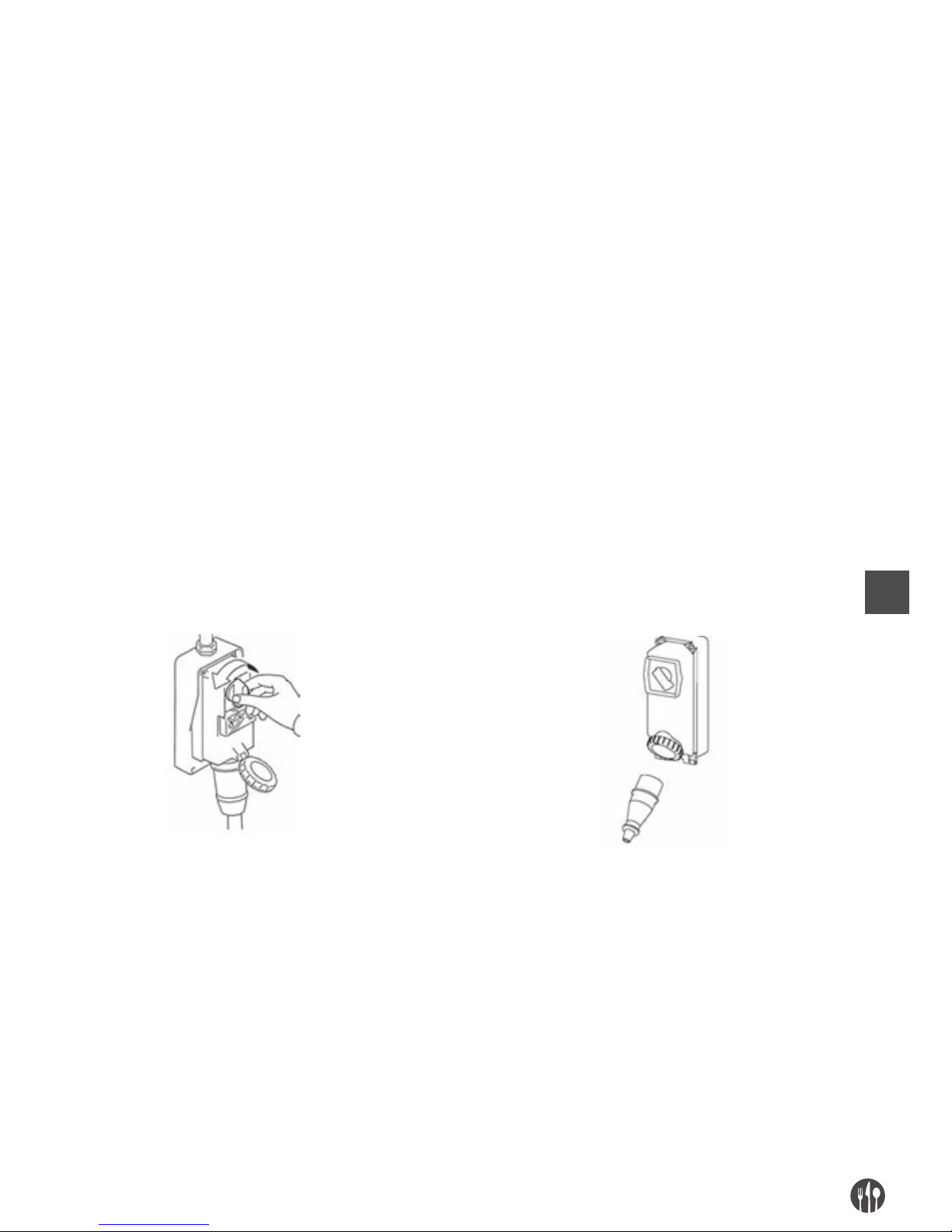
DE
33
CAP. 5. WARTUNG, FEHLERSUCHE UND REINIGUNG
ANFORDERUNGEN AN DAS WARTUNGSPERSONAL
Unter dem Begriff “Wartung“ ist nicht nur die regelmäßige Überprüfung des normalen Betriebs des
Geräts zu verstehen, sondern auch die Analyse und
die daraus folgenden Eingriffe im Bezug auf alle Ursachen, die aus irgendeinem Grund das Gerät außer
Betrieb setzen. Bei Tätigkeiten in den Bereichen
Wartung, Reinigung Ersetzung von Einzelteilen
und Fehlersuche, die durch den Anwender vorge-
nommen werden, sind diese Aufgaben unbedingt
erfahrenen und durch den Auftraggeber befugten
Fachpersonen anzuvertrauen.
Alle Tätigkeiten im Bezug auf Wartung, Reinigung
und Ersetzung von Einzelteilen ohne Ausnahme
sind unbedingt bei vollkommen still stehendem
Gerät und erst nach der Abtrennung von äußeren
Stromquellen auszuführen.
WARTUNGSVORSCHRIFTEN
ABNAHME DER ABSCHIRMUNGEN UND/ODER DER SCHUTZVORRICHTUNGEN
Bei einigen Eingriffen, die in diesem Kapitel erwähnt
wurden, sind einige feste Schutzvorrichtungen zu
entfernen.
Ihre Abnahme darf nur durch den Wartungstechniker
erfolgen.
Am Ende der Eingriffe sind diese Abschirmungen
wieder anzubringen und durch die vor dem Eingriff
angewandten Vorrichtungen in ihrer Originalposition
wieder zu befestigen.
Bevor er die feste Abschirmung entfernt und/oder ein Element ersetzt, hat der für die Wartung zuständige
Techniker die Maschine komplett auszuschalten, wie im Folgenden beschrieben.
ABTRENNEN VON ÄUßEREN STROMQUELLEN
Vor der Ausführung der Eingriffe im Bereich Wartung, Reinigung und Ersetzung von Teilen sind die äußeren Stromquellen abzutrennen und zu isolieren.
Die vor der Stromleitung des Geräts geschaltete
Schutzeinrichtung der elektrischen Anlage auf
„Null” schalten.
Haupt-Netztrennschalter deaktivieren und den
Stecker mit entsprechenden Hilfsmitteln abdecken
Page 34

DE
34
FEHLERSUCHE UND ENTSPERRUNG VON BEWEGLICHEN ELEMENTEN
Im Folgenden werden die Schritte angegeben für die Fehlersuche und Entsperrung von beweglichen
Elementen, die durch das Wartungspersonal auszuführen sind.
TYP MÖGLICHE URSACHE/N VORGEHEN UND ERGEBNISSE
Netzausfall Generelles Black Out Stromversorgungsgesellschaft anfragen.
Vorgeschaltete Sicherungen oder
Thermomagnetschalter haben
angesprochen
Nach Behebung der Ursachen, die zum
Ansprechen der Schutzeinrichtung
geführt haben, diese Vorrichtung zurück
stellen. Bei Anhalten des Problems
einen Elektriker beiziehen.
Betriebsunterbrechung Ansprechen der Schutzeinrichtung
im Inneren des Geräts
Einen Elektriker beiziehen: Nach Behebung
der Ursachen, die zum Ansprechen
der Schutzeinrichtung geführt haben, diese
Vorrichtung zurück stellen.
Bei Ansprechen der Sicherungen, diese mit
einer Sicherung gleichen Modells, gleicher
Eichung und Ansprechkurve ersetzen.
Anheben des Griffes
des Niederhalters
(grünes Led Blinklicht)
Beim Anheben des Niederhalters, die Maschine
ausschaltet sofort beim Einschalten des
Mikro-sicherheitsschalters. Den Niederhalter
niederdrücken so dass es nicht möglich ist, die
Finger in die Scherzone zu stecken.
Entfernung der oberen Bedeckung
(rotes Led Blinklicht)
Beim Entfernen der oberen Bedeckung,
die Maschine ausschaltet sofort beim
Einschalten des Mikro-sicherheitsschalters.
Die obere Bedeckung richtig legen
und diese mit dem geeigneten Knopf anziehen,
dann die Maschine einschalten.
Nicht identifizierbare Ursache/n Direkt die anerkannte Kundendienststelle
benachrichtigen
Das Gerät funktioniert
nicht: Die Scheiben
drehen sich nicht
oder führen keinen
sauberen Schnitt aus
Spannungslosigkeit
(alle Led Lichter ausgeschaltet)
Stromzufuhr überprüfen und wieder herstellen.
Apparate für Leistungsverteilung auf
„ON“ (alle Led Lichter ausgeschaltet)
Netz-Trennvorrichtung auf Position „ON“
schalten
Sicherungen haben angesprochen
oder Thermomagnetschalter
funktionieren nicht.
Angesprochene Sicherungen ersetzen lassen,
Thermomagnetschalter überprüfen.
Starttaste nicht betriebsfähig Betriebsfähigkeit der Taste „I“ überprüfen
und gegebenenfalls direkt die anerkannte
Kundendienststelle beiziehen.
Mikroschalter defekt Direkt die anerkannte Kundendienststelle
benachrichtigen
Schneidscheiben abgenutzt oder
beschädigt
Direkt die anerkannte Kundendienststelle
benachrichtigen
Langsamer Antriebsriemen
verursacht Lärm oder Knirschen
Direkt die anerkannte Kundendienststelle
benachrichtigen
Page 35

DE
35
AUßERORDENTLICHE WARTUNG
Für Eingriffe im Bereich außerordentliche Wartung
die infolge von Brüchen, Überholungen oder mechanischen oder elektrischen Störungen nötig sind (z.B.
die Spannung der Antriebsriemen etc…), ist direkt
die anerkannte Kundendienststelle anzufragen.
Die Anweisungen bezüglich der außerordentlichen
Wartung sind im vorliegenden Bedienungshandbuch nicht enthalten und sind ausdrücklich beim
Hersteller anzufordern.
REINIGUNG
Die Reinigung laufender Organe oder Elemente von
Hand ist untersagt.
Alle Reinigungseingriffe dürfen ausschließlich
durchgeführt werden, nachdem das Gerät komplett
von dem bearbeiteten Nahrungsmittel befreit und
von der äußeren Stromversorgungsquelle abgetrennt wurde.
Das Gerät, die elektrische Anlage und die Bestand-
teile auf dem Gerät niemals mit Wasser reinigen,
ebenso wenig mit einem Strahl, ungeachtet welcher Beschaffenheit oder welcher Menge auch immer; deshalb ohne „Kessel”, „Schlauch” oder
„Schwamm” reinigen. Niemals das Gerät direkt in
ein Spülbecken oder unter einen Wasserhahn stellen.
Die Hygienestufe des Geräts und dessen Zubehör
ist für die vorgesehene Anwendung 2 (zwei): Gerä-
te, die auf Grund einer hygienebezogenen Risikoana-
lyse den internationalen Anforderungen entsprechen, jedoch eine programmierte Zerlegung des
Geräts für die Reinigung erfordern.
HÄUFIGKEIT PERSONAL VORGANG
Am Ende jeder Arbeitsschicht und jedenfalls vor
der täglichen Benutzung
Operator Alle Oberflächen und Teile am Gerät, die mit Nahrungsmittel in Be-
rührung kommen, bzw. Nahrungsmittelbereiche (Innenfläche der
Einfüll- und Auswurföffnungen, Presser, Stopfer, Schnittbereich,
bewegliche und feste Scheiben, Deckel, feste Abschirmungen) und
die Spritzbereiche (Außenfläche des Geräts) sind wie unten angegeben zu reinigen und zu desinfizieren. Für die Demontage der
Schneideinheit siehe vorhergehende Beschreibungen.
• Die Oberflächen von eventuellen Nahrungsmittelrückständen
befreien (z.B. mit einem Plastikschaber);
• Alle Oberflächen des Nahrungsmittelbereichs und Spritzbe-
reichs mit einem feuchten weichen Tuch (nicht triefend) und in
warmem Wasser verdünntem Reinigungsmittel reinigen (auch
gewöhnliche Abwaschseife); Nicht einweichen. Spezifische, für
Stahl geeignete, flüssige und vor allem chlorfreie Mittel verwenden (keine Cremes oder Schleifpasten). Gegen Fett kann denaturierter Alkohol verwendet werden.
• Mit sauberem warmem Wasser spülen und anschließend alle
Oberflächen des Nahrungsmittelbereichs und Spritzbereichs
mit einem weichen, nicht faserigen Tuch abtrocknen.
• Alle Teile aus Edelstahl können auch im Geschirrspüler gereinigt werden.
• Die Neumontage ist nur bei Bedarf für eine neue Bearbeitung
durchzuführen; die Teile in einem weichen, nicht faserigen Tuch
eingewickelt aufbewahren
Page 36
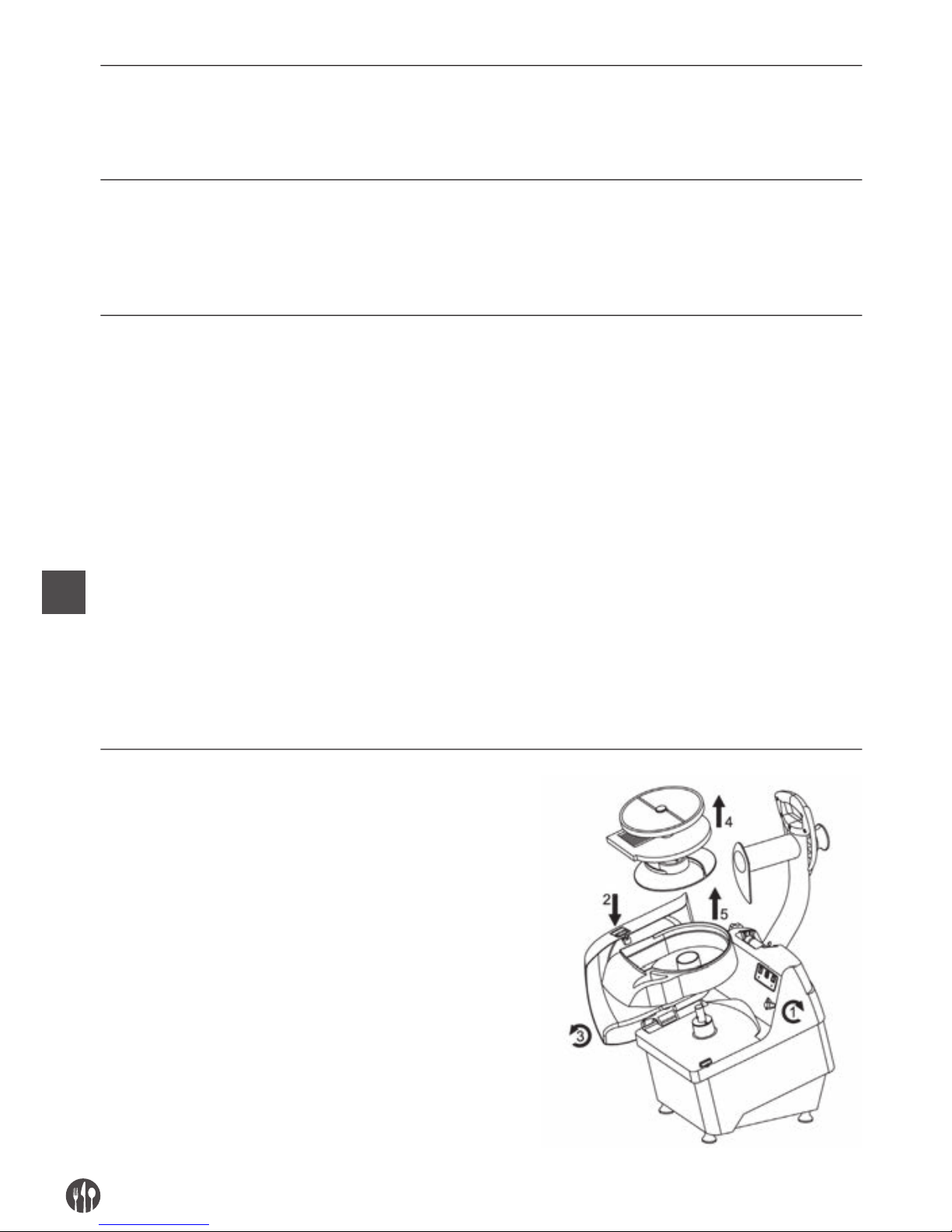
DE
36
LANGE BETRIEBSLOSIGKEIT
• Bei langer Betriebslosigkeit des Geräts ist auf allen Stahlober-
flächen (besonders jene aus Edelstahl) Vaselinöl mit einem Tuch
kräftig aufzutragen, damit diese Teile durch eine zusätzliche
Schicht geschützt werden.
VOR ODER WÄHREND DER REINIGUNG IST ES UNTERSAGT:
• auf bewegliche Elemente zuzugreifen, ohne dass zuvor überprüft
wurde, ob diese still stehen;
• auf bewegliche Elemente zuzugreifen ohne dass das Gerät garantiert sicher angehalten wurde (Netz-Trennvorrichtung auf
Position Null)
PRODUKTE, DIE NICHT BENUTZT WERDEN SOLLTEN:
• Druckluftstrahlen gegen Bereiche, in denen sich Mehl befindet
und generell gegen das Gerät;
• Dampfreinigungsgeräte;
• Reinigungsmittel, die CHLOR enthalten (auch verdünnt) oder aus
dessen Verbindungen bestehen, wie: Bleichlauge, Chlorwasserstoffsäure, Entstopfungsmittel, Reinigungsmittel für Marmor,
Entkalkungsmittel allgemein, etc … diese können die Beschaffenheit des Stahls angreifen und unwiderrufliche Flecken oder
Oxidation verursachen. Bereits Dämpfe der oben genannten Mittel können oxidieren und in einigen Fällen den Stahl anfressen;
• Metallplättchen, Bürsten oder Polierscheiben aus anderen Metallen oder Legierungen (z.B. gewöhnlicher Stahl, Alu, Messing,
etc…) oder Werkzeuge, die zuvor für die Reinigung anderer Metalle oder Legierungen benutzt wurden. Diese Mittel zerkratzen
die Oberfläche des Geräts.
• reibende Reinigungspulver;
• Benzin, Lösungsmittel oder entflammbare und/oder korrodierende Fluide;
• Silberreinigungsmittel.
ZERLEGEN / ANBAU FÜR DIE REINIGUNG
1. Den Sperrknopf (1) der oberen Bedeckung anziehen,
den Knopf (2) drücken und mit beiden Hände
die obere Bedeckung (3) durchdrehen
2. Die Schnittscheiben (Drehscheibe und
Festscheibe) und die Auswurfscheibe (4)
aus der Drehnabe herausnehmen,
die Kunststoffbox entfernen (5).
Page 37
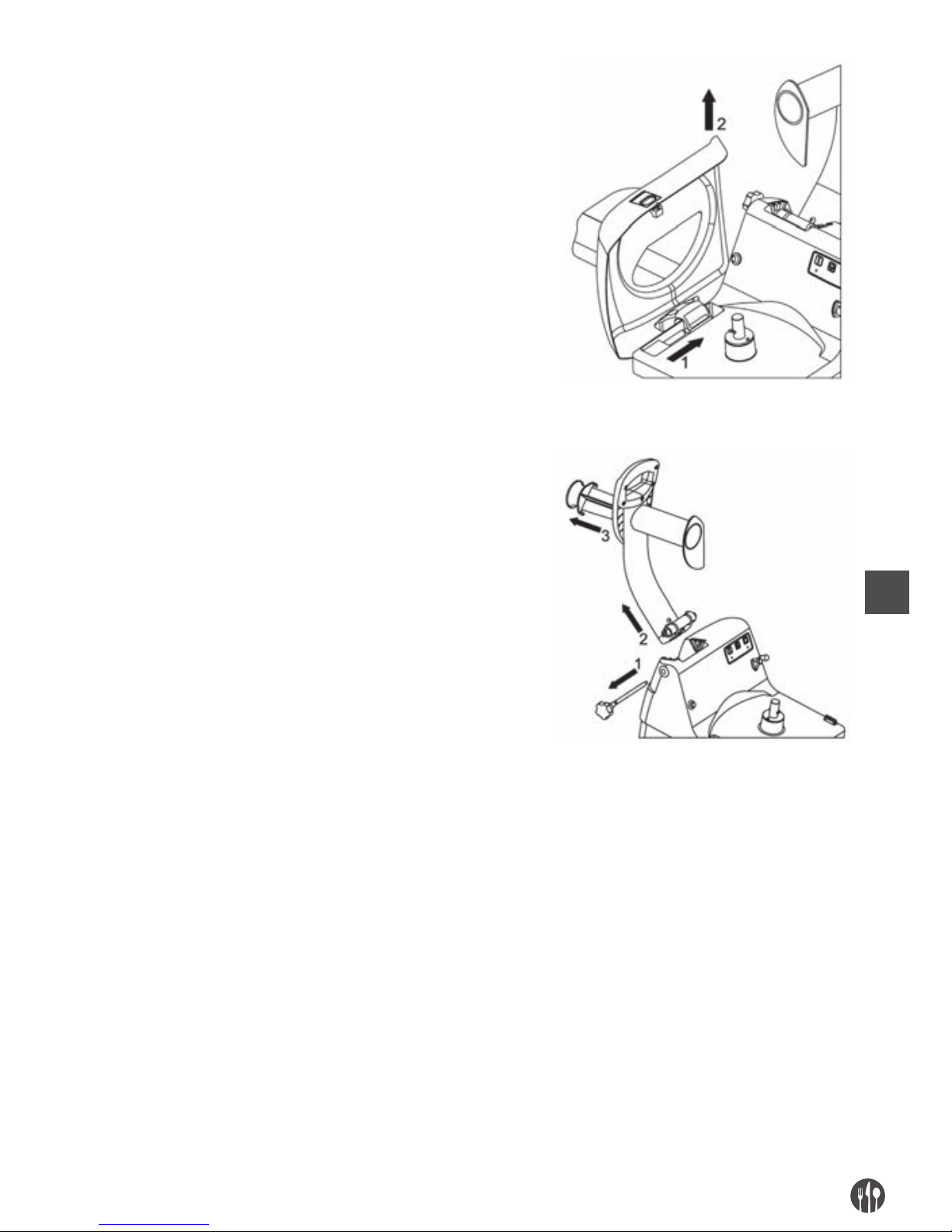
DE
37
3. Die obere Bedeckung entfernen (2) beim
Abziehen aus der Drehnabe (1)
4. Den Griff des Niederhalters am Ende legen.
5. Die Sicherheitsnabe (1) abziehen
6. Den Griff des Niederhalters (2) aus
seinem Sitz abkoppeln, beim Anheben
nach oben
7. Den Stampfer (3) drehen und danach
herausnehmen.
CAP. 6. ENTSORGUNG
Für den Fall, dass man entscheidet, die Maschine
nicht mehr zu benutzen, weil sie obsolet, kaputt oder
so abgenutzt ist, dass die Reparatur unwirtschaftlich ist, soll man diese außer Betrieb setzen und sie
wirkungslos und gefahrlos machen. Die Außerbetriebnahme muss spezialisiertem und ausgerüstetem Personal anvertraut werden.
Am Ende der Demontage müssen alle Identifikationsschilder und alle andere Dokumente zerstört
werden.
Die Maschine kann entsorgt werden ohne sie in
kleine Stücke zu zerbrechen, es genügt die Aggregate zu trennen, aus denen sie zusammengesetzt
ist, und diese zu verschrotten.
Diese entsorgen in Übereinstimmung mit den geltenden Gesetzen, beim Anwenden an Durchsetzungsstellen bzw. auf industrielle Verschrottung
oder Entsorgung spezialisierten Unternehmen, so
dass es die Trennung zwischen Kunststoff, Metall
und elektrische Bauelemente gibt, die zu getrennte
Müllsammlungen geschickt sein müssen.
Der Arbeitgeber muss Kenntnisse der in seinem eigenen Land geltenden Gesetze haben und sich verhal-
ten, um solche Gesetze zu folgen.
Page 38

DE
38
Es ist verboten, und dazu mit Sanktionen belegt, die Maschine und die elektrische Ausrüstung in die
Landschaft zu werfen.
Das auf die Maschine geschriebene Symbol der durchgestrichenen Mülltonne zeigt, dass das Produkt am
Ende der Betriebsdauer getrennt von dem anderen Abfall entsorgt werden muss.
Am Ende des Maschinenlebens muss der Benutzer damit die Maschine in geeignete Zentren für die getrennte Absammlung von elektronike und Elektrotechnische Abfällen.
CAP. 7. BAUMATERIAL
Je nach Betriebs- und Produktionsbedürfnissen kann das Gerät aus verschiedenen Materialtypologien
bestehen.
GRUPPE MATERIALTYPEN
Edelstahl Edelstahl Kunststoff für behandeltes
18/8 AISI 304 Nahrungsmittel Aluminium für
Nahrungsmittel
Gerätekörper •
Oberer abnehmbarer Deckel •
Einfüllöffnungen •
Auswurföffnung •
Bewegliche Scheiben • • •
Schneidelemente auf
den beweglichen Scheiben
•
Feste Scheiben • • •
Schneidelemente auf den festen
Scheiben
•
Auswurfscheibe •
Stopfer •
Presser •
Page 39

DE
39
Page 40

PL
40
SPIS TREŚCI
ROZDZ. 1. STRUKTURA INSTRUKCJI .......................................................... 41
ROZDZ. 2. OGÓLNE INFORMACJE I OPIS .................................................... 42
ROZDZ. 3. WSKAZÓWKI DOTYCZĄCE BEZPIECZEŃSTWA .......................... 45
ROZDZ. 4. TRANSPORT, URUCHOMIENIE I OBSŁUGA ................................ 47
ROZDZ. 5. KONSERWACJA, ROZWIĄZYWANIE PROBLEMÓW I CZYSZCZENIE
..
52
ROZDZ. 6. UTYLIZACJA ................................................................................ 56
ROZDZ. 7. MATERIAŁY, Z KTÓRYCH WYKONANO URZĄDZENIE ................. 57
Page 41

PL
41
ROZDZIAŁ 1. STRUKTURA INSTRUKCJI PRZEZNACZENIE INSTRUKCJI
ZNACZENIE INSTRUKCJI
Niniejsza instrukcja obsługi stanowi integralną część urządzenia
• Należy zachować ją na cały okres użytkowania
urządzenia.
• W przypadku zaprzestania korzystania z urządzenia musi być do niego dołączona.
• Oprócz ważnych uwag dla operatorów, instrukcja
zawiera schematy elektryczne niezbędne do konserwacji i napraw.
ZAKRES I CEL INSTRUKCJI
Niniejsza instrukcja zawiera wszelkie niezbędne informacje na temat używania urządzenia oraz wska-
zówki dotyczące bezpieczeństwa.
Instrukcja zawiera także wskazówki i ostrzeżenia,
umożliwiające poznanie zasady działania urządzenia
i zachowanie bezpieczeństwa. W przypadku wątpliwości należy skontaktować się z autoryzowanym
centrum serwisowym.
ODBIORCY
Niniejsza instrukcja obsługi, dostarczona w jednej
kopii wraz z urządzeniem, stanowi integralną część
urządzenia i przeznaczona jest dla operatorów i technikó
w uprawnionych do instalacji, używania i kon-
serwacji urządzenia.
Pracownicy odpowiedzialni za konserwację i serwisowanie, a także inni pracownicy użytkujący
urządzenie zobowiązani są zapoznać się z niniejszą
instrukcją i stosować się do zawartych w niej zale-
ceń.
ODPOWIEDZIALNOŚĆ
• W przypadku zniszczenia lub zagubienia niniejszej
instrukcji, można uzyskać jej kopię w autoryzo-
wanym centrum serwisowym.
• Niniejsza instrukcja odpowiada stanowi fabrycz-
nemu urządzenia, producent zastrzega sobie
prawo do zmian produkcyjnych oraz kolejnych instrukcji bez konieczności aktualizowania poprzednich
instrukcji, za wyjątkiem szczególnych przy-
padków związanych ze zdrowiem i bezpieczeństwe
m
użytkowników.
• Należy zwrócić szczególną uwagę na ryzyko
resztkowe związane z urządzeniem oraz przestrzeganie zaleceń przez operatorów.
• Producent odpowiada za urządzenie w pierwotnej
jego konfiguracji.
• Producent nie ponosi odpowiedzialności za szko-
dy wynikające z nieprawidłowego używania urządzenia oraz instrukcji ani za szkody spowodowane
nieprzestrzeganiem standardów, zaniedbaniem,
brakiem doświadczenia, brakiem rozwagi oraz
nieprzestrzeganiem przepisów przez pracodawcę, operatora lub konserwatora ani za wszelkie
inne możliwe szkody wynikłe z nieracjonalnego
lub niewłaściwego używania.
• Producent nie ponosi odpowiedzialności za kon-
sekwencje zastosowania części zamiennych innych niż oryginalne lub zamienników.
• Producent odpowiada wyłącznie za informacje
zawarte w instrukcji we włoskiej wersji językowej.
• Nieprzestrzeganie zaleceń zawartych w niniejszej
instrukcji powoduje nieważność gwarancji.
W miejscu użytkowania urządzenia i nadzorowania
prac z jego użyciem należy:
• Zapewnić odpowiednie środki bezpieczeństwa,
• Poinformować operatorów o istniejącym ryzyku
oraz o podstawowych metodach zapobiegania,
• Przygotować operatorów i dopilnować przestrzegania norm bezpieczeństwa oraz użytkowania zapewnionych środków bezpieczeństwa,
• Skierować do obsługi większą liczbę operatorów.
Page 42
PL
42
OZNACZENIA
Poniższa część zawiera objaśnienie symboli oraz definicji stosowanych w instrukcji.
ZAGROŻENIE
Oznacza zagrożenie dla operatora urządzenia lub osób pozostających w pobliżu oraz konieczność przeprowadzania czynności zgodnie z bieżącymi standardami zapobiegania wypadkom
i zaleceniami zawartymi w niniejszej instrukcji.
OSTRZEŻENIE
Wskazuje ostrzeżenie dotyczące ważnych informacji lub dalszych zaleceń lub zachowania
ostrożności podczas obsługi.
UWAGA
Oznacza konieczność zachowania ostrożności w celu uniknięcia uszkodzenia urządzenia.
ROZDZIAŁ 2. OGÓLNE INFORMACJE I OPIS PRZEZNACZENIE, CZĘŚCI
Szatkownica, zwana dalej urządzeniem, jest przeznaczona do krojenia w plastry, kostkę oraz tarcia owoców,
surowych warzyw (cukinie, marchew, seler, pomidory, itp) oraz innych warzyw o tej samej twardości.
Urządzenie składa się z silnika i obudowy (podstawa
urządzenia), w której wał silnika za pomocą odpowiednich pasów transmisyjnych połączony jest z narzędziem tnącym.
Składniki spożywcze można umieścić w urządzeniu
ręcznie:
1. przez znajdujący się w lewej górnej części urzą-
dzenia podajnik do krojenia w kostkę, szatkowania lub cięcia w paski; ręczne dociskanie uchwytu
powoduje dociskanie zawartości urządzenia do
strefy tnącej. Urządzenie należy napełniać umiarkowaną ilością składników, aby uniknąć sytuacji,
w której urządzenie nie uruchomi się ze względu
na zadziałanie mikroprzełącznika umieszczonego
w bloku docisku;
2. przez znajdujący się w prawej górnej części urzą-
dzenia podajnik do krojenia; ręczne dociskanie
kołkiem dociskowym wciskanym do szyjki urządzenia powoduje dociśnięcie zawartości urządzenia do strefy tnącej. Kołek dociskowy jest wykonany z tworzywa sztucznego przeznaczonego do
kontaktu z żywnością.
Otwór podajnika do cięcia w kostkę oraz otwór podajnika do krojenia znajdują się w pokrywie obu-
dowy zablokowanej na urządzeniu za pomocą odpo-
wiedniego pokrętła; na urządzeniu znajduje się
mikroprzełącznik zabezpieczający, który wskazuje
prawidłowe położenie pokrywy.
Strefa tnąca urządzenia obejmuje jego część wewnętrzną, w której ręcznie umieszcza się obrotowe
tarcze tnące połączone za pomocą złącza bagneto-
wego z wałem silnika oraz innymi tarczami nieruchomymi:
• tarcze obrotowe do cięcia w plastry i tarcia;
• tarcze obrotowe do cięcia w plastry;
• tarcze obrotowe do cięcia w słupki ;
• tarcze nieruchome do krojenia w kostkę;
• tarcze nieruchome do cięcia w słupki (na frytki);
• obrotowa tarcza wyrzucająca (ewakuacyjna)
UWAGA: nie wszystkie rodzaje tarcz są w standardowym wyposażeniu szatkownicy!
W dolnej przedniej części urządzenia znajduje się
otwór wyładowczy, do którego odprowadzany jest
pokrojony produkt.
Page 43
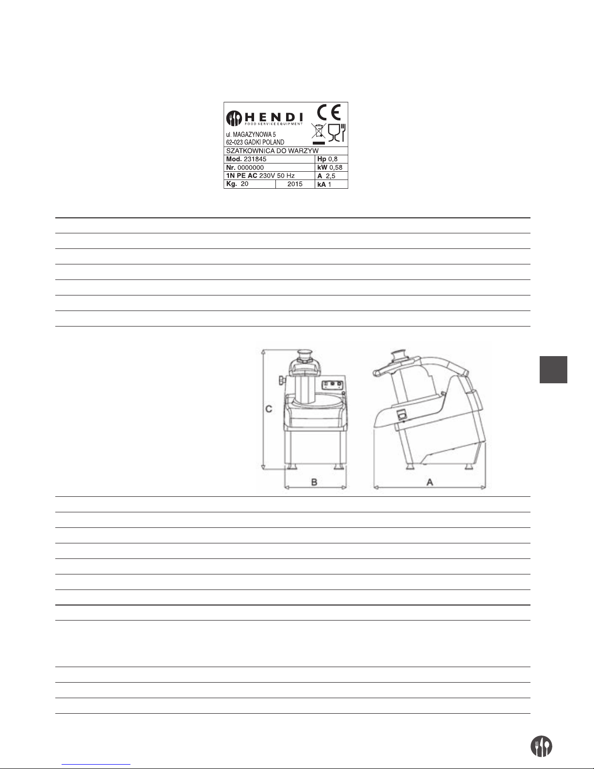
PL
43
Wszelkie materiały mające bezpośredni kontakt z
żywnością spełniają odpowiednie standardy higieny.
Zgodnie z wymaganiami funkcjonalnymi i produkcyjnymi, urządzenie może być użytkowane z różnymi
częściami opcjonalnymi.
Urządzenie dostarczane jest z tabliczką znamionową zawierającą następujące dane:
DANE TECHNICZNE
Moc silnika (W)/(KM) 580 W/0,80 KM
Wymiar wewnętrzny podajnika do krojenia w kostkę (mm) 180 x 80
Długość szyjki podajnika do krojenia w plasterki (mm) 150
Wymiar wewnętrzny szyjki do krojenia w plasterki (mm) 57
Wysokość szyjki podajnika do cięcia (mm) 190
Wydajność (kg/h) 250-450
Masa (kg) 21,5
Wymiary: A x B x C (mm) 490 x 280 x 530
Poziom hałasu Mniej niż 70 dBA
Rodzaj prądu - częstotliwość 50 Hz
Napięcie 230 V
Napięcie nominalne 230 V
Napięcie obwodów pomocniczych AC 24 V - DC 24 V
Masa i zero TT i TN
Stopień szczelności IPX3
Miejsce eksploatacji Wnętrze
Umiejscowienie urządzenia Gastronomiczny stół roboczy o wysokości 900/1100 mm od podłogi,
o odpowiednim udźwigu, z wolną przestrzenią wokół wynoszącą
co najmniej 800 mm
Maksymalna temperatura otoczenia +40°C
Wymagane oświetlenie minimalne 500 luksów
Zgodność z dyrektywami 2006/42/WE, 2006/95/WE z późniejszymi zmianami, rozp. 1935/2004
Page 44
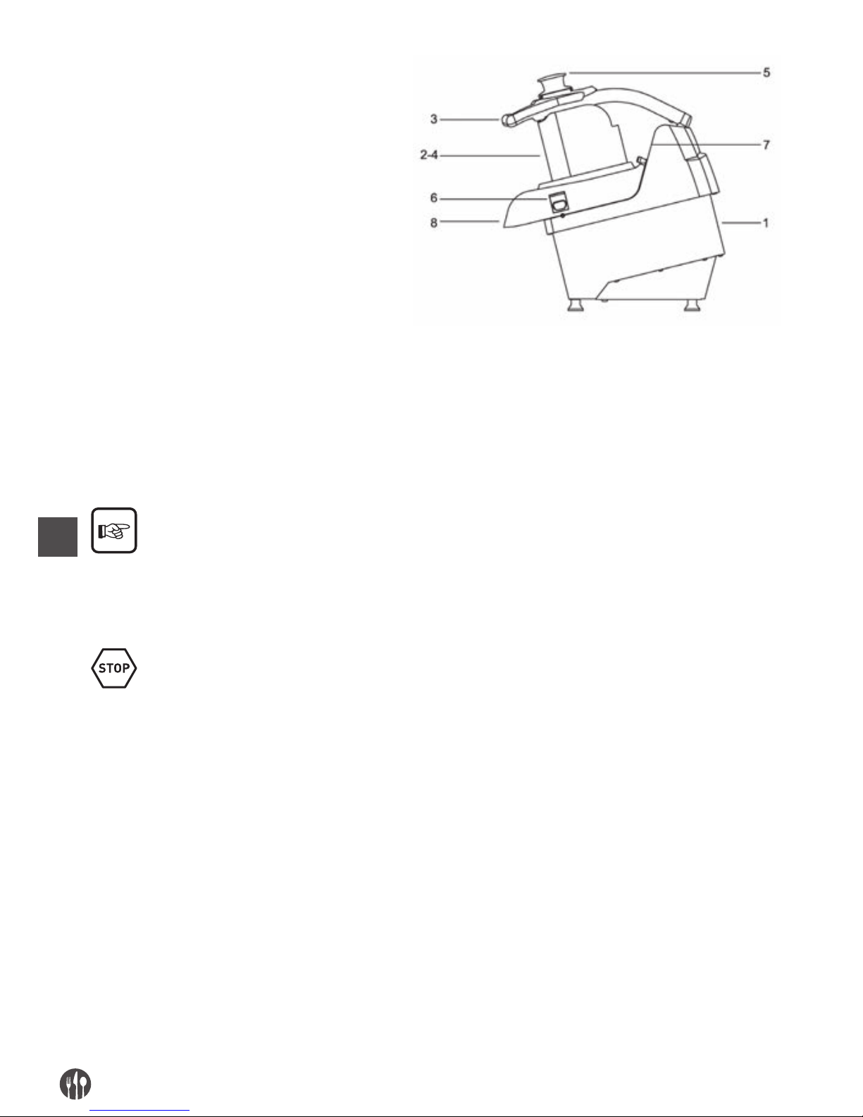
PL
44
1. korpus
2. podajnik do plastrów
3. uchwyt dociskowy
4. podajnik do krojenia w kostkę lub w paski
5. kołek dociskowy
6. pokrętło blokady pokrywy
7. panel sterowania
8. otwór wyładowczy
NORMALNA EKSPLOATACJA, NIEPRAWIDŁOWE LUB NIEDOZWOLONA EKSPLOATACJA
Urządzenie opisane w niniejszej instrukcji przeznaczone jest do obsługi wyłącznie przez wyszkolone-
go operatora, znającego ryzyko resztkowe, z zachowaniem środków bezpieczeństwa.
Operator powinien spełniać wymogi ustawowe do-
tyczące wieku oraz przejść odpowiednie przeszkolenie techniczne w zakresie prawidłowej obsługi
urządzenia pod nadzorem wyszkolonego pracownika.
Przy NORMALNEJ, PRZEWIDYWALNEJ EKSPLOATACJI urządzenie może być wykorzystywane tylko
do krojenia w kostkę i tarcia owoców, surowych wa-
rzyw wszystkich znanych rodzajów, cukinii, marchwi, selera, ziemniaków, papryki, pomidorów, itp.
oraz innych o tej samej twardości.
Urządzenia nie wolno używać W SPOSÓB NIEWŁAŚCIWY, w szczególności:
• nie należy używać go w warunkach domowych,
• nie należy używać go przy parametrach innych niż
wyszczególnione w tabeli danych technicznych,
• z końcówkami innymi niż wskazane w niniejszej
instrukcji – w takich przypadkach producent zrzeka się odpowiedzialności,
• użytkownik ponosi odpowiedzialność za uszko-
dzenia wynikłe z nieprzestrzegania warunków roboczych określonych w specyfikacji technicznej
i potwierdzeniu zamówienia.
• produkty spożywcze umieszczać w urządzeniu
suche, nie zaś wilgotne lub nieodsączone,
• nie ingerować w produkt, nie uszkadzać go celowo, nie usuwać ani zakrywać etykiet.
Urządzenia nie wolno eksploatować W SPOSÓB NIEWŁAŚCIWY lub NIEDOZWOLONY, ponieważ może doprowadzić to do obrażeń operatora, w szczególności:
• zabrania się przemieszczania urządzenia, gdy
jest podłączone do zasilania elektrycznego;
• zabrania się ciągnięcia za przewód zasilający ani
za samo urządzenie, aby odłączyć wtyczkę od
gniazdka,
• nie wolno obciążać urządzenia ani przewodu zasilającego,
• nie wolno kłaść przewodu zasilania na ostro za-
kończonych przedmiotach, ani na przedmiotach
emitujących ciepło;
• nie wolno używać urządzenia z uszkodzonym
przewodem zasilania lub przełącznikami;
• nie wolno pozostawiać wyłączonego urządzenia
z podłączonym do sieci przewodem zasilania,
Page 45
PL
45
• nie wolno pozostawiać urządzenia ze wsadem
bez nadzoru;
• nie wolno wkładać żadnych przedmiotów do
szczeliny wentylacyjnej silnika;
• nie wolno umieszczać urządzenia nad innymi
przedmiotami używanymi do obróbki żywności
znajdującymi się na blacie na wysokości 900 –
1100 mm od posadzki;
• nie wolno wkładać żadnych przedmiotów pod
podstawę urządzenia ani umieszczać tkanin albo
innych przedmiotów pomiędzy blatem a stopkami
urządzenia,
• nie wolno używać do czyszczenia substancji ła-
twopalnych, żrących ani szkodliwych,
• nie wolno zanurzać urządzenia w wodzie ani innych cieczach;
• z urządzenia korzystać mogą wyłącznie upraw-
nieni pracownicy, w odzieży przeznaczonego do
tego celu,
• nie wolno wkładać do strefy tnącej oraz otworu
wyładowczego rąk ani innych części ciała w celu
wyjęcia pokrojonych produktów spożywczych;
• nie wolno wkładać do otworu wyładowczego żad-
nych przedmiotów, np. ostrza noża, itp.,
• nie wolno zdejmować pokrywy zamocowanej na
urządzeniu podczas pracy urządzenia lub w do-
wolnym momencie od napełnienia urządzenia
żywnością do poszatkowania,
• nie wolno podczas pracy urządzenia próbować
otwierać ani podnosić pokrywy, uderzać ani
przechylać urządzenia, otwierać ani zdejmować
obudowy ochronnej znajdującej się na spodzie,
• nie wolno obluzowywać pokrętła blokującego
pokrywę urządzenia podczas pracy urządzenia,
ani przed upływem 5 sekund od naciśnięcia wyłącznika urządzenia,
• nie wolno uruchamiać urządzenia z nieprawidło-
wo zablokowanymi lub zdjętymi osłonami części
ruchomych i stałych;
• nie wolno częściowo demontować zabezpieczeń
ani ignorować ostrzeżeń bezpieczeństwa;
• nie wolno używać urządzenia, jeśli użytkownik nie
podjął wszelkich środków ostrożności chronią-
cych przed ryzykiem resztkowym;
• nie wolno palić ani używać urządzeń z płomie-
niem ani posługiwać się materiałami łatwopalnymi, o ile nie zostały podjęte środki bezpieczeństwa;
• nie wolno włączać ani konfigurować elementów
sterowania ani blokad, pokręteł itp. podczas
użytkowania urządzenia lub w przypadku braku
uprawnień.
Użytkownik ponosi odpowiedzialność za uszkodzenia wynikające z nieprzestrzegania określonych wymogów obsługi. W przypadku wątpliwości należy skontaktować się z autoryzowanym centrum serwisowym.
ROZDZ. 3. WSKAZÓWKI DOTYCZĄCE BEZPIECZEŃSTWA
WPROWADZENIE
Brak standardów i niestosowanie się do procedur
bezpieczeństwa może stanowić zagrożenie.
Korzystanie z urządzenia oznacza zobowiązanie
użytkownika do przestrzegania:
• wszelkich zasad dotyczących uwolnienia do środowiska i używania zgodnie z obowiązującym pra-
wem lub normami, ze szczególnym uwzględnieniem
wytycznych dotyczących używania i podłączania
urządzenia,
• wszelkich dalszych instrukcji oraz ostrzeżeń stanowiących część dokumentacji technicznej/rysunkowej urządzenia.
Page 46
PL
46
O ile nie określono inaczej, pracownicy wykonujący
podłączenie, czynności konserwacyjne, demontaż i
naprawy muszą być przeszkoleni w zakresie bez-
pieczeństwa i świadomi ryzyka resztkowego, posiadający w zakresie bezpieczeństwa te same kompetencje, co pracownicy odpowiedzialni za konserwację.
OTOCZENIE ORAZ MIEJSCE EKSPLOATACJI
Otoczenie robocze musi spełniać wymogi dyrektywy
89/654/EWG. W obszarze roboczym nie mogą znajdować się obce przedmioty. Pracodawca, zgodnie z
dyrektywą 89/391/EWG w sprawie wprowadzenia
środków w celu poprawy bezpieczeństwa i zdrowia
pracowników w miejscu pracy, zobowiązany jest wyeliminować lub zminimalizować wskazane ryzyko
resztkowe, zgodnie z niniejszą instrukcją.
OSTRZEŻENIE DOTYCZĄCE RYZYKA RESZTKOWEGO
RYZYKO RESZTKOWE WYNIKAJĄCE Z USUNIĘCIA STAŁYCH I RUCHOMYCH ZABEZPIECZEŃ, NAPRAW
USZKODZONYCH/ZUŻYTYCH CZĘŚCI
W żadnych okolicznościach operatorowi nie wolno
dokonywać prób otwarcia lub usunięcia stałego zabezpieczenia ani ingerencji w zabezpieczenie.
W trakcie konserwacji, zmiany urządzeń i czyszczenia oraz podczas wszelkich prac wykonywanych
ręcznie, które wiążą się z wprowadzaniem rąk do
niebezpiecznych obszarów urządzenia, występuje
ryzyko resztkowe, wynikające przede wszystkim z:
• uderzenia częścią urządzenia,
• obtarcia o szorstkie elementy urządzenia,
• ukłucia ostrymi elementami,
• skaleczenia ostrymi elementami.
Ponadto podczas czynności napełniania z podnie-
sionym dociskiem ryzyko resztkowe związane jest
przede wszystkim ze skaleczeniami ostrymi częściami.
Podczas czynności mycia lub usuwania zablokowa-
nych składników z ostrza, ryzyko resztkowe związane jest przede wszystkim ze skaleczeniami ostry-
mi częściami.
Operator i konserwator muszą być przeszkoleni
w zakresie obsługi ręcznej przy otwartych zabezpieczeniach, znać związane z tym ryzyko i być upo-
ważnionym przed osobę odpowiedzialną, a także
stosować środki ochrony indywidualnej, np. pięcio-
palczaste rękawice ochronne. Wszelkie czynności
związane z tarczami należy przeprowadzać przy
ostrzach zwróconych do dołu.
ZABEZPIECZENIA URZĄDZENIA
Nie wolno demontować zabezpieczeń urządzenia.
Jeżeli niezbędne jest zdemontowanie ich w celu
przeprowadzenia nadzwyczajnych czynności konserwacyjnych, należy zastosować wszelkie środki
ostrożności w celu ograniczenia do minimum niebezpieczeństwa, które może z tego wyniknąć.
Zabezpieczenia należy zamontować z powrotem niezwłocznie po zakończeniu czynności, które wymagały ich demontażu.
Wszystkie zabezpieczenia urządzenia, zarówno mechaniczne, jak i elektryczne należy utrzymywać w
stanie najwyższej sprawności.
Urządzenia transmisyjne są całkowicie odizolowane przez stałe zabezpieczenia, które uniemożliwiają
dostęp do któregokolwiek z łańcuchów napędowych.
Do wszystkich funkcji zabezpieczeń, w tym do systemów sterowania i kontrolnych wykorzystano technologie o sprawdzonej skuteczności.
Page 47
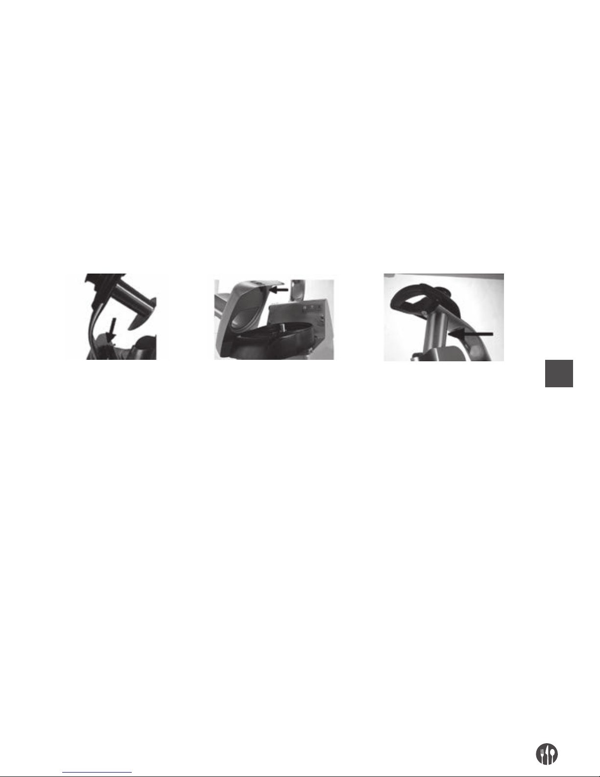
PL
47
GRUPA NARZĘDZI:
1. Ze względu na sposób użycia urządzenia oraz jego
przeznaczenie, ruchome części są odizolowane
od osłon stałych i ruchomych oraz urządzeń zabezpieczających i umiejscowione w pewnej odległości od punktów dostępu do urządzenia, aby
miejsca niebezpieczne były niedostępne;
2. zespół uchwytu i docisku jest wyposażony w mikroprzełącznik, który zatrzymuje obracające się
narzędzia, gdy dostęp do nich jest możliwy przez
podajnik;
3. Podajnik do krojenia ma odpowiednią długość -
narzędzia znajdują się w takiej odległości od
punktów dostępu, żeby były niedostępne;
4. na pokrywie górnej części urządzenia znajduje się
mikroprzełącznik, który zatrzymuje obracające
się narzędzia, gdy dostęp do nich jest możliwy
przez strefę podajnika;
5. w strefie wyładowczej odprowadzanie produktu
odbywa się w taki sposób, że dosięgnięcie ostrych
elementów jest niemożliwe z powodu kształtu poszczególnych tarcz wyrzucających oraz tarcz ruchomych;
Uchwyt docisku
z mikroprzełącznikiem
Zdemontowana pokrywa górna
z mikroprzełącznikiem
Otwór podajnika do krojenia
z osłoną stałą
ROZDZ. 4. TRANSPORT, URUCHOMIENIE I OBSŁUGA
MIEJSCE ROBOCZE I ZADANIA OPERATORA
Urządzenie opisane w niniejszej instrukcji przeznaczone jest do obsługi przez wyszkolonego operatora,
znającego ryzyko resztkowe, z zachowaniem środków bezpieczeństwa.
Normalną strefą roboczą operatora jest:
1. Strefa boczna urządzenia w pobliżu otworu podajnika (zdefiniowana strefa podawania) w normalnych warunkach roboczych przy ręcznym załadunku produktów spożywczych oraz podczas
korzystania z kołka dociskowego do przesuwania
produktów spożywczych przez szyjkę urządzenia
z osłonami stałymi i ruchomymi w pozycji za-
mkniętej i zablokowanej;
2. Strefa przednia urządzenia w pobliżu podajnika
produktów spożywczych w normalnych warunkach roboczych podczas ręcznego wyjmowania
produktów spożywczych z odpowiedniego pojemnika, z osłonami stałymi i ruchomymi w pozycji
zamkniętej i zablokowanej
CZYNNOŚCI PRZYGOTOWAWCZE
STABILNOŚĆ
Konstrukcja urządzenia w przewidywalnych warunkach roboczych, z uwzględnieniem warunków klimatycznych zapewnia stabilność podczas eksploatacji bez ryzyka nieszczelności, upadku lub
przypadkowego przemieszczania się.
Konstrukcja urządzenia zapewnia jego stabilność w
warunkach roboczych przy prawidłowym umiejscowieniu bez konieczności mocowania go do blatu ro-
boczego.
Stopki znajdujące się pod podstawą należy umieścić
na solidnej, jednorodnej i wypoziomowanej powierzchni.
Page 48
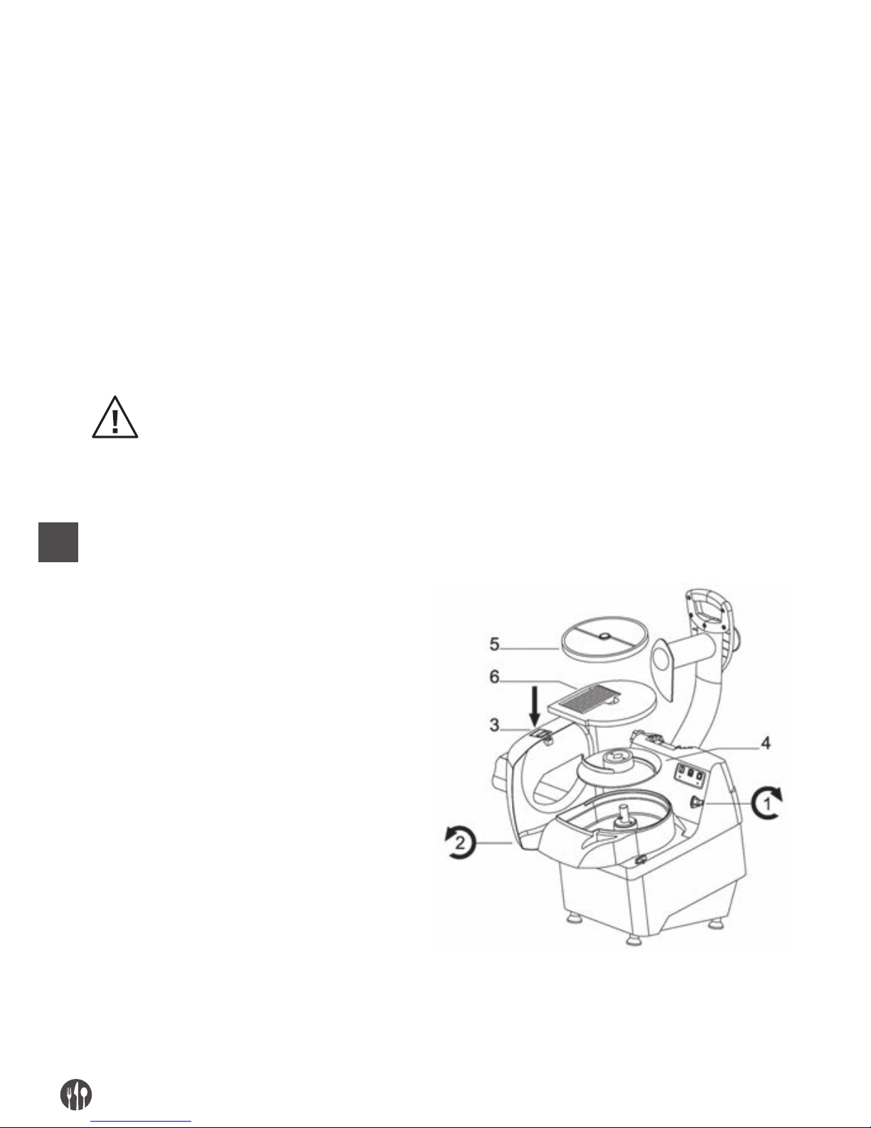
PL
48
ZASILANIE ELEKTRYCZNE
Połączenie elektryczne należy wykonać zgodnie z przepisami prawa obowiązującymi w kraju eksploatacji
urządzenia.
Zasilanie elektryczne musi być zgodne z następującymi zaleceniami technicznymi:
1. zasilanie elektryczne musi zawsze być typu i na-
tężenia zgodnego z danymi technicznymi podanymi na tabliczce znamionowej urządzenia. Użycie
zbyt wysokiego napięcia może nieodwracalnie
uszkodzić niektóre podzespoły,
2. należy przewidzieć wyłącznik różnicowo-prądo-
wy sprzężony z obwodem zabezpieczającym,
zgodny z przepisami oraz rozporządzeniami obowiązującymi w kraju eksploatacji urządzenia;
3. przewód zasilania elektrycznego na zewnątrz
obudowy urządzenia należy poprowadzić w odpo-
wiednio przygotowanych i zabezpieczonych miejscach;
4. o ile jest dostępny, przewód zerowy (N) podłączyć
przed zasileniem urządzenia, ponieważ należy zagwarantować jego ciągłość (podłączenie i sprawność);
5. przed zasileniem urządzenia należy zapewnić ciągłość zabezpieczenia (podłączone i sprawne) obwodem ekwipotencjalnym przez podłączenie żółto-zielonego przewodu.
MONTAŻ/DEMONTAŻ
Montaż/demontaż części urządzenia należy przeprowadzać przy wyłączonym urządzeniu, odłączonym od
zasilania lub przy wyłączonym urządzeniu zasilającym.
Zespół narzędzi urządzenia pracuje w różnych fazach.
1. Obrócić pokrętło blokady (1) pokrywy górnej (2),
nacisnąć przycisk (3) i oburącz obrócić
pokrywę górną (2)
2. Na piastę obrotową nałożyć najpierw tarczę
wyrzucającą (4), sprawdzając, czy mocowania
na piaście pasują do otworów w tarczy;
3. W przypadku gdy zadanie wymaga użycia tylko
jednej tarczy, założyć tarczę obrotową
na piastę (5) nad tarczą wyrzucającą (4)
4. W przypadku gdy zadanie wymaga jednoczesnego
użycia dwóch tarcz, założyć kolejno na piastę
obrotową następujące elementy:
• Tarcza wyrzucająca (4)
• Tarcza nieruchoma (6)
• Tarcza obrotowa (5)
5. Założyć z powrotem pokrywę górną (2),
obracając ją.
6. Dokręcić pokrętło blokady (1), obracając je
w lewo.
Page 49
PL
49
Po umieszczeniu tarcz zgodnie z wymogami roboczymi sprawdzić ich zaczepy bagnetowe na piaście obrotowej.
Tarcza wyrzucająca MUSI BYĆ ZAWSZE zainstalowana, aby tarcze tnące mogły zostać zamontowane pra-
widłowej pozycji.
Czynności demontażu należy przeprowadzać wykonując etapy montażu w odwróconej kolejności.
OBROTY TARCZ TNĄCYCH
Poniższe czynności może wykonać wyłącznie konserwator (pracownik posiadający odpowiednią wie-
dzę w zakresie elektryki urządzeń przemysłowych).
W przypadku urządzeń zasilanych napięciem trójfazowym (3 PE AC 400 V 50 Hz), nacisnąć przycisk
podtrzymywania czynności „
” i przez otwór po-
dajnika do krojenia sprawdzić, czy kierunek obrotu
tarcz jest prawidłowy (w lewo) wskazanym strzałką
umieszczoną na pokrywie urządzenia.
Jeżeli kierunek obrotu jest odwrotny (w prawo),
wyłączyć urządzenie, wyjmując wtyczkę z gniazda,
rozmontować urządzenie, odłączyć dwa przewody
fazowe i zamienić je miejscami.
OPIS DZIAŁANIA
Przyciski sterujące urządzenia zaprojektowano
i wykonano tak, aby zapewnić ich niezawodność i odporność na normalne użytkowanie oraz wpływ czyn-
ników zewnętrznych. Ponadto, są one wyraźnie widoczne
, łatwe do odnalezienia i odpowiednio oznaczone.
Poniżej przedstawiono główne elementy sterowania:
TYP/KOLOR OPIS
Przycisk/czarny Przycisk „O ” - wyłącznik urządzenia (STOP)
Przycisk/biały Przycisk „I” - włącznik urządzenia
Przycisk / biały Przycisk „ ” - przycisk uruchamiający urządzenie i podtrzymujący czynność
SYGNAŁY ŚWIETLNE
TYP/KOLOR OPIS
Świecąca stałym światłem
czerwona dioda LED
Uruchomienie urządzenia z zamkniętą pokrywą górną i obniżonym dociskiem
Migająca czerwona dioda LED Uruchomienie urządzenia z otwartą pokrywą górną
Świecąca stałym światłem
zielona dioda LED
Uruchomienie pracującego urządzenia
Migająca zielona dioda LED Uruchomienie urządzenia z wciśniętym przyciskiem uruchomienia i dociskiem
obniżonym do położenia uruchomienia urządzenia (świecąca ciągłym światłem
zielona dioda LED)
Page 50

PL
50
URUCHOMIENIE
Impuls uruchamiający urządzenie można wywołać
jedynie przez celowe użycie przycisku sterującego
przeznaczonego do tego celu: biały przycisk oznaczony symbolem „I” uruchamiający urządzenie.
STOP
Aby zatrzymać urządzenie, należy nacisnąć czarny
przycisk „O”. W przypadku tymczasowego lub dłuż-
szego wyłączenia, przed ponownym uruchomie-
niem urządzenia należy opróżnić urządzenie z produktów spożywczych: należy postępować według
wskazówek demontażu zespołu do mielenia.
URUCHAMIANIE PODTRZYMYWANEJ CZYNNOŚCI
Uruchomienie podtrzymywanej czynności można
wywołać jedynie przez celowe użycie przycisku
sterującego przeznaczonego do tego celu: biały
przycisk oznaczony symbolem „
” uruchamiający
urządzenie. Po zwolnieniu przycisku urządzenie jest
wyłączane.
BRAK ZASILANIA
W przypadku przerw w dostawie napięcia lub odłączenia urządzenia od sieci, należy ponownie urucho-
mić urządzenie po wznowieniu zasilania lub podłą-
czeniu do sieci.
OTWIERANIE DOCISKU
Po zdjęciu nacisku na uchwyt urządzenie natychmiast się zatrzymuje na skutek uruchomienia mikroprzełącznika. Urządzenie można ponownie uru-
chomić dopiero po obniżeniu docisku w położenie,
które uniemożliwia włożenie palców do strefy tnącej.
DEMONTAŻ POKRYWY URZĄDZENIA
Poluzowanie pokrętła blokady oraz ręczne zdjęcie
pokrywy powoduje natychmiastowe zatrzymanie
urządzenia na skutek uruchomienia mikroprzełącznika. Urządzenie można uruchomić ponownie dopie-
ro po założeniu pokrywy urządzenia i zablokowaniu
jej właściwym pokrętłem oraz włączeniu funkcji
uruchomienia.
KONTROLA PRZED URUCHOMIENIEM URZĄDZENIA
KONTROLA/SPRAWDZENIE ELEMENT I PORÓWNANIE
Należy sprawdzić:
• Czy w otworze podajnika
oraz otworze wyładowczym,
w strefie wyrzucania
produktu nie znajdują się
żadne ciała obce
Kontrola wzrokowa wskazanych części pod kątem obecności ciał obcych, np.
narzędzi, części odzieży itp. innych niż żywność.
W razie ich obecności należy je usunąć.
Sprawdzić czystość:
• części wewnętrznych
urządzenia
• strefy tnącej, tarcz,
wewnętrznej części pokrywy
urządzenia, otworu
wyładowczego
• docisku i kołka dociskowego
• zewnętrznej części
urządzenia
Należy sprawdzić czystość powierzchni wszystkich określonych części.
W celu przeprowadzenia kontroli wzrokowej wewnętrznych części strefy tnącej,
zdjąć pokrywę górną.
W przypadku obecności pleśni lub innego rodzaju zabrudzeń, należy przeprowadzić czyszczenie zgodnie ze wskazówkami zawartymi w rozdziale 5.
Page 51

PL
51
Sprawdzić stan:
• stałych zabezpieczeń
• zamknięcia pokrywy górnej
• otworów podajnika i
wyładunku docisku
• korpusu urządzenia
Wszystkie zabezpieczenia stałe itp. muszą być w odpowiednim stanie technicznym. Wykonać kontrolę wzrokową wskazanych części, aby sprawdzić stan ich
powierzchni. Części należy wymienić w przypadku objawów zużycia lub awarii
(patrz: autoryzowane centrum serwisowe).
Sprawdzić działanie:
• elementów systemu
sterowania/zabezpieczeń
• zabezpieczeń.
Wszystkie zabezpieczenia itp. muszą być w odpowiednim stanie technicznym.
Sprawdzić bezpośrednio elementy sterowania żądanymi funkcjami. Włączniki
i wszelkie części należy wymienić w przypadku objawów zużycia lub awarii
(patrz: autoryzowane centrum serwisowe).
Sprawdzić, czy nie występują:
• nietypowe odgłosy po
uruchomieniu
W trakcie kontroli działania zabezpieczeń, jeśli wystąpią nietypowe odgłosy,
wynikające np. z zakleszczenia składników lub uszkodzeń mechanicznych, należy
natychmiast wyłączyć urządzenie i przeprowadzić czynności
W przypadku napraw lub wymiany uszkodzonych
części należy przeprowadzić czynności konser-
wacyjne. Uszkodzone lub zużyte części należy wymienić na oryginalne części producenta lub zamien-
niki o tej samej jakości, parametrach bezpiec zeństwa
i danych technicznych. Aby uzyskać informacje na
temat części, należy skontaktować się z autoryzowanym centrum serwisowym.
OBSŁUGA
Operator zobowiązany jest obsługiwać urządzenie zgodnie z poniższymi instrukcjami:
• Po uzyskaniu pozytywnego wyniku przeprowadzonych kontroli przed uruchomieniem,
• Po uzyskaniu pozytywnych wyników kontroli zasilania,
• Po prawidłowym podłączeniu do sieci,
• Po uzyskaniu pozytywnych wyników kontroli montażu (kontrola położenia tarcz, itp.)
• Po uzyskaniu pozytywnego wyniku kontroli kierunku obrotu tarcz,
• Po uzyskaniu pozytywnych wyników kontroli
przed uruchomieniem,
• Po uzyskaniu pozytywnych wyników kontroli zabezpieczeń,
• Założyć górną pokrywę urządzenia i dokręcić pokrętło blokady;
• Ustawić z przodu urządzenia pod otworem wyładowczym naczynie na przygotowany produkt spo-
żywczy;
• Stanąć po lewej stronie urządzenia i nacisnąć
przycisk uruchamiający urządzenie „I”,
• Ręcznie napełnić urządzenie produktem spożywczym przez podajnik, zgodnie z wymogami roboczymi i dopchnąć w dół/w stronę strefy tnącej,
powoli obniżając uchwyt docisku lub korzystając z
kołka dociskowego, wywierać lekki nacisk, aby
uzyskać lepszy efekt bez zbytniego obciążania
części transmisyjnych. Gdy docisk lub kołek dociskowy dotrą do końca zakresu ruchu, podnieść je
i powtórzyć powyższe czynności, kontynuując aż
do zakończenia cyklu roboczego,
• Po zakończeniu wprowadzania żywności lub gdy z
obszaru wyładowczego przestanie być wyrzucany
produkt zatrzymać urządzenie przyciskiem STOP,
oznaczonym symbolem „O”.
WYŁĄCZANIE
Urządzenie należy wyłączać zgodnie z poniższymi wskazówkami:
• przed wyłączeniem urządzenia odczekać aż produkt spożywczy przestanie być wyrzucany z otworu wyładowczego, delikatnie naciskając uchwyt
docisku oraz kołek dociskowy,
• zatrzymać urządzenie za pomocą przycisku STOP,
oznaczonego symbolem „O”,
• wyjąć wtyczkę urządzenia z gniazda,
• przeprowadzić czyszczenie,
Page 52
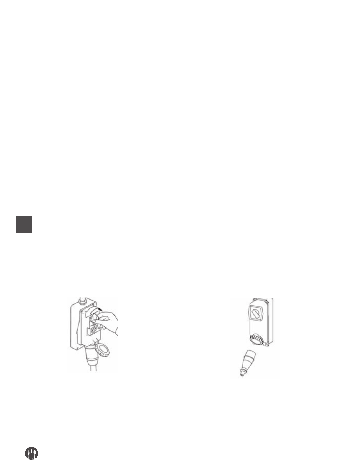
PL
52
ODBLOKOWYWANIE W PRZYPADKU ZATRZYMANIA SIĘ URZĄDZENIA
Podczas pracy lub obrotu tarcz urządzenie może się
zablokować z powodu:
• dostania się produktów spożywczych pomiędzy
niewłaściwe części,
• lub podania zbyt twardych lub zbyt suchych produktów.
Urządzenie może podobnie zareagować na przerwę
w zasilaniu lub gdy zostanie zatrzymane z produktem spożywczym w środku.
Aby przywrócić normalną pracę należy zdemontować
tarcze: demontaż należy wykonać zgodnie z wcze-
śniejszymi zaleceniami.
ROZDZ. 5. KONSERWACJA, ROZWIĄZYWANIE PROBLEMÓW ORAZ CZYSZCZENIE
WYMOGI KONSERWACJI
Pojęcie „konserwacji” dotyczy nie tylko okresowych
przeglądów urządzenia pod kątem prawidłowego
funkcjonowania, ale również analizy oraz zastosowania odpowiednich środków zaradczych wobec
wszelkich przyczyn niesprawności. Czynności kons-
erwacji, czyszczenia, wymiany części oraz rozwiązywania problemów muszą być wykonywane przez
wykwalifikowane osoby upoważnione przez praco-
dawcę.
Wszystkie czynności konserwacji, czyszczenia oraz
wymiany części należy wykonywać po wyłączeniu
urządzenia oraz odłączeniu od zewnętrznych źródeł
zasilania.
ZALECENIA DOTYCZĄCE KONSERWACJI
ZDEJMOWANIE OSŁON I/LUB URZĄDZEŃ ZABEZPIECZAJĄCYCH
W przypadku niektórych interwencji opisanych w
tym rozdziale konieczne jest zdemontowanie
stałych osłon. Demontażu może dokonywać wyłącz-
nie konserwator.
Po zakończeniu czynności naprawczych osłony należy ponownie zamontować i zablokować w oryginalnym położeniu, stosując odpowiednie mocowania
zdjęte przed naprawą.
Przed przystąpieniem do demontażu stałych osłon i/lub wymiany części konserwator musi całkowicie
wyłączyć urządzenie.
ODŁĄCZENIE OD ŹRÓDŁA ZASILANIA
Przed przystąpieniem do konserwacji, czyszczenia lub wymiany części, należy odłączyć urządzenie od źródła zasilania.
Ustawić w położeniu zerowym urządzenie zabezpieczające znajdujące się na końcu linii zasilania elektrycznego przed urządzeniem.
Odłączyć wyłącznik i odpowiednio zabezpieczyć
wtyczkę.
Page 53

PL
53
ROZWIĄZYWANIE PROBLEMÓW LUB USTEREK ORAZ ODBLOKOWYWANIE ELEMENTÓW RUCHOMYCH
Poniżej przedstawiono czynności interwencyjne związane z rozwiązywaniem problemów i usuwaniem usterek oraz odblokowywaniem elementów ruchomych, które mogą być wykonywane przez konserwatorów.
TYP POTENCJALNA PRZYCZYNA ELEMENT I PORÓWNANIE
Brak napięcia
sieciowego
Całkowity brak zasilania Skontaktować się z dystrybutorem energii
elektrycznej.
Zadziałanie bezpieczników lub
wyłączników termo-magnetycznych
w linii zasilającej przed urządzeniem
Po wyeliminowaniu przyczyn powodujących
zadziałanie zabezpieczenia, przywrócić je do
stanu poprzedniego. W przypadku powracania
problemu skontaktować się z elektrykiem.
Zadziałanie interwencyjne
Zadziałanie zabezpieczenia wewnątrz
urządzenia
Skontaktować się z elektrykiem: po wyeliminowaniu przyczyn powodujących zadziałanie
zabezpieczenia, przywrócić je do stanu
poprzedniego.
W przypadku zadziałania bezpieczników
wymienić je na bezpieczniki tego samego typu,
tego samego modelu, mocy i krzywej
zadziałania.
Podnoszenie uchwytu docisku
(migająca zielona dioda LED)
Po podniesieniu uchwytu docisku urządzenie
natychmiast się zatrzymuje na skutek
uruchomienia mikroprzełącznika.
Obniżyć docisk do wysokości, która uniemożliwia włożenie palców do strefy tnącej.
Zdemontować pokrywę górną
(migająca czerwona dioda LED)
Po zdemontowaniu pokrywy górnej urządzenie
natychmiast się zatrzymuje na skutek
uruchomienia mikroprzełącznika.
Założyć prawidłowo pokrywę górną
i zablokować odpowiednim pokrętłem,
a następnie uruchomić urządzenie.
Przyczyna niezdefiniowana Skontaktować się bezpośrednio z autoryzowa-
nym centrum serwisowym
Urządzenie nie działa:
tarcze nie obracają się
lub nie wykonują cięcia
prawidłowo
Brak napięcia zasilania (nie świecą
żadne diody LED).
Sprawdzić i przywrócić zasilanie elektryczne.
Wyłącznik w położeniu „O” nie świecą
żadne diody LED)
Ustawić wyłączniki w położeniu „ON”
Uruchomione bezpieczniki
lub niesprawne wyłączniki
termo-magnetyczne.
Wymienić wyzwolone bezpieczniki, sprawdzić
stan wyłączników termo-magnetycznych.
Niesprawny czerwony przycisk Sprawdzić działanie przycisku „I”; w razie
potrzeby skontaktować się bezpośrednio
z autoryzowanym centrum serwisowym.
Uszkodzony mikroprzełącznik, zużyte
lub uszkodzone tarcze tnące
Skontaktować się bezpośrednio z autoryzowanym centrum serwisowym
Hałas lub skrzypienie są spowodowane luźnym pasem napędowym
Skontaktować się bezpośrednio z autoryzowanym centrum serwisowy
Page 54

PL
54
KONSERWACJA NADZWYCZAJNA
W przypadku konserwacji nadzwyczajnej przeprowadzanej w następstwie usterek, przeglądów lub
uszkodzeń mechanicznych oraz elektrycznych (na
przykład naprężanie pasów transmisyjnych, itp.) konieczne jest zwrócenie się do certyfikowanego serwisu.
MYCIE
Zabrania się ręcznego czyszczenia podzespołów
i elementów ruchomych.
Czyszczenie należy rozpoczynać wyłącznie po
oczyszczeniu urządzenia z żywności i odłączeniu
elektrycznego źródła zasilania oraz zasilania zewnętrznego.
Urządzenia, sprzętu elektrycznego ani elementów
tablicy rozdzielczej nie wolno czyścić wodą, ani
strumieniowymi urządzeniami myjącymi; nie wolno więc stosować do mycia także wiader, gąbek ani
szmatek. Nie wkładać urządzenia bezpośrednio do
zlewu ani pod bieżącą wodę.
Klasyfikacja poziomu higieny urządzenia oraz powiązanego osprzętu dla zastosowań zgodnych z przeznaczeniem to poziom 2 (drugi): urządzenie, które po ocenie ryzyka higienicznego nie spełnia wymogów
odpowiednich norm międzynarodowych, ale wymaga programowego demontażu do czyszczenia.
CZĘSTOTLIWOŚĆ PERSONEL SPOSÓB POSTĘPOWANIA
Na końcu każdej zmiany,
a w każdym przypadku
przed użyciem w danym
dniu
Operator Wszystkie powierzchnie oraz części urządzenia przeznaczone do
kontaktu z żywnością lub znajdujące się w strefie produktów
spożywczych (powierzchnia wewnętrzna otworów podajnika i wyładowczego, docisku, kołka dociskowego, strefy tnącej, tarcz obrotowych
i nieruchomych, pokrywy górnej, osłon stałych) oraz strefy obu-
dowy (zewnętrzna powierzchnia urządzenia) należy czyścić i dezynfekować w opisany poniżej sposób. Instrukcja demontażu grupy
tnącej znajduje się w poprzednich opisach.
• Zeskrobać z powierzchni ewentualne resztki produktów spo-
żywczych (na przykład plastikowym skrobakiem);
• Należy oczyścić wszystkie powierzchnie strefy kontaktu z żywnoś-
ci
ą oraz strefy zewnętrznej miękką szmatką zwilżoną (nieka-
piącą) detergentem rozpuszczonym w ciepłej wodzie (można
także użyć zwykłego płynu do mycia naczyń). Nie namaczać. Należy używać produktów przeznaczonych do stali, płynnych (nie
emulsji ani past, które mają właściwości ścierne), które przede
wszystkim nie mogą zawierać chloru. Do usuwania tłuszczu
można używać denaturatu.
• Spłukać czystą ciepłą wodą, a następnie osuszyć całą po-
wierzchnię strefy kontaktu z żywnością oraz strefy zewnętrznej miękkimi szmatkami, niepozostawiającymi włókien.
• Części ze stali nierdzewnej można również myć w zmywarce.
• Ponowny montaż należy wykonywać z zachowaniem wymogów
dotyczących obsługi maszyny; części pozostawić zawinięte w miękkie
suche szmatki niepozostawiające włókien.
Page 55
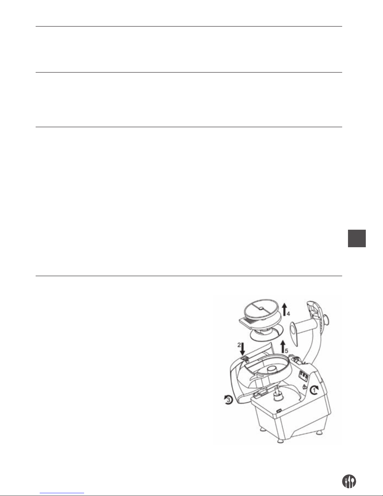
PL
55
DŁUGIE OKRESY PRZESTOJU
• Podczas długich okresów wyłączenia wszystkie powierzchnie
stalowe (zwłaszcza ze stali nierdzewnej) należy przetrzeć energicznie szmatką nasączoną olejem wazelinowym, aby nałożyć
powłokę ochronną.
CZEGO NIE NALEŻY ROBIĆ PRZED CZYSZCZENIEM LUB PO NIM:
• Zbliżać się do części ruchomych bez wcześniejszego sprawdzenia, czy zostały zatrzymane;
• Zbliżać się do części ruchomych bez ich zatrzymania w sposób
gwarantujący bezpieczeństwo (blokada urządzeń odcinających
zasilanie elektryczne w pozycji zerowej)
PRODUKTY, KTÓRYCH NIE NALEŻY STOSOWAĆ:
• Dysze ze sprężonym powietrzem w strefach nagromadzenia
mąki oraz ogólnie skierowane w stronę urządzenia;
• Urządzenia parowe;
• Detergenty zawierające CHLOR (również rozcieńczone) lub jego
związki, np.: wybielacz, kwas chlorowodorowy, produkty do
czyszczenia odpływów, produkty do czyszczenia marmuru, ogólnie produkty odwapniające, itp. mogą atakować stal powodując
jej trawienie i utlenianie. Opary wymienionych powyżej produktów mogą utleniać się i powodować korozję stali;
• Wełna stalowa, stalowe szczotki lub tarcze ścierne produkowane
z innych metalów lub stopów (np. zwykła stal, aluminium, mosiądz, itp.) lub narzędzia, którymi wcześniej czyszczono inne metale lub stopy, ponieważ mogą zarysować powierzchnię.
• Detergenty w proszku ściernym;
• Benzyna, rozpuszczalniki lub płyny łatwopalne i/lub żrące;
• Substancje stosowane do czyszczenia srebra.
DEMONTAŻ/MONTAŻ W CELU CZYSZCZENIA
1. Obrócić pokrętło blokady (1) pokrywy górnej (2),
nacisnąć przycisk (2) i oburącz obrócić pokrywę górną (3)
2. Zdjąć z trzpienia obrotowego tarcze tnące (obrotowe
i stałe) oraz tarczę wyrzucającą (4), zdemontować
pojemnik z tworzywa sztucznego (5).
Page 56
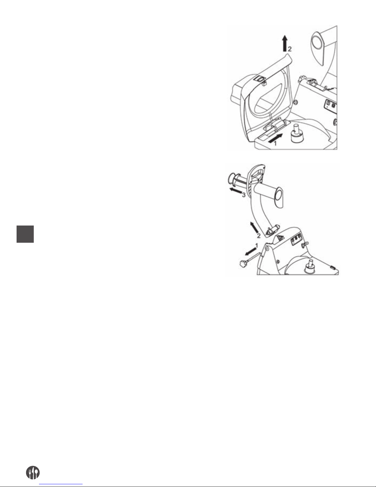
PL
56
3. Zdjąć pokrywę górną (2) z trzpienia,
na którym się obraca (1)
4. Podnieść uchwyt docisku do oporu w górę.
5. Zdemontować czop zabezpieczający (1)
6. Wyczepić z gniazda uchwyt docisku (2),
podnosząc g w górę
7. Obrócić kołek dociskowy, aby go zdemontować (3).
ROZDZ. 6. UTYLIZACJA
Jeżeli urządzenie nie będzie już więcej używane ze
względu na to, że jest przestarzałe lub nieodwracalnie uszkodzone albo zużyte do tego stopnia, że naprawa jest nieopłacalna, należy je w bezpieczny sposób wycofać z eksploatacji. Wycofanie z eksploatacji
należy powierzyć wyspecjalizowanemu personelo-
wi dysponującemu odpowiednim wyposażeniem.
Po zakończeniu czynności związanych z wycofaniem z eksploatacji należy usunąć wszystkie etykie-
ty identyfikacyjne oraz zniszczyć całą dokumentację
urządzenia.
Urządzenie można zutylizować bez konieczności
rozbierania go na drobne części; wystarczy rozmontować główne podzespoły i umieścić je w pojemnikach,
w których będą transportowane do punktu
utylizacji.
Utylizację należy przeprowadzić zgodnie z obowiązującymi normami, we współpracy z odpowiednimi
organami lub firmą specjalizującą się w złomowaniu
urządzeń przemysłowych lub utylizacji odpadów, ze
względu na wymóg oddzielenia tworzyw sztucznych,
metalu oraz podzespołów elektrycznych, które muszą
być oddane do poszczególnych punktów zbiórki.
Obowiązkiem pracodawcy jest znajomość krajowych przepisów oraz ich przestrzeganie.
Page 57

PL
57
Pozostawienie maszyn oraz urządzeń elektrycznych w środowisku jest zabronione i podlega karze.
Symbol skreślonego kosza na śmieci umieszczony
na urządzeniu oznacza produkt, który po wycofaniu
z eksploatacji należy utylizować oddzielnie od innych
odpadów.
Użytkownik ma obowiązek oddać urządzenie do odpowiedniego punktu zbiórki zajmującego się utylizacją zużytych urządzeń elektronicznych i elektrycznych.
ROZDZ. 7. MATERIAŁY, Z KTÓRYCH WYKONANO URZĄDZENIE
Zgodnie z wymaganiami działania i produkcyjnymi, urządzenie może zawierać różne materiały.
GRUPA RODZAJ MATERIAŁU
Stal nierdzewna Stal nierdzewna Tworzywo sztuczne Aluminium
18/8 AISI 304 do kontaktu do kontaktu
z żywnością z żywnością
Korpus szatkownicy •
Górna zdejmowalna pokrywa •
Otwóry podajników •
Otwór wyładowczy •
Tarcze obrotowe • • •
Elementy tnące tarcz obrotowych •
Tarcze nieruchome • • •
Elementy tnące tarcz nieruchomych •
Tarcza wyrzucająca •
Kołek dociskowy •
Komora tnąca •
Page 58

FR
58
INDICE
CAP. 1. ORGANISATION DU CONTENU ET MODALITES DE CONSULTATION ..... 59
CAP. 2. INFORMATIONS GENERALES ET CARACTERISTIQUES..........................60
CAP. 3. INSTRUCTIONS POUR LA SECURITE ...................................................... 64
CAP. 4. TRANSPORT, MISE EN SERVICE ET EMPLOI .......................................... 66
CAP. 5. ENTRETIEN, RECHERCHE PANNES ET NETTOYAGE ............................. 71
CAP. 6. ELIMINATION ........................................................................................... 76
CAP. 7. MATERIAUX DE CONSTRUCTION ............................................................ 77
Page 59

FR
59
CHAP. 1. ORGANISATION DU CONTENU ET MODALITES DE CONSULTATION
BUT DU MANUEL
IMPORTANCE DU MANUEL
Le mode d’emploi présent doit être considéré comme partie intégrante de la machine:
• il doit être gardé pendant toute la vie de la machine.
• il doit accompagner la machine en cas de cession
de la même.
• outre à rapporter toutes les informations utiles
pour les opérateurs, il contient (recueillis en des
chapitres spécifiques), les schémas électriques
qui serviront pour les interventions éventuelles
d’entretien et réparation.
BUT / FINALITES DU MANUEL
La notice d’utilisation a le but de fournir au client
toutes les informations nécessaires afin que, outre à
un emploi adéquat de la machine fournie, il soit en
état de gérer la même dans la façon la plus autonome et sure possible.
En outre, le manuel présent a été rédigé dans le but
de fournir des indications et des avertissements
pour connaître la machine fournie, pour comprendre
ses principes et limites de fonctionnement. Pour des
doutes éventuels appeler le Centre d’Assistance Autorisé.
DESTINATAIRES
Le mode d’emploi présent, livré en numéro de nr. 1
copie avec la machine, et fourni comme partie intégrante du même, s’adresse soit aux opérateurs soit
aux techniciens qualifiés habilités à l’installation,
emploi et entretien.
Le responsable du service de prévention et protection du client et les préposés ultérieurs auxquels la
machine est destinée, doivent prendre vision du
mode d’emploi présent dans le but d’ adopter toutes
les mesures techniques et organisationnelles.
RESPONSABILITES
• Au cas où le manuel présent subirait des endommagements ou serait égaré, il est possible en demander une copie au Centre d’ Assistance Autorisé.
• Le manuel présent reflète l’état de la technique
au moment de la construction de la machine; le
constructeur se réserve le droit de mettre à jour
la production et par conséquent d’autres éditions
du manuel, sans l’obligation de mettre à jour les
productions ou les manuels précédant, sinon en
des cas particuliers concernant la santé et la sécurité des personnes.
• Faire particulièrement attention au contenu des
risques résidus présents sur la machine et les
prescriptions que les opérateurs doivent suivre.
• Le constructeur se considère responsable pour
la machine dans sa configuration originelle.
• Le constructeur ne se considère pas responsable
pour des endommagements provoqués par l’em-
ploi impropre ou non correct de la machine et de
la documentation ou pour des endommagements
provoqués par l’effraction de normes impératives, négligence, maladresse, imprudence et non
respect de normes réglementaires de la part de
l’employeur, de l’opérateur ou du manutentionnaire et pour toute panne éventuelle causée par
un emploi irraisonnable, impropre et/ou incorrect
• Le constructeur ne se considère pas responsable
pour les conséquences provoquées par l’emploi
de pièces de rechanges non originelles ou de caractéristiques équivalentes.
• Le constructeur se considère responsable seule-
ment pour les informations rapportées dans la
version originelle du manuel en langue italienne.
• L’inobservance des prescriptions contenues dans
ce manuel provoquera l’immédiate déchéance de
la garantie.
Page 60
FR
60
Les responsables d’usine, qui dirigent les activités
de travail, doivent, dans le domaine des attributions
et compétences respectives:
• Réaliser les mesures de sécurité prévues;
• Informer les opérateurs des risques spécifiques
auxquels ils sont exposés et faire leur connaître
les normes essentielles de prévention;
• Disposer et exiger que chaque opérateur observe
les normes de sécurité et emploie les moyens de
protection mis à leur disposition:
– Placer plus d’un opérateur, en contemporaine,
au travail sur ce produit manufacturé.
SIGNIFICATION DE LA SYMBOLOGIE
Ci de suite on spécifique clairement la signification des symboles et des définitions qui seront utilisés dans
le document présent.
DANGER
Il indique la présence d’un danger pour celui qui opère sur la machine et pour celui qui se
trouve dans les environs donc l’activité signalée doit être effectuée en respectant les normes
anti-accidents en vigueur et les indications rapportées dans le manuel présent.
PRECAUTION
Il indique un avertissement sur des informations utiles et/ou des recommandations ultérieures et/ou des procédés concernant l’opération en cours.
ATTENTION
Il indique une opération à exécuter avec attention pour éviter d’endommager la machine.
CAP. 2. INFORMATIONS GENERALES ET CARACTERISTIQUES
DESTINATION EMPLOI ET PARTIES CONSTRUCTIVES
Le coupe-légumes ci de suite appelée “machine”, est projeté pour trancher, couper en petits cubes et râper
des fruits, des légumes frais de tous les types connus (courgettes, carottes, céleris, pommes de terre,
poivrons, tomates, etc…) et d’autres de consistance analogue à ceux-ci.
La machine est composée d’ un moteur électrique
introduit dans une fusion unique (corps machine
base), où l’arbre moteur est branché à l’outil de coupe à l’aide de courroies de transmission faites
exprès.
Le produit alimentaire chargé manuellement peut
être positionné:
1. dans le clapet d’alimentation pour former des
petits cubes ou effiler ou latter, placé dans la
zone supérieure gauche de la machine et toujours
manuellement, en actionnant le presseur à l’aide
de son manche, le produit est poussé contre la
zone de coupe. Le chargement du produit doit être
effectué en quantité modérée pour éviter qu’ en
baissant le presseur la machine démarre, à cause
du manche du micro-interrupteur de sécurité
placé dans le bloc du presseur;
2. dans le clapet d’ alimentation pour couper, placé
dans la zone supérieure droite de la machine et
toujours manuellement et à l’aide du pilon il est
introduit dans le goulot de la machine vers la zone
de coupe. Le pilon est en matériel plastique
propre au contact avec des produits alimentaires.
Le clapet d’alimentation pour former des petits
cubes et le clapet d’alimentation pour couper
sont positionnés sur le couvercle de fermeture
bloqué à la machine à l’aide d’un pommeau fait
exprès: sur la machine il est placé un microinterrupteur de sécurité qui relève la position correcte
du couvercle.
Page 61
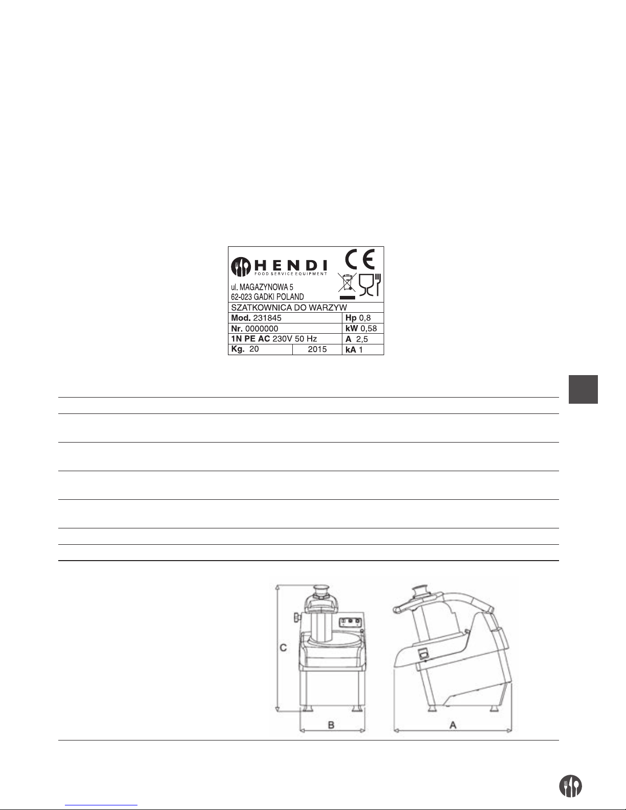
FR
61
La zone de coupe de la machine comprend sa zone
intérieure où l’on peut positionner manuellement
des disques roulants munis de fixation à baionnette
avec l’arbre moteur et d’autres disques fixes:
• disques roulants pour trancher et râper;
• disques roulants pour trancher;
• disques roulants pour trancher en forme d’allumettes;
• disques fixes pour former des petits cubes;
• disques fixes pour coupe à baguettes;
• disque éjecteur roulant.
Dans la zone inférieure antérieure de la machine est
présente le clapet de déchargement, à travers lequelle le produit alimentaire coupé déborde.
Tous les matériaux à contact direct avec le produit
alimentaire sont conformes aux normatives en vigueur hygiéniques pour les aliments.
Selon les exigences de fonctionnement et de production, la machine peut être composée de différentes pièces optionnelles.
La machine est douée de plaquette d’ identification
sur laquelle elles sont rapportées les données
suivantes:
DONNEES TECHNIQUES ET CONSTRUCTIVES
Puissance moteur (kW) / (Hp) 0,58kW / 0,80Hp
Dimension interne clapet d’alimentation
pour former des petits cubes (mm)
180 x 80
Longueur goulot du clapet d’ alimentation
pour former des petits cubes (mm)
150
Dimension interne clapet d’alimentation pour
couper (mm)
57
Hauteur goulot du clapet d’alimentation pour
couper (mm)
190
Production horaire (kg/h) 250-450
Masse (kg) 21,5
Dimensions encombrement: A x B x C (mm) 490 x 280 x 530
Page 62
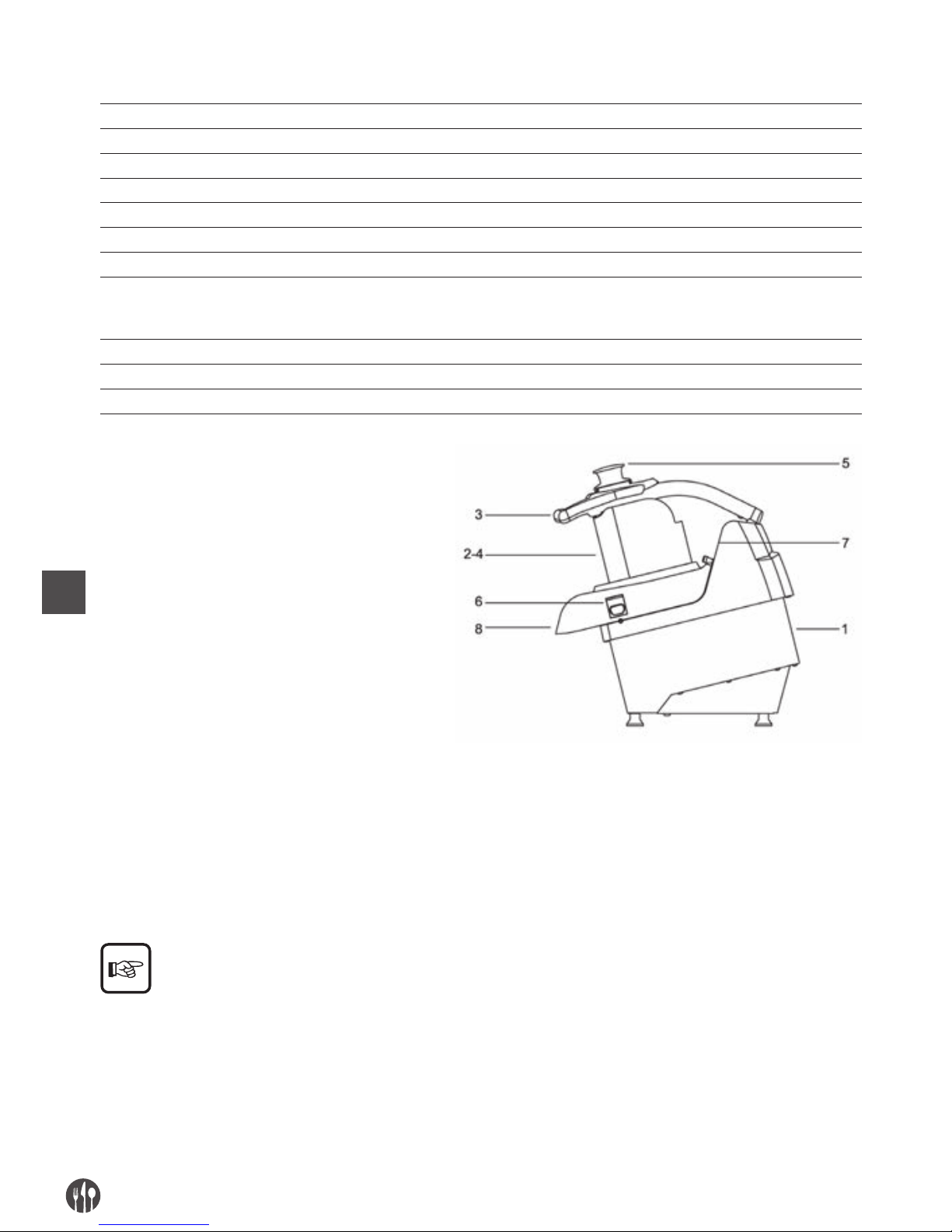
FR
62
Niveau de puissance acoustique continu
équivalent pondéré A
Mineur de 70dBA
Nature du courant - Fréquence Cfr. Plaque de la machine
Courant à pleine charge Cfr. Plaque de la machine
Tension nominale d’emploi Cfr. Plaque de la machine
Tension des circuits auxiliaires AC 24V – DC 24V
Masse et neutre TT et TN
Degré de protection IP X3
Lieu d’emploi A l’intérieur
Positionnement de la machine Banc de travail employé dans le secteur alimentaire de hauteur
comprise entre 900/1100mm de la surface de piétinement de portée
adéquate, avec un espace libre de circulation d’au moins 800mm
Température air milieu max +40°C
Eclairage minimum demandé 500 lux
Conformité directives de produit 2006/42/CE, 2006/95/CE, Reg. 1935/2004
1. corps machine
2. clapet d’alimentation pour tranches
3. manche presseur
4. clapet d’alimentation pour petits cubes
ou baguettes
5. pilon
6. pommeau de blocage du couvercle
7. panneau de commande
8. clapet de déchargement
EMPLOI NORMAL, EMPLOI IMPROPRE, EMPLOI NON CORRECT OU INTERDIT
La machine décrite dans le mode d’emploi présent
est prévue pour être conduite par un seul opérateur
formé et instruit sur les risques résidus, mais avec
les compétences, en matière de sécurité, des préposés à l’entretien. L’opérateur devra posséder au
moins l’âge minimum prévu par les lois sociales
dans le milieu du travail et avoir joui de la préparation technique nécessaire au moins d’ un opérateur
plus expert qui l’ait préalablement formé dans
l’emploi correct de la machine.
Dans son EMPLOI NORMAL, et raisonnablement
prévisible, la machine peut être employée seulement pour couper en petits cubes et râper fruits,
légumes frais de tous les types connus, cour-
gettes,carottes, céleris, pommes de terre, poivrons, tomates, etc… et d’autres de consistance
analogue à ceux-ci.
Page 63

FR
63
La machine ne doit pas être utilisée DE FAÇON IMPROPRE; en particulier:
• elle ne doit pas être employée pour des emplois
doméstiques,
• il ne faut pas la faire marcher avec des paramètres
différents de ceux rapportés dans la tabelle des
caractéristiques techniques,
• pour tout emploi de la machine avec modalités
différentes de celles indiquées dans le manuel
présant, le constructeur en décline toute responsabilité,
• celui qui l’utilise est responsable des dommages
résultants de la non observance des conditions
d’exercice concordées en siège de spécification
technique et de confirmation de commande,
• les disques doivent être ceux des configurations
indiquées,
• introduire des produits alimentaires secs et non
humides ou dégouttant,
• ne pas forcer ou détériorer volontairement ni enlever ou cacher les étiquettes.
La machine ne doit pas être utilisée DE FAÇON INCORRECTE c’est -à-dire INTERDITE puisque l’on pourrait
provoquer des dommages ou blessures pour l’opérateur; en particulier:
• il est interdit de déplacer la machine quand elle
est branchée à l’alimentation électrique;
• il est interdit de tendre le câble d’ alimentation
électrique ou la machine pour débrancher la
fiche d’alimentation,
• il est interdit de positionner des poids sur la machine ou sur le câble d’ alimentation électrique,
• il est interdit de positionner le câble d’ alimenta-
tion électrique sur des parties coupantes ou avec
danger de brûlure,
• il est interdit l’emploi de la machine avec le câble
d’ alimentation électrique ou les dispositifs de
commande endommagés et non intacts;
• il est interdit de laisser la machine arrêtée avec
le câble d’ alimentation électrique branché à la
fiche d’ alimentation,
• il est interdit de laisser la machine chargée non
gardée;
• il est interdit d’introduire n’importe quel objet à
l’intérieur de la calotte de ventilation du moteur;
• il est interdit de positionner la machine sur des
objets différents d’ un banc de travail employé
dans le secteur alimentaire de hauteur compris
entre 900 - 1100mm de la surface de piétinement,
• il est interdit d’introduire n’importe quel type
d’objet sous le bâti de la machine ou positionner
des chiffons ou autre chose entre les pieds-debiches d’appui de la machine et le banc de travail,
• il est interdit l’emploi de substances inflammables,
corrosives ou nuisibles pour le nettoyage,
• il est interdit de plonger la machine dans l’eau ou
d’autres liquides;
• il est interdit l’emploi à un personnel non autori-
sé et avec des vêtements différents de ceux indiqués pour l’emploi,
• il est interdit d’ introduire dans la zone de coupe
et dans la bouche de déchargement, les mains ou
n’importe quelle autre partie du corps, pour enlever le produit alimentaire coupé;
• il est interdit d’introduire dans le clapet de dé-
chargement, n’importe quel objet, tel que par
exemple des lames de couteaux, etc…,
• il est interdit d’ enlever le couvercle bloqué à la
machine pendant l’ usinage de la machine ou de
toute façon quand on a déposé du produit alimentaire à usiner,
• il est interdit pendant le fonctionnement d’es-
sayer d’ouvrir ou soulever le couvercle, renverser la machine, ouvrir ou enlever le carter de
protection placé sur le fond,
• il est interdit de relâcher le pommeau de bloc
couvercle bloqué à la machine soit pendant l’usi-
nage et de toute façon avant 5 sec de la com-
mande d’arrêt de la machine,
• il est interdit le fonctionnement avec les abris de
protection fixes et mobiles non bloqués correctement ou enlevés;
• il est interdit l’enlèvement partiel des protections
et des signalisations de danger.
• il est interdit le fonctionnement si l’utilisateur n’a
pas adopté tous les mesures concernant l’élimi-
nation des risques résidus,
• il est interdit de fumer ou utiliser des appareil-
lages à flamme libre et manipuler des matériaux
• incandescents, à moins que l’on adopte des mesures de sécurité aptes,
• il est interdit d’actionner ou régler les dispositifs
de contrôle et de blocage tels que pommeaux ou
• semblables soit pendant le fonctionnement de la
machine, soit si l’on n’est pas autorisés
Page 64
FR
64
L’utilisateur est de toute façon responsable des
dommages résultant de la non observance des
conditions d’emploi normal spécifiées. Pour des
doutes éventuelles s’adresser au Centre d’ Assistance Autorisé.
CAP. 3. INSTRUCTIONS POUR LA SECURITE
PREFACE
La non application des normes et procédures de
sécurité peut être source de danger et de dommage.
La machine s’entend engagée dans l’emploi au res-
pect, de la part de l’utilisateur final, de:
• toutes les règles, d’introduction dans le milieu et
de conduite des personnes, établies par les lois
et/ou normes appliquables; avec une référence
particulière à l’installation fixe en amont de la
machine fournie et pour son branchement /fonctionnement;
• tous les instructions et avertissements d’emploi
ultérieurs faisant partie des documents technique/graphiques jointe à la machine même.
Sauf où différemment spécifié, le personnel qui
exécute les interventions d’ installation, branchement, entretien, réinstallation et réutilisation, recherche pannes ou avaries, démolition et démantè-
lement doit être un personnel expert formé en
matière de sécurité et instruit sur les risques résidus, avec les compétences, en matière de sécurité,
des préposés à l’entretien.
MILIEUX, PLACES DE TRAVAIL ET DE PASSAGE
Le milieu de travail doit répondre aux conditions de
la directive 89/654/CEE. Dans l’aire de travail ils ne
doivent pas être présents des objets étrangers.
L’ employeur, selon la directive 89/391/CEE, concernant la réalisation de mesures destinées à favoriser
l’améliorement de la sécurité et de la santé des travailleurs pendant le travail, doit pourvoir à éliminer
ou réduire les risques résidus indiqués comme prévu dans le manuel présent.
AVERTISSEMENTS CONCERNANT LES RISQUES RESIDUS
RISQUE RESIDU DU A L’ENLEVEMENT DES ABRIS FIXES, MOBILES, INTERVENTIONS SUR DES PARTIES
CASSEES/USEES
Pour n’importe quelle éventualité l’opérateur ne
doit jamais essayer d’ouvrir ou enlever un abri fixe
ou mobile ou forcer un dispositif de sécurité.
Dans la phase de préparation des outillages, d’ entretien, de remplacement des outils et de nettoyage, et pendant toutes les opérations manuelles
ultérieures qui sont effectuées en introduisant les
mains ou d’autres parties du corps dans les aires
dangereuses de la machine, il demeure un risque
résidu dû surtout à:
• collisions avec parties constructives de la machine,
• frottement et/ou abrasion avec parties rugueuses
de la machine,
• piqûre avec les parties pointues,
• découpage avec parties affilées des outils.
Page 65
FR
65
En outre dans la phase de chargement, avec le
presseur soulevé qui est effectué aussi en introdui-
sant les mains dans les aires dangereuses de la machine, il demeure un risque résidu dû surtout à dé-
coupage avec des parties affilées des outils.
En outre dans la phase de nettoyage ou déblocage
des pièces encastrées dans les disques qui est ef-
fectué aussi en introduisant les mains à proximité
des lames de découpage, il demeure un risque résidu dû surtout à découpage avec des parties affilées
des outils.
L’opérateur et le manutentionnaire doivent être for-
més pour l’intervention liée aux opérations manuelles avec des abris ouverts, ils doivent être ins-
truits sur les risques conséquent liés, ils doivent
être autorisés par une personne responsable et
doivent employer des dispositifs de protection individuelle adéquats, des gants antidécoupage à cinq
doigts. Toutes les interventions sur les disques
doivent être effectuées en les tenant avec les lames
adressées vers le bas.
DISPOSITIFS DE PROTECTION SUR LA MACHINE
Les protections et les dispositifs de sécurité de la
machine ne doivent pas être enlevés.
Au cas où ils devraient être enlevés pour des exigences d’ entretien extraordinaire l’on devra immé-
diatement adopter des mesures propres à mettre
en évidence et à reduire à la limite minimum possible le danger qui en dérive.
La remise en place de la protection ou du dispositif
de sécurité doit être effectuée dès que les raisons
qui ont rendu nécessaire leur enlèvement temporain
sont cessées.
Tous les dispositifs de protection et de sécurité de la
machine, soit électriques soit mécaniques, doivent
être maintenus en des conditions de parfaite et
constante efficacité.
Les organes de transmission de la machine sont
complètement isolés à l’aide de protections fixes qui
ne permettent l’accès à aucune chaîne cinématique.
Pour toutes les fonctions de sécurité comprenant
les systèmes de commande et contrôle, ont été utilisés des composants et des principes de sécurité
bien essayés.
GROUPE PORTEOUTILS:
1. Considérées les modalités d’emploi de la machine
et de sa destination d’emploi, les éléments mobiles sont isolé par des abris fixes, abris mobiles
ou d’autres dispositifs de sécurité, placés à des
distances des points d’accès tels qu’il n’est pas
possible atteindre des points dangereux;
2. sur le groupe du manche et du presseur, il est placé un micro-interrupteur qui arrête la rotation
des outils quand il est possible accéder à travers
le clapet d’alimentation;
3. le clapet d’alimentation pour couper présente une
longueur adéquate: les outils résultent être pla-
cés à des distances des points d’ accès tels que
l’on ne peut pas les atteindre;
4. sur le couvercle de la zone supérieure de la machine, il est placé un micro-interrupteur qui arrête la rotation des outils quand il est possible
accéder à travers la zone de déchargement;
5. dans la zone de déchargement à correspondance
de l’écoulement du produit, la conformation particulière du disque éjecteur et des disques roulants ne permet pas à la main ou partie d’elle d’atteindre les organes en mouvement et de toute
façon avec des points dangereux;
Page 66
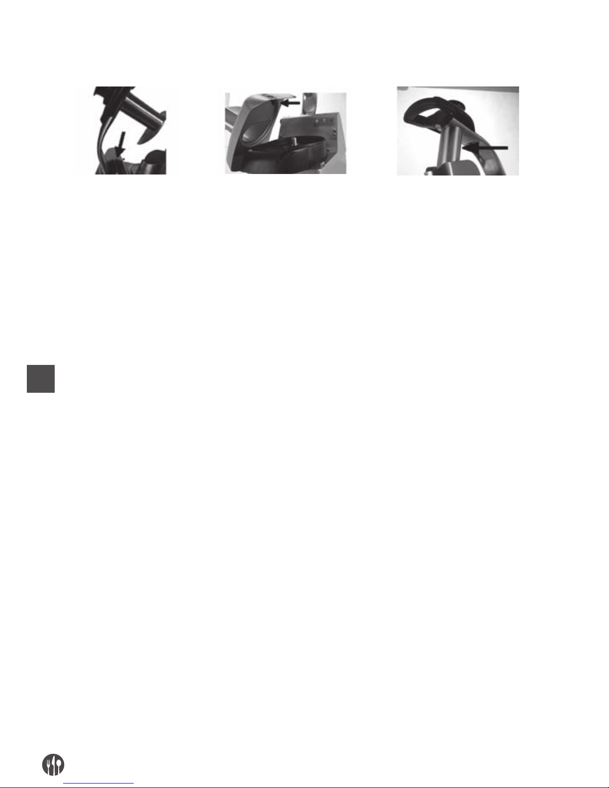
FR
66
Manche du presseur
avec microinterrupteur
Couvercle supérieur démontable
avec micro-interrupteur
Abri fixe clapet d’alimentation
pour couper
CAP. 4. TRANSPORT, MISE EN SERVICE ET EMPLOI
POSTES DE TRAVAIL ET FONCTIONS DES OPERATEURS
Comme indiqué dans le mode d’emploi, la machine
est projetée pour être conduite par un opérateur
formé et instruit sur les risques résidus, mais avec
les compétences, en matière de sécurité, des préposés à l’entretien.
La zone normale de travail de l’opérateur est:
1. la zone latérale de la machine à proximité des
bouches de chargement (définie zone de chargement) en des conditions normales de fonctionnement pour les opérations de chargement manuel
du produit alimentaire et pendant l’emploi du pilon pour convoyer le produit alimentaire dans le
col de la machine, avec les abris fixes et mobiles
en position fermés et bloqués;
2. la zone antérieure de la machine à proximité de la
zone de déchargement du produit alimentaire en
des conditions normales de fonctionnement pour
les opérations de prélèvement manuel du produit
alimentaire déposé dans un conteneur fait exprès,
avec les abris fixes et mobiles en position fermés
et bloqués
OPERATIONS PRELIMINAIRES DE PREPARATION
STABILITE
La stabilité de la machine est projetée de façon que,
dans les conditions de fonctionnement prévues,
compte tenu des conditions climatiques, elle soit
consentie l’utilisation sans le risque de renverse-
ment, de chute ou de déplacement intempestif.
Compte tenu de la conformation et de sa position, la
machine résulte être intrinsèquement stable sans
nécessité de fixation au banc de travail. Tous les
pieds-de-biche d’appui placés sous le bâti doivent
appuyer sur une surface solide, uniforme et bien nivelée.
ALIMENTATION ELECTRIQUE
Le branchement de l’alimentation électrique doit être en conformité avec la législation pertinante du pays
dans lequel elle est employée.
L’alimentation électrique doit donc être maintenue en conformité aves les prescriptions techniques suivantes:
1. l’alimentation électrique doit être toujours du
type et avoir une intensité correspondante aux
spécifications indiquées dans la plaque de la machine. Si l’on applique des tensions excessives,
l’on endommagera irréparablement des composants,
2. il faut prévoir un dispositif différentiel coordon-
né avec le circuit de protection, en respectant la
législation et les dispositions législatives et réglementaires en vigueur dans le pays d’installation;
3. le câble pour l’alimentation électrique hors de
l’enveloppe de la machine doit être fait passer
dans les espaces que vous avez préparés et
convenablement protegés;
4. si le conducteur de neutre (N) est présent avant
Page 67
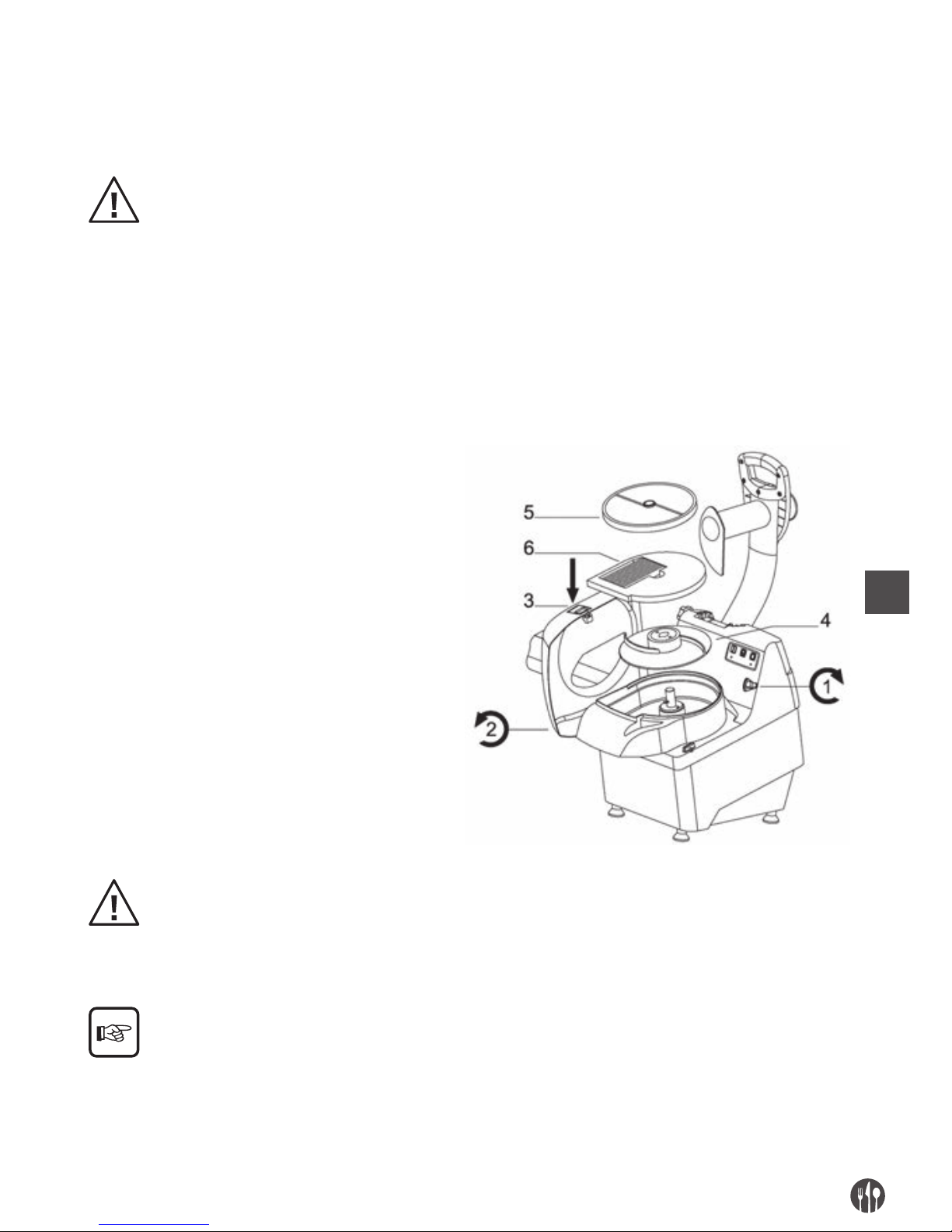
FR
67
d’alimenter l’équipement électrique, vous devez
garantir sa continuité (branché et disponible).
5. avant d’alimenter l’équipement électrique, vous
devez garantir sa continuité (branché e disponible) du conducteur jaune vert du circuit équipotentiel de protection.
ASSEMBLAGE / DESASSEMBLAGE
Les opérations d’ assemblage / désassemblage de
n’importe quel organe de la machine doivent être
effectuées quand la machine est arrêtée et avec la
fiche débranchée de la prise, c’est-à-dire avec le
dispositif de sectionnement en OFF.
L’assemblage des outils sur la machine se déroule en des différentes phases.
1. Tourner le bouton poussoir de serrage (1) du rabat
supérieur (2), appuyer sur la touche et tourner le
rabat supérieur (2) avec les deux mains
2. Sur le moyeu rotatif, insérer en premier le disque
expulsif (4) en faisant attention à que les broches
d’entraînement présentes sur le moyeu s’insèrent
dans les trous existant sur le disque;
3. Pour les travaux qui nécessitent l’utilisation d’un
seul disque, insérer sur le moyeu le disque
rotatif (5) au-dessus du disque expulseur (4).
(Voir les tableaux du chapitre n° 2)
4. Pour les travaux qui nécessitent l’utilisation
de deux disques à la fois, insérer sur le bouton
poussoir rotatif les éléments suivant dans
cet ordre : (voir les tableaux du chapitre n° 2).
1° - Disque éjecteur (4)
2° - Disque fixe (6)
3° - Disque roulant (5)
5. Remettre le rabat supérieure (2)
en le tournant
6. Fermer le bouton poussoir de serrage (1)
en le tournant dans le sens antihoraire.
Après avoir inséré les disques selon les exigences d’usinage, vérifier l’accrochage à baionette correct des
mêmes dans le moyeu roulant.
Le disque éjecteur DOIT ETRE TOUJOURS OBLIGATOIREMENT monté, afin que les disques puissent
opérer en position correcte. Pour l’emploi optimal
de tous les types de disques roulants et l’emploi
contemporain éventuel des disques roulants avec
ceux fixes, consulter les tabelles du chapitre nr. 2,
portant toutes les possibles combinaisons fonctionnelles.
Page 68
FR
68
Les activités de désassemblage sont effectuées en suivant à rebours les phases d’assemblage précédemment
décrites.
ROTATION DES DISQUES DE DECOUPAGE
Les opérations imdiquées ci-de suite doivent être effectuées par le manutentionnaire de la machine (per-
sonnel spécialisé dans le secteur de l’entretien électrique des machines industrielles).
Pour des machines alimentées avec tension triphasée (3 PE AC 400V 50Hz), presser le poussoir de
commande à action maintenue ”
”, et vérifier le cor-
rect sens de rotation des disques de découpage à tra-
vers le clapet d’alimentation pour couper, en le comparant avec le sens indiqué par la flèche (sens
anti-horaire) placée sur le couvercle de la machine.
Au cas où il y aurait une rotation dans le sens
contraire à celui de la flèche (sens horaire), arrêter la
machine en débranchant la fiche, la désassembler, débrancher deux conducteurs de phase et les invertir de
position.
DESCRIPTION DU FONCTIONNEMENT
Les dispositifs de commande sont projetés et
construits de façon telle à être très sûres et fiables
et résistants aux sollicitations normales de service,
aux efforts prévisibles et aux agents extérieurs. En
outre, ils sont clairement visibles, repérables et
marqués par un marquage approprié. Ci de suite ils
sont rapportés les principaux dispositifs de com-
mande:
TYPE / COULEUR REFERENCE / DESCRIPTION
Poussoir / noir ”O” / Poussoir pour la commande d’arrêt de la machine
Poussoir / blanc “ I ” / Poussoir pour la commande de démarrage de la machine avec impulse
Poussoir / blanc “ ” / Poussoir pour la commande de démarrage de la machine à action maintenue
SIGNALATIONS COUPE
TYPE / COULEUR REFERENCE / DESCRIPTION
Led fixe rouge Machine branchée avec le rabat supérieur fermé et le pressoir baissé
Led clignotante rouge Machine branchée avec le rabat supérieur ouvert
Led fixe verte Machine bronchée en service
Led clignotante verte Machine branchée avec le bouton de démarrage de la machine appuyé
et avec le pressoir soulevé.
Avec l’abaissement du pressoir la machine démarre (led fixe verte)
DEMARRAGE
Le démarrage avec impulse de la machine est possible seulement avec une action volontaire sur le
dispositif de commande prévu dans ce but: poussoir
blanc “I” pour la commande de démarrage de la machine.
ARRET
Pour la commande d’arrêt actionner le poussoir noir
“O”. En cas d’ arrêt momentané ou prolongé, avant
de remettre en marche la machine, il faut enlever
toutes les produits alimentaires dans la machine:
suivre les indications concernant le désassemblage
du groupe de broyage.
Page 69

FR
69
DEMARRAGE A ACTION MAINTENUE
Le démarrage à action maintenue de la machine est
possible seulement avec une action volontaire sur
le dispositif de commande prévu dans ce but: pous-
soir blanc
” ”
pour la commande de démarrage
de la machine. En relâchant le poussoir la machine
s’arrête.
ABSENCE DE TENSION
En cas d’interruption de l’alimentation électrique ou
si la machine est débranchée du réseau électrique,
celle-ci pourra être redémarrée seulement suivant
la fonction de démarrage, après le retour de l’ali-
mentation électrique ou le rebranchement au réseau électrique.
OUVERTURE DU PRESSEUR
En soulevant par le manche le presseur, la machine
s’arrête immédiatement pour l’entrée en fonction du
micro-interrupteur de sécurité. La machine peut
être redémarrée seulement en baissant le presseur
jusqu’à l’hauteur qui ne permet pas l’introduction
des doigts vers la zone de découpage et suivant ensuite la fonction de démarrage.
ENLEVEMENT DU COUVERCLE DE LA MACHINE
En relâchant le pommeau de blocage et en enlevant
le couvercle avec les deux mains, la machine s’arrête immédiatement pour l’entrée en fonction du
micro-interrupteur de sécurité. La machine peut
être redémarrée seulement en repositionnant le
couvercle de la machine et bloquant avec le pommeau fait exprès et suivant ensuite la fonction de
démarrage.
CONTROLES ET VERIFICATIONS AVANT LA MISE EN MARCHE
VERIFICATION / CONTROLE MODALITES ET CONTROLES
S’assurer que:
• Il n’y ait pas sur la machine,
dans les clapets d’alimentation et à correspondance du
clapet de déchargement zone
de déversement du produit
des objets étrangers
Contrôle visuel des parties indiquées, pour s’assurer de l’absence d’objets ou
corps étrangers tels que par ex. des outils différents, des draps, etc… et que, de
toute façon, il n’y ait pas le produit alimentaire.
En cas de présence pourvoir à leur enlèvement.
S’assurer du nettoyage:
• Des parties intérieures de la
machine
• De la zone de découpage, des
disques, de la partie
intérieure du couvercle de la
machine, de la bouche de
déchargement
• Du presseur et du pilon
• De la surface extérieure de la
machine
Toutes les surfaces des parties indiquées, avant l’emploi de la machine doivent
être contrôlées visuellement pour s’assurer de leur nettoyage.
Pour le contrôle visuel des parties intérieures de la zone de découpage, enlever
le couvercle supérieur.
En cas de présence de moisissures ou d’autre type de saleté, pourvoir à la
procédure de nettoyage selon les indications dont il est question au chapitre 5.
Page 70

FR
70
S’assurer de l’intégrité:
• des abris fixes
• du couvercle supérieur de
fermeture
• des clapets d’alimentation
et de décharge
• du presseur
• du corps de la machine
Tous les abris fixes, etc.. doivent effectuer la fonction pour laquelle ils ont été
prévus.
Contrôle visuel des parties indiquées pour s’assurer de leur intégrité dans
la partie extérieure de leur surface.
Les parties doivent être de toute façon remplacées aux premiers signes
d’érosion ou rupture (cfr. Centre d’ Assistance Autorisé).
S’assurer de la fonctionnalité:
• des parties du système
de commande / contrôle
concernant la sécurité;
• des dispositifs de commande.
Tous les dispositifs doivent avoir la fonction pour laquelle ils ont été prévus.
Commander dirèctement les dispositifs afin qu’ils déterminent la fonction
attendue.
Les actionneurs et toutes les parties doivent être de toute façon remplacés aux
premiers signes d’ érosion ou rupture (cfr. Centre d’ Assistence Autorisé).
S’assurer de l’absence:
• de bruits étranges après
la mise en marche
Pendant la vérification de la fonctionnalité des dispositifs de commande, au cas
où il y aurait des bruits étranges, dûs par exemple à un grippage ou ruptures
mécaniques, arrêter immédiatement la machine, et activer le service
d’entretien.
Pour n’importe quel type d’intervention ou pour le
remplacement des parties qui résultent endommagées, activer le service d’ entretien. Le remplacement éventuel doit être effectué avec des produits
originaux du constructeur ou au moins de qualité,
sécurité et caractéristiques équivalentes. Pour tout
approfondissement contacter le Centre d’ Assistence Autorisé.
MISE EN FONCTION
L’opérateur de la machine peut mettre en marche la machine, en suivant dans l’ordre les indications rapportées ci-dessous:
• Issue positive des contrôles dont il est question
dans opérations préliminaires de préparation,
• Issue positive des contrôles dont il est question
dans l’alimentation électrique,
• Branchement de la fiche dans une prise de courant opportune,
• Issue positive des contrôles dont il est question
dans assemblage (contrôle positionnement
disques, etc…),
• Issue positive des contrôles dont il est question
dans la correcte rotation des disques,
• Issue positive des contrôles / vérifications avant
la mise en marche,
• Issue positive des contrôles finalisés à vérifier le
respect de toutes les conditions de sécurité,
• Positionner le couvercle dans la zone supérieure
de la machine et serrer le pommeau de blocage;
• Positionner une poche de vidange dans la zone
antérieure de la machine à correspondence du
clapet de déchargement du produit alimentaire;
• Se positionner dans la zone gauche de la machine
et la démarrer en actionnant le dispositif de commande de START “I”,
• Introduire manuellement le produit alimentaire
dans les clapets de chargement selon les exigences d’usinage et le pousser vers le bas / zone
de découpage ou en baissant graduellement le
manche du presseur ou en le poussant avec le pilon en dotation, en exerçant une légère pression
pour obtenir le meilleur résultat opérationnel,
sans soumettre à un effort anomal les organes de
transmission. Quand le presseur ou le pilon arrivent à fin course, les relever et répéter les opérations décrite ci-dessus en continuant jusqu’à
l’achèvement du cycle de travail,
• A la fin de l’introduction du produit alimentaire,
c’est-à-dire quand de la zone de déchargement ne
déborde plus le produit, arrêter la machine en actionnant le dispositif de commande de STOP “O”.
Page 71

FR
71
COUPURE
En succession, les opérations de coupure doivent suivre ce qui est indiqué ci de suite:
• avant la coupure attendre la conclusion de la sortie du produit alimentaire du clapet de déchargement en poussant complètement vers le bas le
manche du presseur et le pilon,
• arrêter la machine en actionnant le dispositif de
commande de STOP “O”,
• débrancher la fiche de la machine de la prise
d’ alimentation,
• exécuter les interventions de nettoyage.
DEBLOCAGE EN CAS D’ OBSTACLES
Pendant l’usinage, c’est-à-dire pendant la rotation
de l’outil, à cause:
1. de l’introduction de produits alimentaires avec
des parties non homogènes,
2. de l’introduction de produits excessivement durs
et secs, la machine pourrait se bloquer.
La même situation peut se vérifier suite à une panne
de l’alimentation électrique, c’est-à-dire quand la
machine est arrêtée avec le produit alimentaire à
son intérieur.
Pour pouvoir reprendre normalement l’usinage les
disques doivent être enlevés: le désassemblage
doit suivre les prescriptions indiquées en précédence.
CAP. 5. ENTRETIEN, RECHERCHE PANNES ET NETTOYAGE
QUALITES REQUISES DU MANUTENTIONNAIRE
Par le terme “entretien” il ne faut pas seulement entendre le contrôle périodique du normal fonctionnement de la machine mais aussi l’analyse et le remède conséquent de toutes ces causes qui pour une
raison ou pour l’autre la mettent hors de service. Il
est absolument nécessaire que pour les activités d’
entretien, nettoyage, remplacement parties et recherche pannes effectuées par l’utilisateur, cette
tâche soit confiée à un personnel expert, compétent
et autorisé par l’employeur.
Toutes les opérations d’ entretien, nettoyage et
remplacement pièces, aucune exclue, doivent être
forcement exécutées avec la machine complètement arrêtée et isolée des sources d’ alimentation
extérieures.
PRESCRIPTIONS D’ENTRETIEN
ENLEVEMENT DES ABRIS ET/OU DISPOSITIFS DE PROTECTION
Pour quelques interventions dont il est question
dans le chapitre présent, il est nécessaire enlever
de leur position quelques abris fixes.
L’ enlèvement peut être effectué seulement de la par
du manutentionnaire.
A la fin des interventions, ces abris, doivent être placés et bloqués dans leur position originelle, avec les
systèmes de fixation qui étaient prévus avant l’intervention.
Le responsable de l’entretien doit désactiver complètement la machine, comme ci-de suite rapporté,
avant de procéder à l’enlèvement d’ un abri fixe et/ou au remplacement d’ un élément.
Page 72
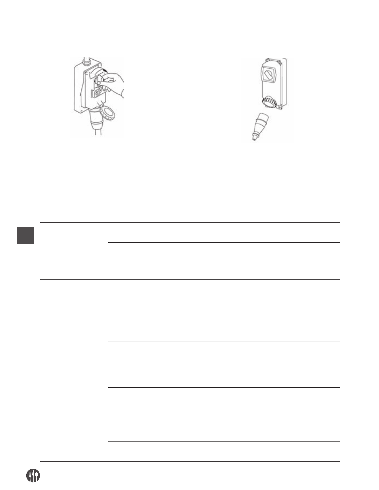
FR
72
ISOLEMENT DES SOURCES D’ ALIMENTATION EXTERIEURS
Avant d’exécuter n’importe quelle opération entretien, nettoyage et remplacement pièces, il faut sectionner
et isoler les sources d’ alimentation extérieures.
Positionner sur “zéro” le dispositif de protection placé en amont de la ligne d’alimentation de l’équipement électrique.
Débrancher le dispositif de sectionnement général
et pourvoir à protéger la fiche avec des systèmes fait
exprès.
RECHERCHE PANNES OU AVARIES ET DEBLOCAGE ELEMENTS MOBILES
Ci de suite elles sont indiquées les interventions pour la recherche pannes ou avaries et déblocage éléments mobiles qui peuvent être effectuées par des manutentionnaires.
TYPE POTENTIEL/S CAUSE/S MODALITES ET CONTROLES
Absence tension
de réseau
Black out général Contacter l’organisme distributeur de l’énergie
électrique
Intervention de fusibles ou
magnétothermiques placés en amont
de la ligne d’alimentation de la
machine
Après avoir éliminé les causes qui ont
déterminé l’intervention du dispositif de
protection, le rétablir. En cas de persistence du
problème contactez un technicien électricien.
Interruption de
fonctionnement
Intervention du dispositif de
protection intérieur à la machine
Contactez un technicien électricien: après avoir
éliminé les causes qui ont déterminé
l’intervention d’ un dispositif de protection, le
rétablir.
En cas d’intervention de fusibles, les remplacer
avec des types du même modèle, tarage et
courbe d’intervention.
Soulèvement de la manchette du
pressoir (led clignotante vert)
Si la poignée du pressoir est sulevée,
la machine s’arrête immédiatement à cause de
l’entrée en service du micro bouton de sécurité.
Baisser le pressoir jusqu’à une hauteur qui
évite de mettre les doigts dans la zone de coupe.
Enlèvement du couvert supérieur
(led clignotante rouge)
Si on enlève le couvercle supérieur, la machine
s’arrête immédiatement à cause de la mise en
service du micro bouton de sécurité.
Positionner correctement le couvercle
supérieur et le bloquer avec le bouton
poussoir. Démarrer la machine.
Cause/s non identifiables Contacter directement le Centre d’ Assistance
Autorisé
Page 73
FR
73
La machine ne marche
pas: les disques
ne tournent pas ou
n’exécutent pas
le découpage
correctement
Manque de courant
(toutes les leds éteintes)
Contrôler et rétablir l’énergie électrique.
Dispositifs de sectionnement sur
« O » (toutes les leds éteintes)
Tourner les dispositifs de sectionnement dans
la position “ON”
Fusibles intervenus ou magnétothermiques non fonctionnant.
Faire remplacer les fusibles intervenus,
contrôler l’état des interrupteurs
magnéto-thermiques.
Non fonctionnement du poussoir de
marche
Contrôler l’efficacité du poussoir de “I”
et éventuellement contacter directement
le Centre d’ Assistance Autorisé.
Micro-interrupteur en panne Contacter directement le Centre d’Assistance
Autorisé
Disques de découpage usés ou ruinés Contacter directement le Centre d’Assistance
Autorisé
Courroie de transmission lente
détermine aussi émission de bruit
ou grincement
Contacter directement le Centre d’Assistance
Autorisé
ENTRETIEN EXTRAORDINAIRE
Pour les interventions d’ entretien extraordinaire,
conséquentes à des ruptures ou révisions ou pannes
mécaniques ou électriques (par ex. la tension des
courroies de transmission du mouvement, etc…),
elle est nécessaire une demande d’intervention di-
rèctement au Centre d’ Assistance Autorisé.
Les instructions concernant l’entretien extraordinaire ne paraissent pas dans le mode d’emploi présent et doivent donc être exprèssement demandées
au fabricant.
NETTOYAGE
Il est interdit de nettoyer à main les organes et les
éléments en mouvement.
Toutes les interventions de nettoyage doivent être
effectuées seulement et exclusivement après avoir
déchargé la machine avec le produit alimentaire en
usinage et l’avoir isolée de la source d’alimentation
électrique et d’énergie extérieures.
La machine, l’appareillage électrique et les composants à bord machine ne doivent jamais être lavés
en utilisant de l’eau, surtout en forme de jets de
n’importe quelle nature et quantité; donc, sans
“séau” ni “caoutchouc” ni “éponge”. Ne poser ja-
mais dirèctement la machine dans le lavabo ou sous
le robinet.
La classification du niveau d’hygiène de la machine
et des outillages associés, pour l’emploi prévu, est
2 (deux): machine qui, suite à une évaluation du
risque d’hygiène, est conforme aux qualités re-
quises des normes internationales appliquables,
mais demande un désassemblage programmé pour
le nettoyage.
Page 74

FR
74
FREQUENCE PERSONNEL MODALITES
A la fin de chaque équipe de
travail et de toute façon
avant l’emploi journalier
Opérateur Toutes les surfaces et les parties de la machine destinées à entrer
en contact avec le produit alimentaire, c’est-à-dire, les zones ali-
mentaires (surface intérieure des clapets d’alimentation et déchargement, le presseur, le pilon, la zone de découpage, les disques
roulants et fixes, le couvercle supérieur, les abris fixes) et les zones
éclaboussures (surface extérieure de la machine), doivent être nettoyées et désinfectées avec les modalités rapportées ci-dessous.
Pour les activités de désassemblage du groupe de découpage, voir
les descriptions précédantes.
• Ecrouter les surfaces des résidus de produit alimentaire éven-
tuels (par ex. avec des gratteurs en plastique);
• Nettoyer toutes les surfaces de la zone alimentaire et zone
éclaboussures avec un chiffon mou mouillé (non égouttant) avec
du détérgent dilué dans de l’eau chaude (aussi du commun sa-
von pour la vaisselle ira très bien). Ne les pas laisser tremper.
Utiliser des produits spécifiques pour acier, ils doivent être liquides (non en crème ou pâtes de toute façon abrasives) et surtout ils ne doivent pas contenir de chlore. Contre les substances
graisses l’on peut utiliser l’alcool dénaturé.
• Rincer avec de l’eau chaude nettoyée et ensuite sécher toutes
les surfaces de la zone alimentaire et zone éclaboussures avec
un chiffon mou qui ne perde pas de poils.
• Les parties en acier inox, peuvent être lavées aussi dans la
lave-vaisselle.
• Le remontage doit être effectué seulement suite à une exigence
d’usinage, laisser les pièces enveloppées dans un chiffon mou
sec qui ne perde pas de poils
PERIODES DE LONGUE INACTIVITE
• Pendant les périodes de longue inactivité de la machine pourvoir à passer énergiquement sur toutes les surfaces en acier
(spécialement si inox) un chiffon imbibé d’huile de vaseline de
façon telle à étendre un voile protectif.
CHOSES A NE PAS FAIRE AVANT OU PENDANT LE NETTOYAGE:
• Accéder aux éléments mobiles sans s’être préventivement assurés de leur arrêt;
• Accéder aux éléments mobiles sans l’avoir arrêtée en sécurité
garantie (blocage dans la position de zéro des dispositifs de sectionnement de l’alimentation életrique)
Page 75
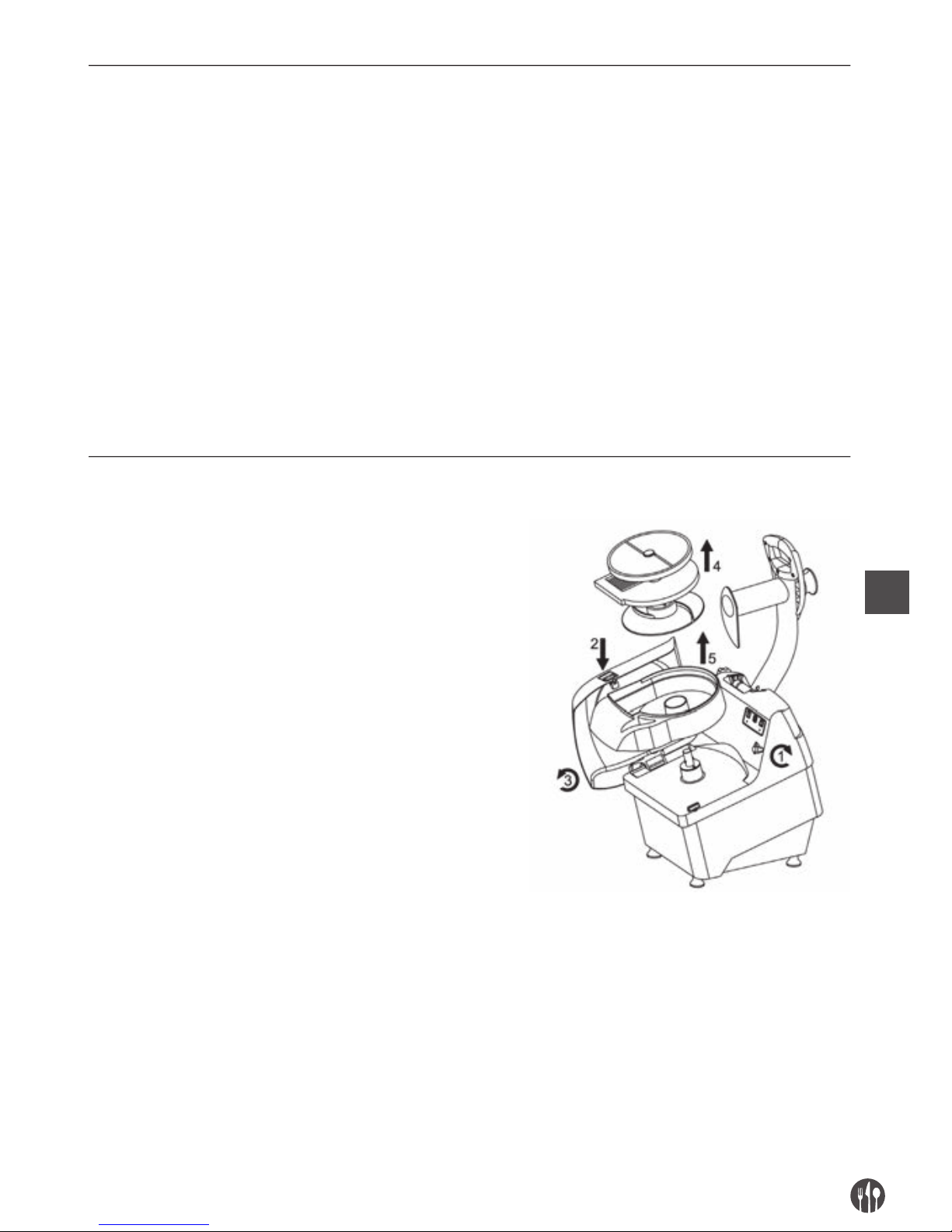
FR
75
PRODUITS A NE PAS UTILISER:
• Air comprimé avec des jets vers les zones avec des dépôts de
farine et en général vers la machine;
• Appareillages à vapeur;
• Détérgents qui contiennent du CHLORE (même si dilués) ou ses
composés tels que: l’eau de Javel, l’acide muriatique, des produits pour déboucher la vidange, produits pour le nettoyage du
marbre, décalcifiants en général, etc … peuvent attaquer la composition de l’acier, en le tachant ou en l’oxydant irréparablement.
Les seules émanations des susmentionnés produits peuvent
oxyder et en certains cas ronger l’acier;
• Paille de fer, brosses ou disquettes abrasifs réalisés avec
d’autres métaux ou alliages (ex. acier commun, aluminium, laiton, etc…) ou des outils qui aient en précédence nettoyé d’autres
métaux ou alliages, qui griffent les surfaces.
• détérgents en poudre abrasifs;
• essence, solvants ou fluides inflammables et/ou corrosifs;
• substances employées pour nettoyer l’argent.
DEMONTAGE / MONTAGE POUR LE NETTOYAGE
1. Tourner le moyeu de serrage (1) du rabat
supérieur, appuyer sur la bouton (2) et avec
les deux mains tourner le rabat supérieur (3)
2. Sortir du pivot rotatif, les disques de coupe
(rotatif et fixe) et le disque expulsif (4).
Enlever le pot en plastique (5).
Page 76
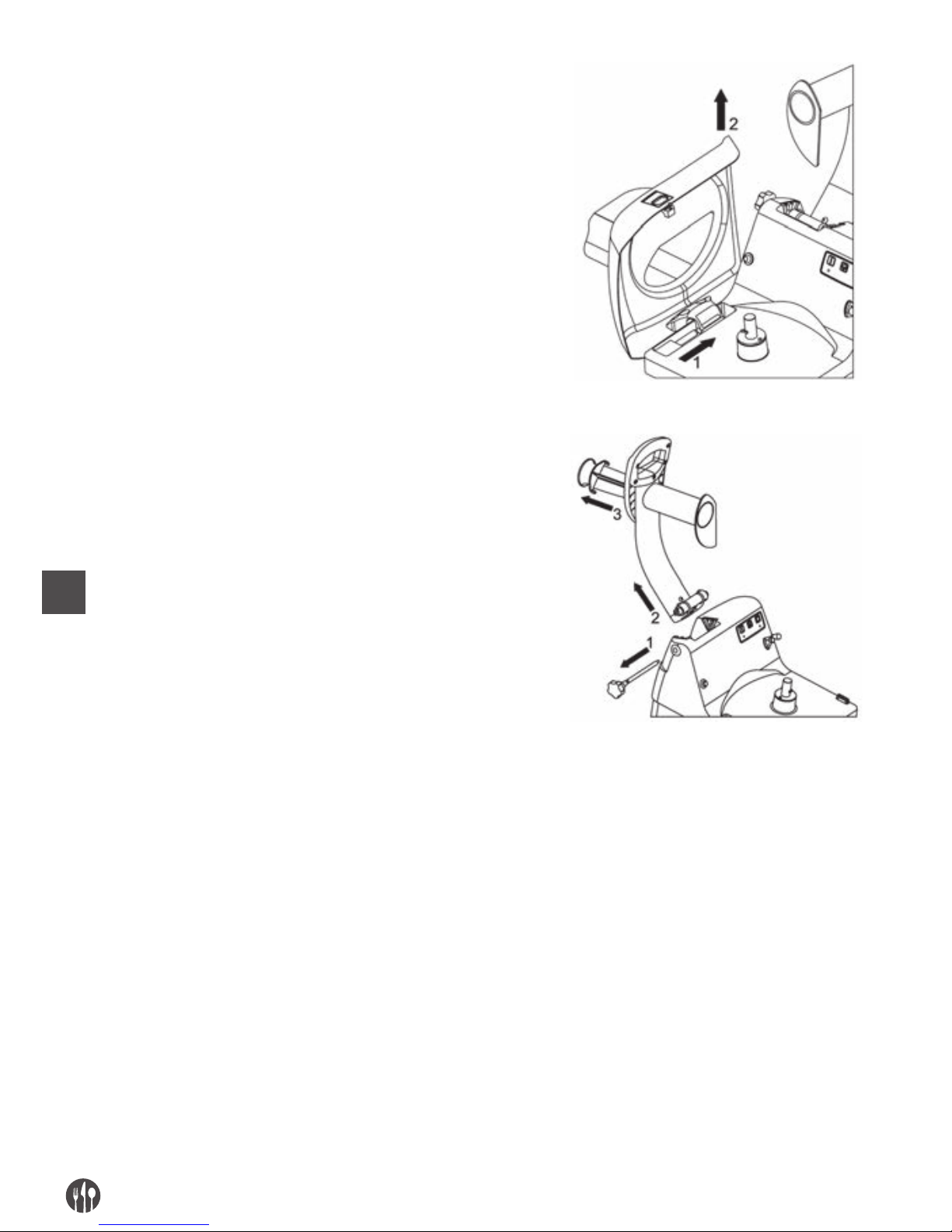
FR
76
3. Enlever (2) le rabat supérieur en le
retirant du pivot sur lequel il tourne (1)
4. Positionner la poignée du pressoir en fin
de course.
5. Retirer le pivot de sécurité (1)
6. Décrocher la poignée du pressoir du site (2)
en le tirant vers le haut
7. Tourner et puis sortir le pilon (3).
CAP. 6. ELIMINATION
Dans le cas où vous décidez de ne plus utiliser la
machine à cause de son ancienneté, d’un endommagement ou de l’usure (état irréparable), procédez à
son démantèlement. Rendez la machine inoffensive
et inopérante. Son démantèlement doit être effectué
par un personnel spécialisé et équipé.
Une fois les activités de démantèlement terminées,
toutes les plaques d’identification et les documents
de la machine doivent être détruits.
L’élimination de la machine ne nécessite pas son
broyage. Il suffit de déconnecter les groupes princi-
paux qui composent la machine et les envoyer à la
mise au rebut.
S’occuper du démantèlement en respectant les normes en vigueur; en s’adressant aux organismes
prévus et/ou aux entreprises spécialisées dans le
démantèlement industriel et/ou des déchets afin de
séparer le matériau en plastique de celui en métal et
de composants électriques qui doivent être envoyés
au site de recyclage.
L’employeur est tenu de connaître les lois en vigueur dans son pays afin de bien respecter ces normes.
Page 77
FR
77
Il est interdit d’abandonner la machine et son équipement électrique dans la nature sous peine de sanctions.
Le symbole de la benne à ordures barrée présent
sur la machine signifie que le produit doit être séparé des autres déchets à la fin de sa durée de vie.
L’utilisateur est tenu d’apporter la machine inutilisable dans les centres prévus pour le recyclage des
déchets électroniques et électrotechniques.
CAP. 7. MATERIAUX DE CONSTRUCTION
Selon les exigences de fonctionnement et de production, la machine peut être constituée avec des différentes typologies de matériaux de construction.
GROUPE TIPOLOGIA MATERIALI
Acier inox Acier inox Plastique pour Alluminium traité
18/8 AISI 304 aliments pour aliments
Corps machine •
Couvercle amovible supérieur •
Clapets de chargement •
Clapet de déchargement •
Disques roulants • • •
Elements de découpage des disques
roulants
•
Disques fixes • • •
Eléments de découpage des disques
fixes
•
Disque éjecteur •
Pilon •
Presseur •
Rabat supérieur •
Pot de coupe •
Page 78

IT
78
INDICE
CAP. 1.
ORGANIZZAZIONE DEL CONTENUTO E MODALITÀ DI CONSULTAZIONE
.. 79
CAP. 2. INFORMAZIONI GENERALI E CARATTERISTICHE .................................. 80
CAP. 3. ISTRUZIONI PER LA SICUREZZA............................................................. 84
CAP. 4. TRASPORTO, MESSA IN SERVIZIO ED USO ............................................ 86
CAP. 5. MANUTENZIONE, RICERCA GUASTI E PULIZIA ...................................... 91
CAP. 6. SMALTIMENTO ......................................................................................... 95
CAP. 7. MATERIALI DI COSTRUZIONE ................................................................. 96
Page 79

IT
79
CAP. 1. ORGANIZZAZIONE DEL CONTENUTO E MODALITÀ DI CONSULTAZIONE
SCOPO DEL MANUALE
IMPORTANZA DEL MANUALE
Il presente manuale delle istruzioni per l’uso è da considerarsi come parte integrante della macchina:
• deve essere custodito per tutta la vita della macchina.
• deve accompagnare la macchina in caso di cessione della stessa.
• oltre a riportare tutte le notizie utili per gli operatori, contiene (raccolti in capitoli specifici), gli
schemi elettrici che serviranno per gli eventuali
interventi di manutenzione e riparazione.
SCOPO / FINALITÀ DEL MANUALE
Il Manuale delle istruzioni per l’uso ha lo scopo di
fornire al committente tutte le informazioni necessarie affinché, oltre ad un adeguato utilizzo della
macchina fornita, sia in grado di gestire la stessa nel
modo più autonomo e sicuro possibile.
Inoltre il presente manuale è stato redatto allo scopo di fornire indicazioni ed avvertenze per conoscere la macchina fornita, per comprendere i suoi principi e limiti di funzionamento. Per eventuali dubbi
interpellare il Centro di Assistenza Autorizzato.
DESTINATARI
Il presente manuale delle istruzioni per l’uso, consegnato in numero di n. 1 copia assieme alla macchina, viene fornito come parte integrante dello stesso,
è rivolto sia agli operatori che ai tecnici qualificati
abilitati all’installazione, uso e manutenzione.
Il responsabile del servizio di prevenzione e protezione del committente e gli ulteriori addetti cui è
destinata la macchina, devono prendere visione del
presente manuale delle istruzioni per l’uso, al fine di
adottare tutte le misure tecniche ed organizzative
RESPONSABILITÀ
• Nel caso il presente manuale subisca danneggiamenti o venga smarrito, è possibile richiederne
copia al Centro di Assistenza Autorizzato.
• Il presente manuale rispecchia lo stato della tec-
nica al momento della costruzione della macchina; il costruttore si riserva il diritto di aggiornare
la produzione e di conseguenza altre edizioni del
manuale, senza l’obbligo di aggiornare produzioni
o manuali precedenti, se non in casi particolari
riguardanti la salute e la sicurezza delle persone.
• Porre particolare attenzione al contenuto dei ri-
schi residui presenti sulla macchina e le prescrizioni a cui devono attenersi gli operatori.
• Il costruttore si ritiene responsabile per la macchina nella sua originale configurazione.
• Il costruttore non si ritiene responsabile per
danni arrecati dall’uso improprio o non corretto
della macchina e della documentazione o per danni arrecati dalla violazione di norme imperative,
negligenza, imperizia, imprudenza e non rispetto
di norme regolamentari da parte del datore di lavoro, dell’operatore o del manutentore e per ogni
eventuale guasto causato da un uso irragionevole, improprio e/o sbagliato
• Il costruttore non si ritiene responsabile per le
conseguenze causate dall’uso di parti di ricambio
non originali o di caratteristiche equivalenti.
• Il costruttore si ritiene responsabile solo per le
informazioni riportate nella versione originale del
• manuale in lingua italiana.
• L’inosservanza delle prescrizioni contenute in
questo manuale provocherà l’immediato decadimento della garanzia.
I responsabili di stabilimento, che sovrintendono
alle attività lavorative, devono, nell’ambito delle rispettive attribuzioni e competenze:
• attuare le misure di sicurezza previste;
• rendere edotti gli operatori dei rischi specifici cui
sono esposti e portare a loro conoscenza le nor-
me essenziali di prevenzione;
• disporre ed esigere che i singoli operatori osservino le norme di sicurezza ed usino i mezzi di protezione messi a loro disposizione:
• porre più di un operatore, contemporaneamente,
al lavoro su tale manufatto.
Page 80
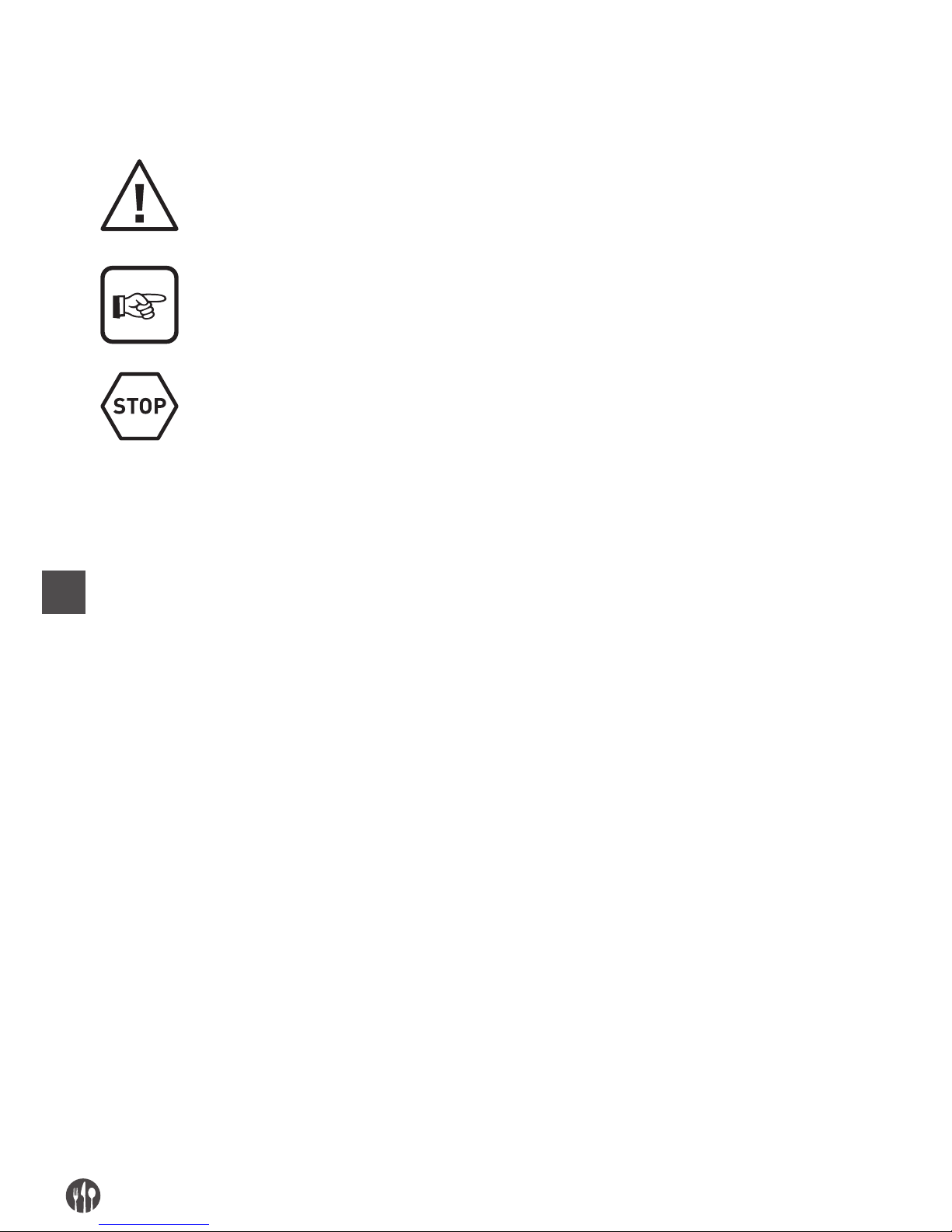
IT
80
SIGNIFICATO DELLA SIMBOLOGIA
Di seguito viene chiaramente specificato il significato dei simboli e delle definizioni che verranno utilizzate
nel presente documento.
PERICOLO
Indica la presenza di un pericolo per chi opera sulla macchina e per chi si trova nelle vicinanze perciò l’attività segnalata deve essere svolta nel rispetto delle norme antinfortunistiche
vigenti e delle indicazioni riportate nel presente manuale.
PRECAUZIONE
Indica un’avvertenza su informazioni utili e/o ulteriori raccomandazioni e/o accorgimenti inerenti l’operazione in corso.
ATTENZIONE
Indica un’operazione da eseguire con attenzione per evitare di arrecare danno alla macchina.
CAP. 2. INFORMAZIONI GENERALI E CARATTERISTICHE
DESTINAZIONE USO E PARTI COSTRUTTIVE
Il tagliaverdure nel seguito denominata “macchina”, è progettata per affettare, tagliare a cubetti e grattugiare frutta, verdure fresche di tutti i tipi conosciuti (zucchine, carote, sedani,patate, peperoni, pomodori,
etc…) e altre di consistenza analoga a queste.
La macchina è costituita da un motore elettrico inserito in una unica fusione (corpo macchina base), in
cui l’albero motore è connesso all’utensile di taglio
tramite apposite cinghie di trasmissione.
Il prodotto alimentare caricato manualmente, può
essere posto:
1. entro la bocca di carico per cubettare o sfilaccia-
re o listellare, e azionando il pressore tramite il
suo manico, il prodotto viene spinto contro la zona
di taglio. Il carico del prodotto deve avvenire in
quantità moderata per evitare che abbassando il
pressore la macchina non si avvii, a causa del micro interruttore di sicurezza posto nel blocco del
pressore;
2. entro la bocca di carico per tagliare, e con l’ausilio del pestello viene introdotto nel collo della
macchina verso la zona di taglio. Il pestello è di
materiale plastico adatto per il contatto con prodotti alimentari.
La bocca di carico per cubettare e la bocca di carico
per tagliare sono posizionate sul coperchio di chiu-
sura bloccato alla macchina tramite un apposito pomello: sulla macchina è posto un micro interruttore
di sicurezza che rileva la giusta posizione del coperchio.
La zona di taglio della macchina comprende la sua
zona interna in cui possono essere posizionati manualmente dei dischi rotanti muniti di attacco a baio-
netta con l’albero motore ed altri dischi fissi:
• dischi rotanti per affettare e grattugiare;
• dischi rotanti per affettare;
• dischi rotanti per affettare a forma di fiammiferi;
• dischi fissi per cubettare;
• dischi fissi per taglio a listelli;
• disco espulsore rotante.
Nella zona inferiore anteriore della macchina è presente la bocca di scarico, attraverso la quale fuoriesce il prodotto alimentate tagliato.
Tutti i materiali a diretto contatto con il prodotto alimentare sono conformi alle vigenti normative igieniche per alimenti.
A seconda delle esigenze di funzionamento e di pro-
duzione, la macchina può essere costituita con diverse parti opzionali.
La macchina è provvista di targhetta di identificazione sulla quale sono riportati i seguenti dati:
Page 81
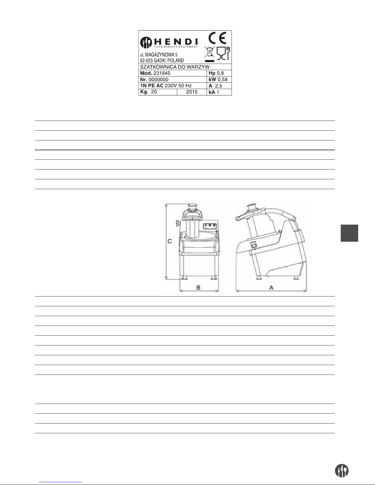
IT
81
DATI TECNICI E COSTRUTTIVI
Potenza motore (kW) / (Hp) 0,58kW / 0,80Hp
Dimensione interna bocca di carico per cubettare (mm) 180 x 80
Lunghezza collo della bocca di carico per cubettare (mm) 150
Dimensione interna bocca di carico per tagliare (mm) 57
Altezza collo della bocca di carico per tagliare (mm) 190
Produzione oraria (kg/h) 250-450
Massa (kg) 21,5
Dimensioni ingombro: A x B x C (mm) 490 x 280 x 530
Livello di potenza acustica continuo equivalente ponderato A Minore di 70dBA
Natura della corrente - Frequenza Cfr. targa della macchina
Corrente a pieno carico Cfr. targa della macchina
Tensione nominale d’impiego Cfr. targa della macchina
Tensione dei circuiti ausiliari AC 24V – DC 24V
Massa e neutro TT e TN
Grado di protezione IP X3
Luogo d’impiego All’interno
Posizionamento della macchina Banco di lavoro impiegato nel settore alimentare di altezza compresa
tra 900/1100mm dal piano di calpestio di adeguata portata, con uno spazio
libero di circolazione di almeno 800mm
Temperatura aria ambiente max +40°C
Illuminazione minima richiesta 500 lux
Conformità direttive di prodotto 2006/42/CE, 2006/95/CE, Reg. 1935/2004
Page 82
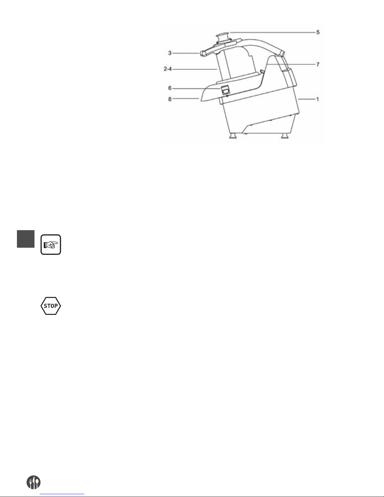
IT
82
1. corpo macchina
2. bocca di carico per fette
3. manico pressore
4. bocca di carico per cubetti o listelli
5. pestello
6. pulsante di blocco del coperchio
7. pannello di comando
8. bocca di scarico
USO NORMALE, USO IMPROPRIO, USO NON CORRETTO O VIETATO
La macchina descritta nel presente manuale delle
istruzioni per l’uso è prevista per essere condotto da
un solo operatore addestrato ed edotto sui rischi
residui, ma con le competenze, in materia di sicurezza, degli addetti alla manutenzione.
L’operatore dovrà possedere almeno l’età minima
prevista dalle leggi sociali nell’ambito del lavoro
ed aver fruito del la necessaria preparazione tecnica almeno da un operatore più esperto che lo abbia
preliminarmente addestrato all’uso corretto della
macchina.
Nel suo USO NORMALE, e ragionevolmente prevedibile, la macchina può essere utilizzata soltanto per tagliare, cubettare, sfilacciare e grattugiare frutta, verdure fresche di tutti i tipi conosciuti, zucchine,carote,
sedani,patate, peperoni, pomodori, etc… e altre di consistenza analoga a queste.
La macchina non deve essere utilizzata IN MODO IMPROPRIO; in particolare:
• non deve essere impiegata per usi domestici,
• non deve essere fatta funzionare con parametri
diversi da quelli riportati nella tabella delle caratteristiche tecniche,
• per ogni uso della macchina con modalità diverse
da quelle indicate nel presente manuale, il costruttore ne declina ogni responsabilità,
• l’utilizzatore è responsabile dei danni risultanti
dalla mancata osservanza delle condizioni di
esercizio concordate in sede di specifica tecnica e
di conferma d’ordine,
• i dischi devono essere quelli delle configurazioni
indicate,
• introdurre prodotti alimentari asciutti e non
umidi o sgocciolanti,
• non manomettere o deteriorare volutamente né
rimuovere o nascondere le etichette.
Page 83
IT
83
La macchina non deve essere utilizzata IN MODO NON CORRETTO ovvero VIETATO in quanto si
potrebbero causare danni o ferite per l’operatore; in particolare:
• è vietato spostare la macchina quando è allaccia-
ta all’alimentazione elettrica;
• è vietato tirare il cavo di alimentazione elettrica
o la macchina per scollegare la spina di alimentazione,
• è vietato porre dei pesi sulla macchina o sul cavo
di alimentazione elettrica,
• è vietato posizionare il cavo di alimentazione
elettrica su parti taglienti o con pericolo di ustione,
• è vietato l’impiego della macchina con il cavo di
alimentazione elettrica od i dispositivi di comando danneggiati e non integri;
• è vietato lasciare la macchina spenta con il cavo
di alimentazione elettrica allacciato alla spina di
• alimentazione,
• è vietato lasciare la macchina caricata incustodita;
• è vietato infilare qualsiasi tipo di oggetto all’interno della calotta di ventilazione del motore;
• è vietato posizionare la macchina sopra oggetti
diversi da un banco di lavoro impiegato nel settore alimentare di altezza compresa tra 900 1100mm dal piano di calpestio,
• è vietato infilare qualsiasi tipo di oggetto sotto il
basamento della macchina o posizionare panni o
altro tra i piedini di appoggio della macchina ed il
banco di lavoro,
• è vietato l’impiego di sostanze infiammabili, cor-
rosive o nocive per la pulizia,
• è vietato immergere la macchina in acqua o altri
liquidi;
• è vietato l’impiego a personale non autorizzato e
con vestiario diverso da quello indicato per l’uso,
• è vietato introdurre nella zona di taglio e nella
bocca di scarico, le mani o qualsiasi altre parte
del corpo, per rimuovere il prodotto alimentare
tagliato;
• è vietato introdurre nella bocca di scarico, qual-
siasi oggetto, quale per es. lame di coltelli, etc…,
• è vietato rimuovere il coperchio bloccato alla
macchina durante la lavorazione della macchina
o comunque quando è stato depositato del prodotto alimentare da lavorare,
• è vietato durante il funzionamento tentare di apri-
re o sollevare il coperchio, rovesciare o ribaltare
la macchina, aprire o togliere il carter di protezione posto sul fondo,
• è vietato allentare il pomello di blocco coperchio
bloccato alla macchina sia durante la lavorazione
e comunque prima di 5 sec dal comando di arresto
della macchina,
• è vietato il funzionamento con i ripari di protezione
fissi e mobili non bloccati correttamente o asportati;
• è vietata la parziale rimozione delle protezioni
e delle segnalazioni di pericolo.
• è vietato il funzionamento senza che siano stati
adottati da parte dell’utilizzatore tutti i provvedi-
menti circa l’eliminazione dei rischi residui,
• è vietato fumare od usare apparecchi a fiamma
libera e manipolare materiali incandescenti, a meno
che non siano adottate idonee misure di sicurezza,
• è vietato azionare o regolare i dispositivi di con-
trollo e di bloccaggio quali pomelli o simili sia
durante il funzionamento della macchina, sia se
non si è autorizzati
L’utilizzatore è comunque responsabile dei danni risultanti dalla mancata osservanza delle condizioni di
uso normale specificate. Per eventuali dubbi rivolgersi al Centro di Assistenza Autorizzato.
Page 84
IT
84
CAP. 3. ISTRUZIONI PER LA SICUREZZA
PREMESSA
La mancata applicazione delle norme e procedure
di sicurezza può essere fonte di pericolo e di danno.
La macchina s’intende vincolata nell’uso al rispet-
to, da parte dell’utente finale, di:
• tutte le regole, d’inserimento nell’ambiente e di
comportamento delle persone, stabilite dalle leg-
gi e/o norme applicabili; con particolare riferimento all’impianto fisso a monte della macchina
fornita e per il suo allacciamento/funzionamento;
• tutte le ulteriori istruzioni e avvertenze d’impiego
facenti parte della documentazione tecnico/grafica annessa alla macchina stessa.
Eccetto dove diversamente specificato, il personale
che esegue gli interventi di installazione, allacciamento, manutenzione, reinstallazione e riutilizzazione, ricerca guasti o avarie, demolizione e sman-
tellamento deve essere un personale esperto
addestrato in materia di sicurezza ed edotto sui rischi residui, con le competenze, in materia di sicurezza, degli addetti alla manutenzione.
AMBIENTI, POSTI DI LAVORO E DI PASSAGGIO
L’ambiente di lavoro deve rispondere ai requisiti della direttiva 89/654/CEE. Nell’area di lavoro non
devono essere presenti oggetti estranei. Il datore di
lavoro, nel rispetto della direttiva 89/391/CEE, concernente l’attuazione di misure volte a promuovere il
miglioramento della sicurezza e della salute dei
lavoratori durante il lavoro, deve provvedere ad eliminare o ridurre i rischi residui indicati come previsto nel presente manuale.
AVVERTIMENTI IN MERITO AI RISCHI RESIDUI
RISCHIO RESIDUO DOVUTO ALLA RIMOZIONE DEI RIPARI FISSI, MOBILI, INTERVENTI SU PARTI
ROTTE/USURATE
Per qualsiasi evenienza l’operatore non deve mai
tentare di aprire o rimuovere un riparo fisso o mobile o manomettere un dispositivo di sicurezza.
Nella fase di attrezzaggio, di manutenzione, di sostituzione degli utensili e di pulizia, e durante tutte
le ulteriori operazioni manuali che avvengono in-
troducendo le mani o altre parti del corpo nelle aree
pericolose della macchina, permane un rischio residuo dovuto soprattutto a:
• urti con parti costruttive della macchina,
• strisciamento e/o abrasione con parti ruvide
della macchina,
• puntura con le parti appuntite,
• taglio con parti affilate degli utensili.
Inoltre nella fase di carico, con il pressore sollevato
che avviene anche introducendo le mani entro le
aree pericolose della macchina, permane un rischio
residuo dovuto soprattutto a taglio con parti affilate
degli utensili.
Inoltre nella fase di pulizia o sblocco dei pezzi inca-
strati nei dischi che avviene anche introducendo le
mani in prossimità delle lame di taglio, permane un
rischio residuo dovuto soprattutto a taglio con parti
affilate degli utensili.
L’operatore ed il manutentore devono essere adde-
strati per l’intervento connesso alle operazioni manuali con ripari aperti, devono essere istruiti sui con-
seguenti rischi connessi, devono essere autorizzati
da persona responsabile e devono impiegare adeguati dispositivi di protezione individuale, guanti antita-
glio a cinque dita. Tutti gli interventi sui dischi deve
avvenire tenendoli con le lame rivolte verso il basso.
Page 85
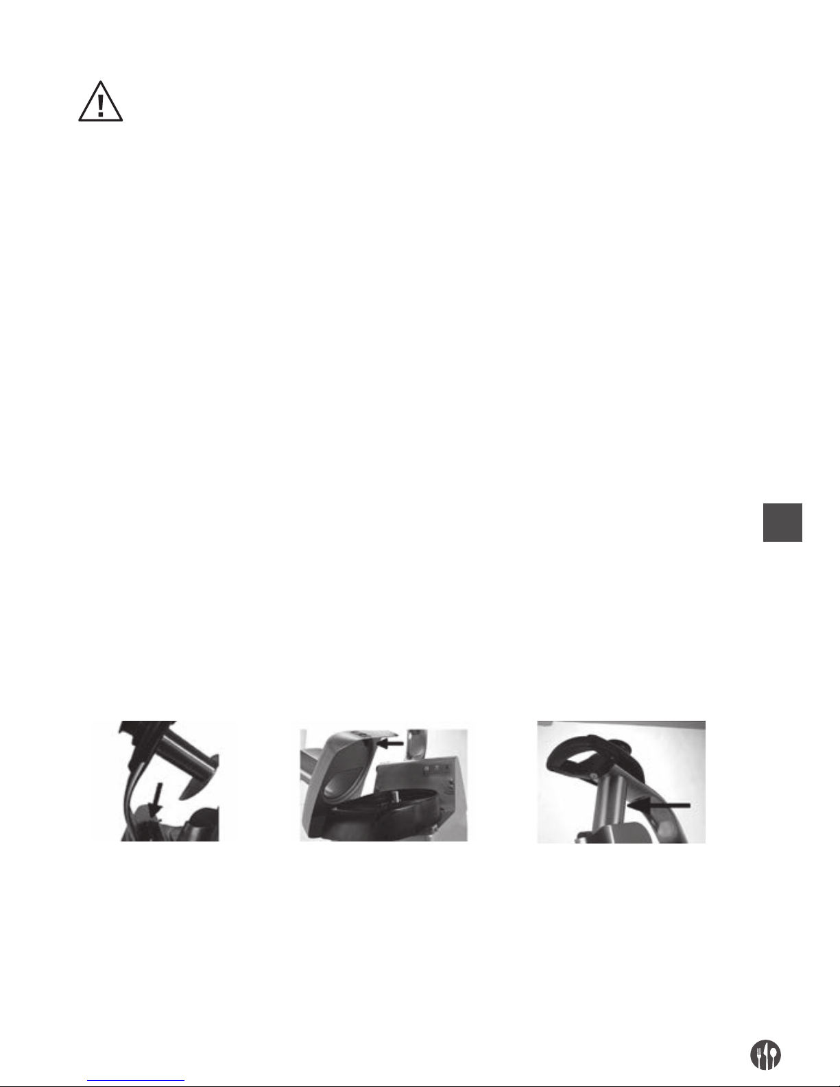
IT
85
DISPOSITIVI DI PROTEZIONE SULLA MACCHINA
Le protezioni ed i dispositivi di sicurezza della macchina non devono essere rimossi.
Qualora essi debbano essere rimossi per esigenze
di manutenzione straordinaria dovranno essere im-
mediatamente adottate misure atte a mettere in
evidenza e a ridurre al limite minimo possibile il
pericolo che ne deriva.
La rimessa in posto della protezione o del dispositi-
vo di sicurezza deve avvenire non appena siano cessate le ragioni che hanno resa necessaria la loro
temporanea rimozione.
Tutti i dispositivi di protezione e di sicurezza della
macchina, sia elettrici che meccanici, devono essere
mantenuti in condizioni di perfetta e costante efficienza.
Gli organi di trasmissione della macchina sono
completamente segregati per mezzo di protezioni
fisse che non permettono l’accesso a nessuna catena cinematica.
Per tutte le funzione di sicurezza comprendenti i sistemi di comando e controllo, sono stati utilizzati
componenti e principi di sicurezza ben collaudati.
GRUPPO PORTAUTENSILI:
1. Tenuto conto delle modalità di impiego della macchina e della sua destinazione d’uso, gli elementi
mobili sono sia segregati da ripari fissi, ripari mobili o altri dispositivi di sicurezza, posti a delle
distanze dai punti di accesso tali per cui non sono
raggiungibili punti pericolosi;
2. sul gruppo del manico e del pressore, è posto un
micro interruttore che arresta la rotazione degli
utensili quando è possibile accedere attraverso la
bocca di carico ;
3. la bocca di carico per tagliare, presenta una adeguata lunghezza: gli utensili risultano essere po-
sti a delle distanze dai punti di accesso tali per cui
non sono raggiungibili;
4. sul coperchio della zona superiore della macchina, è posto un micro interruttore che arresta la
rotazione degli utensili quando è possibile accedervi;
5. nella zona di scarico in corrispondenza della fuoriuscita del prodotto, la particolare conformazione del disco espulsore e dei dischi rotanti non
permette alla mano o parte di essa di raggiungere
gli organi in movimento e comunque parti con
punti pericolosi;
Manico del pressore
con micro interruttore
Coperchio superiore smontabile
con micro interruttore
Riparo fisso bocca di carico
per tagliare
Page 86
IT
86
CAP. 4. TRASPORTO, MESSA IN SERVIZIO ED USO
POSTAZIONI DI LAVORO E MANSIONI DEGLI OPERATORI
Come prescritto nel manuale delle istruzioni per
l’uso, la macchina è progettata per essere condotta
da un operatore addestrato ed edotto sui rischi resi-
dui, ma con le competenze, in materia di sicurezza,
degli addetti alla manutenzione.
La zona normale di lavoro dell’operatore è:
1. la zona laterale della macchina in prossimità delle bocche di carico (definita zona di carico) in condizioni normali di funzionamento per le operazioni
di carico manuale del prodotto alimentare e durante l’uso del pestello per convogliare il prodotto
alimentare entro il collo della macchina, con i ripari fissi e mobili in posizione chiusi e bloccati;
2. la zona anteriore della macchina in prossimità
della zona di scarico del prodotto alimentare in
condizioni normali di funzionamento per le operazioni di prelievo manuale del prodotto alimentare
depositato in apposito contenitore, con i ripari fissi e mobili in posizione chiusi e bloccati
OPERAZIONI PRELIMINARI DI PREPARAZIONE
STABILITÀ
La stabilità della macchina è progettata in modo
che, nelle condizioni di funzionamento previste, tenuto conto delle condizioni climatiche, è tale da consentirne l’utilizzazione senza rischio di rovescia-
mento, di caduta o di spostamento intempestivo.
Tenuto conto della conformazione e della sua posi-
zione, la macchina risulta essere intrinsecamente
stabile senza necessità di fissaggio al banco di la-
voro.
Tutti i piedini di appoggio posti sotto al basamento
devono appoggiare su una superficie solida, uniforme e ben livellata.
ALIMENTAZIONE ELETTRICA
L’allaccio dell’alimentazione elettrica, deve essere in conformità alla legislazione pertinente del paese in
cui viene usata.
L’alimentazione elettrica deve pertanto essere mantenuta in conformità alle seguenti prescrizioni tec-
niche:
1. l’alimentazione elettrica deve essere sempre del
tipo ed avere una intensità corrispondente alle
specifiche indicate nella targa della macchina. Se
vengono applicate tensioni eccessive, verranno
danneggiati irreparabilmente dei componenti,
2. deve essere previsto un dispositivo differenziale
coordinato con il circuito di protezione, rispettando la legislazione e le disposizioni legislative e
regolamentari vigenti nel paese d’installazione;
3. il cavo per l’alimentazione elettrica al di fuori
dell’involucro della macchina, deve essere fatto
passare negli spazi da Voi predisposti ed adeguatamente protetto;
4. se presente il conduttore di neutro (N) prima di
alimentare l’equipaggiamento elettrico, da parte
Vs deve essere garantita la sua continuità (collegato e disponibile).
5. prima di alimentare l’equipaggiamento elettrico,
da parte Vs deve essere garantita la sua continuità (collegato e disponibile) del conduttore giallo verde del circuito equipotenziale di protezione.
MONTAGGIO / SMONTAGGIO
Le operazioni di montaggio / smontaggio di qualsiasi organo della macchina vanno effettuate a macchina
ferma e con la spina scollegata dalla presa, ovvero con il dispositivo di sezionamento in OFF.
Page 87
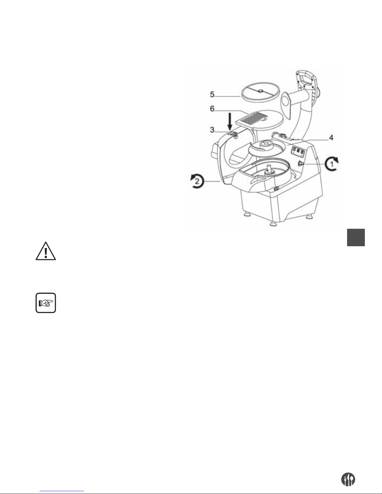
IT
87
Il montaggio degli utensili sulla macchina si svolge in varie fasi.
1. Ruotare il pomello di blocco (1) della cover superiore (2)
premere il pulsante (3) e con l’uso di entrambe le mani
ruotare la cover superiore (2)
2. Sul mozzo rotante, inserire per primo il disco
espulsore (4), accertandosi che i perni
di trascinamento presenti sul mozzo
si inseriscano nei fori esistenti sul disco;
3. Dovendo effettuare lavorazioni che richiedono
l’utilizzo di un solo disco, inserire sul mozzo
il disco rotante (5) al di sopra del disco
espulsore (4) (cfr. tabelle del capitolo n. 2)
4. Dovendo effettuare lavorazioni che richiedono
l’utilizzo contemporaneo di due dischi, inserire
sul mozzo rotante in sequenza i seguenti
elementi: (cfr. tabelle del capitolo n. 2)
1° - Disco espulsore (4)
2° - Disco fisso (6)
3° - Disco rotante (5)
5. Riposizionare la cover superiore (2)
ruotandola
6. Serrare il pomello di blocco (1) ruotandolo in
senso antiorario.
Dopo aver inserito i dischi a seconda delle esigenze di lavorazione, accertarsi del corretto aggancio a baionetta
degli stessi nel mozzo rotante.
Il disco espulsore DEVE ESSERE SEMPRE OBBLI-
GATORIAMENTE installato, affinché i dischi possano
operare in posizione corretta.
Per l‘ottimale utilizzo di tutti i tipi di dischi rotanti e
l’eventuale impiego contemporaneo dei dischi rotanti con quelli fissi, consultare le tabelle del capi-
tolo n. 2, recante tutte le possibili combinazioni funzionali.
Le attività di smontaggio si svolgono seguendo in modo a ritroso le fasi di montaggio precedentemente
descritte.
Page 88
IT
88
ROTAZIONE DEI DISCHI DI TAGLIO
Le operazioni di seguito indicate, devono essere
svolte dal manutentore della macchina (personale
specializzato nel settore della manutenzione elettrica delle macchine industriali).
Per macchine alimentate con tensione trifase (3 PE
AC 400V 50Hz), premere il pulsante di comando ad
azione mantenuta ”
”, e verificare il corretto sen-
so di rotazione dei dischi di taglio attraverso la bocca
di carico prodotto, confrontandolo con il senso indicato dalla freccia (senso antiorario) apposta sul coperchio della macchina.
Nel caso in cui vi sia una rotazione in senso opposto
a quello della freccia (senso orario), spegnere la
macchina staccando la spina, smontarla, scollegare
due conduttori di fase e invertirli di posizione.
DESCRIZIONE DEL FUNZIONAMENTO
I dispositivi di comando sono progettati e costruiti in
modo da essere tanto sicuri ed affidabili e resistenti
alle sollecitazioni normali di servizio, agli sforzi prevedibili ed agli agenti esterni. Sono inoltre chiara-
mente visibili, individuabili e contrassegnati da una
marcatura adatta. Di seguito sono riportati i principali dispositivi di comando:
TIPO / COLORE RIFERIMENTO / DESCRIZIONE
Pulsante / nero “O ” / Pulsante per il comando di arresto della macchina
Pulsante / bianco “ I ” / Pulsante per il comando di avvio della macchina con impulso
Pulsante / bianco “ ” / Pulsante per il comando di avvio della macchina ad azione mantenuta
SEGNALAZIONI
TIPO / COLORE RIFERIMENTO / DESCRIZIONE
Led fisso rosso Macchina alimentata con cover superiore chiusa e pressore abbassato
Led lampeggiante rosso Macchina alimentata con cover superiore aperta
Led fisso verde Macchina alimentata in funzione
Led lampeggiante verde Macchina alimentata con pulsante di avvio macchina premuto e pressore
sollevato all’abbassamento del pressore la macchina si avvia (led fisso verde)
AVVIAMENTO
L’avviamento con impulso della macchina è possibile
soltanto con una azione volontaria sul dispositivo di
comando previsto a tal fine: pulsante bianco “I” per
il comando di avvio della macchina.
ARRESTO
Per il comando di arresto azionare il pulsante nero
“O”. In caso di arresto momentaneo o prolungato,
prima di rimettere in funzione la macchina, devono
essere tolti tutti i prodotti alimentari entro la macchina: seguire le indicazioni relative allo smontaggio
del gruppo di taglio.
AVVIAMENTO AD AZIONE MANTENUTA
L’avviamento ad azione mantenuta della macchina è
possibile soltanto con una azione volontaria sul di-
spositivo di comando previsto a tal fine: pulsante
bianco ”
” per il comando di avvio della macchina.
Al rilascio del pulsante la macchina si arresta.
Page 89

IT
89
ASSENZA DI TENSIONE
In caso di interruzione dell’alimentazione elettrica o
se la macchina viene staccata dalla rete elettrica ,
quest’ultima potrà essere riavviata solamente se-
guendo la funzione di avviamento, dopo il ritorno
dell’alimentazione elettrica od il riallaccio alla
rete elettrica.
APERTURA DEL PRESSORE
Sollevando per il manico il pressore, la macchina si
arresta immediatamente per l’entrata in funzione
del micro interruttore di sicurezza. La macchina può
essere riavviata solamente abbassando il pressore
sino all’altezza che non permette l’introduzione delle dita verso la zona di taglio.
RIMOZIONE DEL COPERCHIO DELLA MACCHINA
Allentando o ruotando il pomello di blocco e rimuovendo il coperchio con entrambe le mani, la macchina si arresta immediatamente per l’entrata in funzione del micro interruttore di sicurezza. La
macchina può essere riavviata solamente riposizionando il coperchio della macchina e bloccandolo con
l’apposito pomello e eseguendo successivamente la
funzione di avviamento.
CONTROLLI E VERIFICHE PRIMA DELLA MESSA IN MOTO
VERIFICA / CONTROLLO MODALITÀ E RISCONTRI
Accertarsi che:
• Non vi siano sulla macchina,
entro le bocche di carico
ed in corrispondenza della
bocca di scarico zona di
fuoriuscita del prodotto
oggetti estranei
Controllo visivo delle parti indicate, per accertarsi dell’assenza di oggetti
o corpo estranei quali per es. utensili vari, stracci, etc… e che non vi sia
comunque il prodotto alimentare.
In caso di presenza provvedere alla loro rimozione.
Accertarsi della pulizia:
• delle parti interne della
macchina
• della zona di taglio, dei
dischi, della parte interna del
coperchio della macchina,
della bocca di scarico
• del pressore e del pestello
• della superficie esterna della
macchina
Tutti le superfici delle parti indicate, prima dell’impiego della macchina
devono essere controllate visivamente per accertarsi della loro pulizia.
Per il controllo visivo delle parti interne della zona di taglio, rimuovere
o il coperchio superiore.
In caso di presenza di muffe o altro tipo di sporcizia, provvedere alla procedura
di pulizia secondo le indicazioni di cui al capitolo 5.
Accertarsi dell’integrità:
• dei ripari fissi
• del coperchio superiore
di chiusura
• delle bocche di carico e di
scarico
• del pressore
• del corpo della macchina
Tutti i ripari fissi, etc.. devono svolgere la funzione per cui sono stati previsti.
Controllo visivo delle parti indicate per accertarsi della loro integrità nella
parte esterna della loro superficie.
Le parti devono essere comunque sostituiti ai primi segni di erosione o rottura
(cfr. Centro di Assistenza Autorizzato).
Page 90

IT
90
Accertarsi della funzionalità:
• delle parti del sistema
di comando / controllo
relative alla sicurezza;
• dei dispositivi di comando.
Tutti i dispositivi devono svolgere la funzione per cui sono stati previsti.
Comandare direttamente i dispositivi affinchè questi determinano la funzione
attesa.
Gli attuatori e tutte le parti devono essere comunque sostituiti ai primi segni di
erosione o rottura (cfr. Centro di Assistenza Autorizzato).
Accertarsi dell’assenza:
• di rumori strani dopo la
messa in moto
Durante l’accertamento della funzionalità dei dispositivi di comando, nel caso
in cui vi siano rumori strani, dovuti per esempio ad un grippaggio o rotture
meccaniche, arrestare immediatamente la macchina, ed attivare il servizio di
manutenzione.
Per qualsiasi tipo d’intervento o per la sostituzione
delle parti che risultano danneggiate, attivare il
servizio di manutenzione.
L’eventuale sostituzione deve avvenire con prodotti
originali del costruttore od almeno di qualità, sicurezza e caratteristiche equivalenti. Per approfondimenti contattare il Centro di Assistenza Autorizzato.
MESSA IN FUNZIONE
L’operatore della macchina, può mettere in funzione la macchina, seguendo in ordine le indicazioni sotto
riportate:
• Esito positivo dei controlli di cui alla operazioni
preliminari di preparazione,
• Esito positivo dei controlli di cui all’alimentazione
elettrica,
• Allaccio della spina in opportuna presa di corrente,
• Esito positivo dei controlli di cui al montaggio
(controllo posizionamento dischi, etc…),
• Esito positivo dei controlli di cui alla corretta rotazione dei dischi,
• Esito positivo dei controlli / verifiche prima della
messa in moto,
• Esito positivo dei controlli finalizzati ad accertare
il rispetto di tutte le condizioni di sicurezza,
• Posizionare il coperchio nella zona superiore dell
a
macchina e serrare o ruotare il pomello di blocco;
• Posizionare una bacinella di raccolta nella zona
anteriore della macchina in corrispondenza della
bocca di scarico del prodotto alimentare;
• osizionarsi nella zona sinistra della macchina ed
avviarla azionando il dispositivo di comando di
START “I”,
• Introdurre manualmente il prodotto alimentare
entro le bocche di carico a seconda delle esigenze
di lavorazione e spingerlo verso il basso / zona di
taglio o abbassando gradualmente il manico del
pressore o spingendolo con il pestello in dotazione, esercitando una leggera pressione per ottenere il miglior risultato operativo, senza sottoporre a sforzo anomalo gli organi di trasmissione.
Quando il pressore od il pestello giungono a fine
corsa, sollevarli e ripetere le operazioni sopra descritte proseguendo sino al completamento del
ciclo di lavoro,
• Al termine dell’introduzione del prodotto alimentare, ovvero quando dalla zona di scarico non fuoriesce più il prodotto, arrestare la macchina azionando il dispositivo di comando di STOP “O”.
SPEGNIMENTO
In successione, le operazioni di spegnimento devono seguire quanto di seguito indicato:
• prima dello spegnimento attendere la conclusione della fuoriuscita del prodotto alimentare dalla
bocca di scarico spingendo completamente verso
il basso il manico del pressore ed il pestello,
• arrestare la macchina azionando il dispositivo di
comando di STOP “O”,
• scollegare la spina della macchina dalla presa di
alimentazione,
• eseguire gli interventri di pulizia.
Page 91
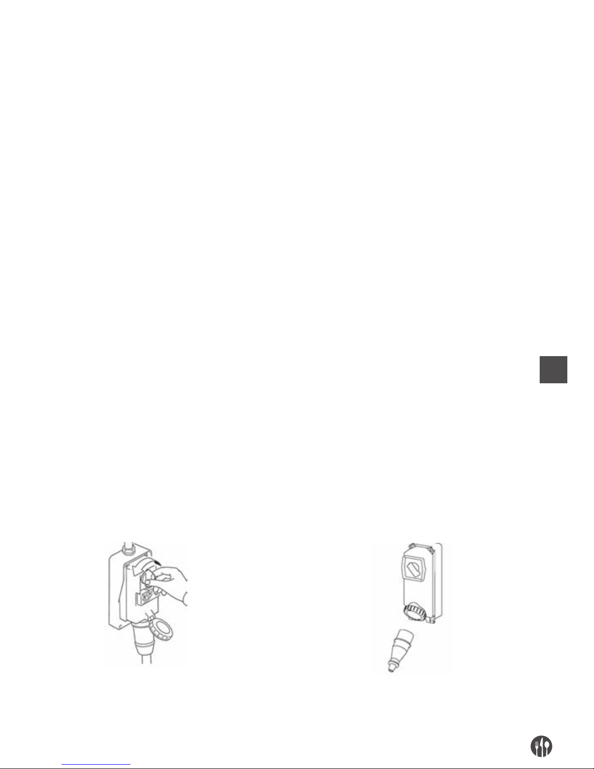
IT
91
SBLOCCO IN CASO DI INTOPPO
Durante la lavorazione, ovvero durante la rotazione dell’utensile, a causa:
• dell’introduzione di prodotti alimentari con parti
non omogenee,
• dell’introduzione di prodotti eccessivamente duri
e secchi, la macchina potrebbe bloccarsi.
La stessa situazione può determinarsi a seguito di
un guasto dell’alimentazione elettrica, ovvero quando la macchina viene arrestata con il prodotto alimentare al suo interno.
Per poter riprendere normalmente la lavorazione i dischi devono essere rimossi: lo smontaggio deve
seguire le prescrizioni precedentemente indicate.
CAP. 5. MANUTENZIONE, RICERCA GUASTI E PULIZIA
REQUISITI DEL MANUTENTORE
Con il termine “manutenzione” non deve essere inteso solamente il controllo periodico del normale
funzionamento della macchina ma anche l’analisi ed
il conseguente rimedio di tutte quelle cause che per
un motivo qualsiasi lo pongono fuori servizio. E’ assolutamente necessario che per le attività di manu-
tenzione, pulizia, sostituzione parti e ricerca guasti
effettuate dall’utilizzatore, questo compito sia affi-
dato a personale esperto, competente ed autorizzato
dal datore di lavoro.
Tutte le operazioni di manutenzione, pulizia e sosti-
tuzione parti, nessuna esclusa, devono essere tassativamente eseguite con la macchina completamente ferma ed isolata dalle fonti di alimentazione
esterne.
PRESCRIZIONI DI MANUTENZIONE
RIMOZIONE DEI RIPARI E/O DISPOSITIVI DI PROTEZIONE
Per alcuni interventi di cui al presente capitolo, è necessario rimuovere dalla loro posizione alcuni ripari fissi.
La rimozione può avvenire solo ad opera del manu-
tentore. Al termine degli interventi, detti ripari, devono essere riposti e bloccati nella loro originale
posizione, con i sistemi di fissaggio che erano previsti prima dell’intervento.
Il responsabile della manutenzione deve disattivare completamente la macchina, come tra l’altro di seguito riportato, prima di procedere all‘asportazione di un riparo fisso e/o alla sostituzione di un elemento.
ISOLAMENTO DALLE FONTI DI ALIMENTAZIONE ESTERNE
Prima di eseguire qualsiasi operazione manutenzione, pulizia e sostituzione parti, si devono sezionare ed
isolare le fonti di alimentazione esterne.
Posizionare a “zero” il dispositivo di protezione posto
a monte della linea d’alimentazione dell’equipaggiamento elettrico.
Disinserire il dispositivo di sezionamento generale
e provvedere a proteggere la spina con appositi sistemi.
Page 92

IT
92
RICERCA GUASTI O AVARIE E SBLOCCO ELEMENTI MOBILI
Di seguito sono indicati gli interventi per la ricerca guasti o avarie e sblocco elementi mobili che possono
essere svolti da manutentori.
TIPO POTENZIALE/I CAUSA/E MODALITÀ E RISCONTRI
Mancanza
tensione di rete
Black out generale
Contattare l’ente distributore dell’energia elettrica
Intervento di fusibili o magnetotermici
posti a monte della linea d’alimentazione della macchina
Dopo avere eliminato le cause che hanno
determinato l’intervento del dispositivo di
protezione, ripristinarlo. In caso di persistenza
del problema contattate un tecnico elettricista.
Interruzione di
funzionamento
Intervento del dispositivo di
protezione interno alla macchina
Contattate un tecnico elettricista: dopo avere
eliminato le cause che hanno determinato
l’intervento di un dispositivo di protezione,
ripristinarlo.
In caso di intervento di fusibili, sostituirli con
tipi dello stesso identico modello, taratura
e curva d’intervento.
Sollevamento del manico del
pressore (led verde
lampeggiante)
Sollevando il manico del pressore, la macchina
si arresta immediatamente per l’entrata in
funzione del micro interruttore di sicurezza.
Abbassare il pressore sino all’altezza che non
permette l’introduzione delle dita verso la zona
di taglio.
Rimozione del coperchio superiore
(led rosso lampeggiante)
Rimuovendo il coperchio superiore, la macchina
si arresta immediatamente per l’entrata in
funzione del micro interruttore di sicurezza.
Posizionare correttamente il coperchio
superiore e bloccarlo con l’apposito
pomello ed avviare la macchina.
Causa/e non identificabili Contattare direttamente il Centro di Assistenza
Autorizzato
La macchina
non funziona: i dischi
non ruotano o non
eseguono il taglio
correttamente
Mancanza tensione di alimentazione
(tutti i led spenti)
Controllare e ripristinare l’energia elettrica
Dispositivi di sezionamento su “O”
(tutti i led spenti)
Girare i dispositivi di sezionamento nella
posizione “ON”
Fusibili intervenuti o magnetotermici
non funzionanti
Fare sostituire i fusibili intervenuti, controllare
lo stato degli interruttori magnetotermici
Mancato funzionamento del pulsante
di marcia
Controllare l’efficienza del pulsante di “I”
ed eventualmente contattare direttamente
il Centro di Assistenza Autorizzato.
Micro interruttore guasto Contattare direttamente il Centro di Assistenza
Autorizzato
Dischi di taglio usurati o rovinati Contattare direttamente il Centro di Assistenza
Autorizzato
Cinghia di trasmissione lenta determina
anche emissione di rumore o cigolio
Contattare direttamente il Centro di Assistenza
Autorizzato
Page 93
IT
93
MANUTENZIONE STRAORDINARIA
Per gli interventi di manutenzione straordinaria,
conseguenti a rotture o revisioni o guasti meccanici
o elettrici (per es. il tensionamento delle cinghie di
trasmissione del movimento, etc…), è necessaria
una richiesta d’intervento irettamente al Centro di
Assistenza Autorizzato.
Le istruzioni relative alla manutenzione straordinaria, non compaiono nel presente manuale delle
istruzioni per l’uso e devono pertanto essere espli-
citamente richieste al fabbricante.
PULIZIA
E’ vietato pulire a mano gli organi e gli elementi in
moto.
Tutti gli interventi di pulizia devono essere messi in
atto solo ed esclusivamente, dopo aver scaricato la
macchina con il prodotto alimentare in lavorazione
ed averla isolata dalla fonte di alimentazione elettrica e di energia esterne.
La macchina, l’apparecchiatura elettrica ed i componenti a bordo macchina, non devono essere mai
lavati utilizzando acqua, tanto meno in forma di
getti di qualunque natura e quantità; quindi, senza
“secchio” né “gomma” né “spugna”. Non porre mai
direttamente la macchina nel lavandino o sotto il rubinetto.
La classificazione del livello di igiene della macchina e delle attrezzature associate, per l’uso previsto, è 2 (due):
macchina che, in seguito a una valutazione del rischio di igiene, è conforme ai requisiti delle norme internazionali
applicabili, ma richiede un disassemblaggio programmato per la pulizia.
FREQUENZA PERSONALE MODALITÀ
Al termine di ogni turno
di lavoro e comunque prima
dell’uso giornaliero
Operatore Tutte le superfici e le parti delle macchina destinate a venire a con-
tatto con il prodotto alimentare, ovvero, le zone alimentari (superficie interna delle bocche di carico e di scarico, il pressore, il pestello, la zona di taglio, i dischi rotanti e fissi, il coperchio superiore,
i ripari fissi) e le zone spruzzi (superficie esterna della macchina),
devono essere pulite e disinfettate con le modalità sotto riportate.
Per le attività di smontaggio del gruppo di taglio, vedere precedenti
descrizioni.
• Scrostare le superfici dagli eventuali residui di prodotto ali-
mentare (per es. con raschiatori di plastica);
• Pulire tutte le superfici della zona alimentare e zona spruzzi
con un panno morbido inumidito (non sgocciolante) con deter-
gente diluito in acqua calda (anche del comune sapone per piatti
va benissimo). Non lasciarli a mollo. Utilizzare prodotti specifici
per acciaio, questi debbono essere liquidi (non in crema o paste
comunque abrasive) e soprattutto non debbono contenere cloro.
Contro le sostanze grasse si può usare l’alcool denaturato.
• Risciacquare con acqua calda pulita e successivamente asciu-
gare tutte le superfici della zona alimentare e zona spruzzi con
un panno morbido che non perda peli.
• Le parti completamente in acciaio inox, possono essere lavate
anche in lavastoviglie.
• Il rimontaggio deve avvenire solo a seguito di una esigenza di
lavorazione, lasciare i pezzi avvolti in un panno morbido asciutto
che non perda peli.
Page 94
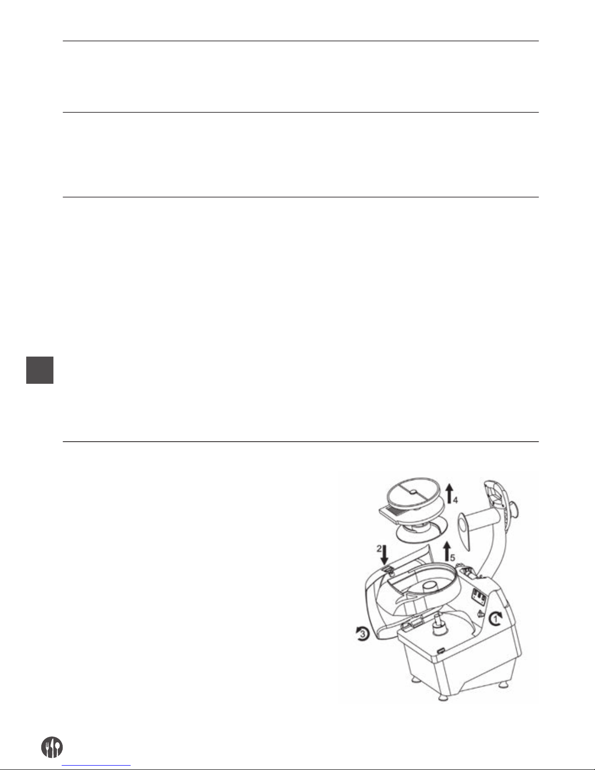
IT
94
PERIODI DI LUNGA INATTIVITÀ
• Durante i periodi di lunga inattività della macchina provvedere
a passare energicamente su tutte le superfici in acciaio (specialmente se inox) una panno imbevuto di olio di vaselina in modo da
stendere un velo protettivo.
COSE DA NON FARE PRIMA O DURANTE LA PULIZIA:
• Accedere agli elementi mobili senza essersi preventivamente accertati del loro arresto;
• Accedere agli elementi mobili senza averla fermata in sicurezza
garantita (bloccaggio nella posizione di zero dei dispositivi di sezionamento dell’alimentazione elettrica)
PRODOTTI DA NON USARE:
• aria compressa con getti verso le zone con depositi di farina ed in
generale verso la macchina;
• apparecchi a vapore;
• detergente che contengono CLORO (anche se diluiti) o suoi composti come: la candeggina, l’acido muriatico, prodotti per sturare
lo scarico, prodotti per la pulizia del marmo, decalcificanti in generale, etc … possono attaccare la composizione dell’acciaio,
macchiandolo od ossidandolo irreparabilmente. Le sole esalazioni dei suddetti prodotti possono ossidare ed in alcuni casi corrodere l’acciaio;
• paglietta, spazzole o dischetti abrasivi realizzati con altri metalli
o leghe (es. acciaio comune, alluminio, ottone, etc…) oppure
utensili che abbiano precedentemente pulito altri metalli o leghe,
che oltre a graffiare le superficie.
• detergenti in polvere abrasivi;
• benzina, solventi o fluidi infiammabili e/o corrosivi;
• sostanze impiegate per pulire l’argento.
SMONTAGGIO/MONTAGGIO PER LA PULIZIA
1. Ruotare il pomello di blocco (1) della cover superiore
premere il pulsante (2) e con l’uso di entrambe
le mani ruotare la cover superiore (3)
2. Estrarre dal perno rotante, i dischi di taglio
(rotante e fisso) e il disco espulsore (4),
rimuovere la vaschetta in plastica (5).
Page 95
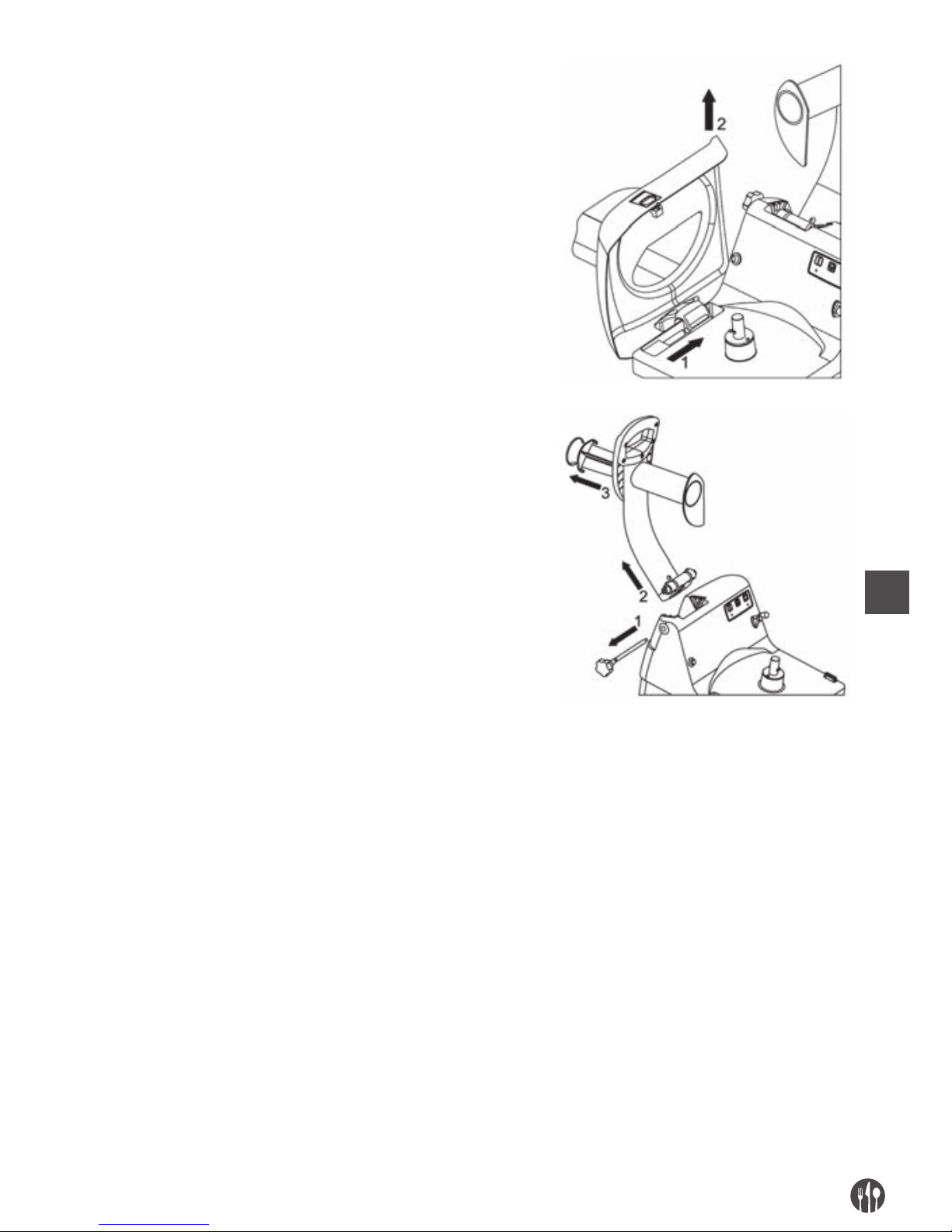
IT
95
3. Rimuovere (2) la cover superiore
sfilandola dal perno su cui ruota (1)
4. Posizionare il manico del pressore a fine corsa.
5. Sfilare il perno di sicurezza (1)
6. Sganciare dalla propria sede il manico
del pressore (2) sollevandolo verso l’alto
7. Ruotare e quindi estrarre il pestello (3).
CAP. 6. SMALTIMENTO
Nel caso in cui si decida di non utilizzare più la macchina perché obsoleta e/o irrimediabilmente guasta
o usurata al punto da renderne antieconomica la riparazione, occorre procedere alla sua messa fuori
servizio rendendola inoperante e priva di potenziali
pericoli. La messa fuori servizio deve essere affidata a personale specializzato ed attrezzato.
Al termine delle attività di smantellamento tutte le
targhette d’identificazione ed ogni altro documento
della macchina, deve essere distrutto.
La macchina può essere smaltita senza bisogno di ri-
durla
in pezzi minuti; è sufficiente scollegare i principali gruppi che la compongono e porli sul mezzo di
trasporto adibito alla rottamazione.
Provvedere al loro smaltimento operando in conformità alle norme vigenti, rivolgendosi agli organismi
preposti e/o ad imprese specializzate nella rottamazione industriale e/o nello smaltimento dei rifiuti,
affinchè avvenga la separazione tra materiale plastico, materiale metallico e componenti elettrici che
devono essere inviati a raccolte differenziate.
E’ obbligo del datore di lavoro essere a conoscenza delle leggi vigenti in merito nel proprio paese e ope-
rare in modo da ottemperare a tali legislazioni.
Page 96

IT
96
É vietato ed inoltre passibile di sanzioni, abbandonare la macchina e l’equipaggiamento elettrico nell’ambiente.
Il simbolo del cassonetto barrato riportato sulla
macchina indica che il prodotto alla fine della propria
vita utile deve essere raccolto separatamente dagli
altri rifiuti.
L’utente dovrà, pertanto, conferire la macchina giunta a fine vita agli idonei centri di raccolta differenziata dei rifiuti elettronici ed elettrotecnici.
CAP. 7. MATERIALI DI COSTRUZIONE
A seconda delle esigenze di funzionamento e di produzione, la macchina può essere costituita con diverse tipologie di
materiali di costruzione.
GRUPPO TIPOLOGIA MATERIALI
Acciaio inox Acciaio inox Plastica per Alluminio trattato
18/8 AISI 304 alimenti per alimenti
Corpo macchina •
Coperchio rimovibile superiore •
Bocche di carico •
Bocca di scarico •
Dischi rotanti • • •
Elementi di taglio dei dischi rotanti •
Dischi fissi • • •
Elementi di taglio dei dischi fissi •
Disco espulsore •
Pestello •
Pressore •
Cover superiore •
Vasca di taglio •
Page 97

IT
97
Page 98

RU
98
ОГЛАВЛЕНИЕ
ГЛАВА
1. УСТРОЙСТВО РУКОВОДСТВА ............................................................. 99
ГЛАВА
2. ОБЩИЕ ДАННЫЕ И ХАРАКТЕРИСТИКИ ......................................... 100
ГЛАВА
3. ИНСТРУКЦИИ ПО ТЕХНИКЕ БЕЗОПАСНОСТИ ............................... 104
ГЛАВА
4. ПЕРЕВОЗКА, УСТАНОВКА И ИСПОЛЬЗОВАНИЕ ............................ 106
ГЛАВА
5. ТЕХНИЧЕСКОЕ ОБСЛУЖИВАНИЕ, ВЫЯВЛЕНИЕ НЕПОЛАДОК
И ЧИСТКА........................................................................................... 111
ГЛАВА
6. УТИЛИЗАЦИЯ .................................................................................... 116
ГЛАВА
7. ИСПОЛЬЗОВАННЫЕ МАТЕРИАЛЫ .................................................. 117
Page 99

RU
99
ГЛАВА. 1. УСТРОЙСТВО РУКОВОДСТВА ЦЕЛЬ РУКОВОДСТВА
ВАЖНОСТЬ РУКОВОДСТВА
Данное руководство по использованию считается неотъемлемой частью оборудования.
• необходимо хранить руководство в течение
всего периода использования оборудования.
• руководство должно прилагаться к оборудованию в случае его передачи.
• помимо всех сведений, необходимых пользо-
вателю, руководство содержит (по разделам)
электрические схемы, которые необходимы
для технического обслуживания и возможного
ремонта.
ЦЕЛЬ РУКОВОДСТВА
Целью руководства по использованию является
предоставление заказчику всей информации,
необходимой не только для правильного использования поставленного оборудования, но и для
как можно более надежной и автономной работы
с ним.
Кроме того, данное руководство составлено с це-
лью предоставления указаний и предупрежде-
ний, которые позволят изучить поставленное
оборудование и понять принципы и пределы его
функционирования. В случае возможных сомнений обращаться в Уполномоченный Центр Обслуживания.
КОМУ ПРЕДНАЗНАЧЕНО
Данное руководство по использованию, поставляемое в одной копии вместе с оборудованием,
является его неотьемлемой частью и предназначено как операторам, так и квалифицированным
специалистам, занимающимся его установкой,
использованием и техническим обслуживанием.
Ответсвенный за технику безопасности заказчика и другие работники, которым предназначе-
но оборудование, должны изучить данное руководство по использованию, чтобы выполнить все
технические и организационные указания.
ОТВЕТСТВЕННОСТЬ
• В случае повреждения или утери данного руководства, можно запросить его копию в
Уполномоченном Центре Обслуживания.
• Данное руководство соответствует состоянию
техники на момент создания оборудования;
производитель оставляет за собой право обновлять продукцию и, следовательно, последующие издания руководства, не обновляя при
этом предыдущую продукцию и издания, за
исключением особых случаев, касающихся
здоровья и безопасности людей.
• Сле дует при дат ь особое знач ение остаточным
рискам, присутствующим на оборудовании, и
указаниям, которых должны придерживаться
работники.
• Производитель несет ответственность за обо-
рудование в его первоначальном состоянии.
• Производитель не несет ответственность за
повреждения, вызванные несоответсвующим
или неправильным использованием оборудования и документации, или за повреждения,
вызванные нарушением норм, невнимательностью, неосторожностью, неумением и невыполнением предписанных норм со стороны работодателя, оператора или наладчика, и за
любые возможные повреждения, вызванные
неправильным и/или несоответствующим использованием.
• Производитель не несет ответственность за
последствия использования нефирменных запасных частей или запасных частей с неравноценными характеристиками.
• Производитель несет ответственность только
за информацию, приведенную в оригинале
руководства на итальянском языке.
• Несоблюдение указаний, содержащихся в данно
м руководстве, ведет к немедленному
прекращению гарантии.
Page 100
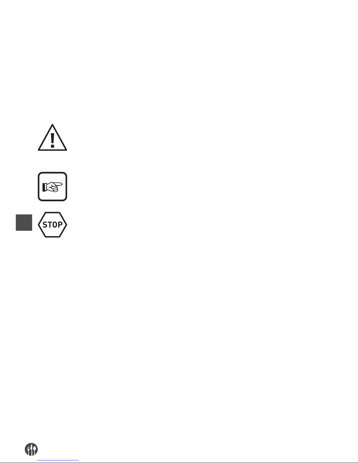
RU
100
Ответственные лица предприятия, отвечающие
за рабочую деятельность, в сфере соответствующих полномочий и компетенций должны:
• Применять предусмотренные меры безопасности;
• Уведомлять операторов об определенных рисках, которым они подвергаются, и доводить
до их сведения основные нормы техники безо-
пасности;
• Требовать от всех операторов исполнения
норм техники безопасности и использования
средств защиты, предоставленых в их распоряжение;
• Этим должны заниматься одновременно несколько работников.
ЗНАЧЕНИЯ СИМВОЛОВ
Далее приведены значения и определения символов, которые используются в данном документе.
ОПАСНОСТЬ
Указывает на опасность, которой могут подвергаться лица, работающие на оборудовании и находящиеся вблизи его, в связи с чем данные операции должны выполняться
с соблюдением действующих норм техники безопасности и указаний, приведенных
в данном руководстве.
ОСТОРОЖНО
Указывает на наличие полезной информации и/или дополнительных рекомендаций
и/или предосторежений, связанных с выполняемой операцией.
ВНИМАНИЕ
Указывает на операцию, которую следует выполнять внимательно во избежание повреждений оборудования.
ГЛАВА. 2. ОБЩИЕ ДАННЫЕ И ХАРАКТЕРИСТИКИ
ПРЕДНАЗНАЧЕНИЕ И ОСНОВНЫЕ ЧАСТИ
Овощерезка, в дальнейшем называемая «машина», предназначена для того, чтобы нарезать на
ломтики, на кубики, натирать свежие фрукты и овощи всех известных типов (цуккини, морковь,
сельдерей, картошку, перец, помидоры и т.д.) и другие с аналогичной консистенцией.
Машина состоит из электрического мотора,
включенного единым сплавом (базовый корпус
машины), в котором вал двигателя подсоединен к
режущему инструменту посредством специальных приводных ремней.
Пищевой продукт, загружаемый вручную, может
быть помещен:
1. в загрузочное отверстие для нарезки на куби-
ки и на соломку, расположенное в верхней левой части машины, и, также вручную, посредством воздействия на рукоятку прижимного
устройства, пищевой продукт проталкивается
в зону резки. Необходимо загружать продукт
небольшими порциями, в противном случае,
при опускании рукоятки прижимного устрой-
ства не произойдет запуск машины, благодаря
защитному микровыключателю, расположенному в блоке прижимного устройства;
2. в загрузочное отверстие для резки, располо-
женное в верхней правой части машины, и,
также вручную, и при помощи песта продукт
проталкивается в горловину машины в направлении зоны резки. Пест выполнен из
пластмассы и годен для работы с пищевыми
продуктами.
Загрузочные отверстия для нарезки на кубики и
на соломку и для резки расположены на крышке,
закрепленной на машине посредством специальной кнопки: на машине имеется защитный
микровыключатель, определяющий правильное
 Loading...