

Henderson TRACKED Installation Instructions Manual
Secure the cast alloy roller brackets over the top
weatherstrips using 38mm x 8mm self-tapping screws
A
using the 3 large holes in the bracket. Ensure that the
roller brackets are aligned squarely with the top of the
door and insert the roller spindles into the roller brackets.
When all installation steps have been completed, the
rollers must still be able to be turned by hand.
Similar to artwork as figure 2 tracked single unframed
GRP doors - but remove head of fastener shown securing
the top weatherstrip and outer profile of roller bracket
base is changed - photograph available
‘C’ tracks are supplied preassembled to the front track brackets.
Support the rear end of the ‘C’ track
and place the front over the roller as
shown.
Using 38mm x 8mm screw
A, fit front
track brackets to the side frames, first
through the top vertical slotted hole
as shown and then through the lower
vertical slotted hole. Note - a third
fastener is added to each track
bracket later (see step 5).
Ensure the roller spindle clearance
between the cast roller bracket and
spindle washer is 3mm as shown.
Note: The rollers are not required to
support the weight of the door. It is
important that the rollers can be
moved by hand once the temporary
door supports used in step 2 are
removed.
Slide the adjustable ceiling support over the rear of
the ‘C’ tracks and raise the tracks. Ensure the ‘C’
tracks are parallel and angle downward from the
face of the door to the back of the garage by
approximately 53mm
Secure ceiling support and fixing straps into the
ceiling using fixings
B, C, D and G (not required if
secured to timber). Ensure ‘C’ tracks are square to the
opening. Diagonal measurement of the tracks from
corner to corner should be equal. Check the position
of the roller at the front of the track. Position the front
track brackets to provide a small clearance at the
bottom of the roller (1mm). Now fix 50mm x 8mm
screws
A in the remaining bottom hole of the ‘C’
track front bracket (see step 3).
Insert the track roller stop into the end of the track. Fix
using M8 x 40mm hexagonal slotted machine screw
C, nut D and washers E and F.
Important: Correctly fitted ‘C’ tracks will be rigid and
parallel and will not require intermediate supports.
The pivot blocks are handed. Line up the edge of the pivot block with the inside edge of the frame
leg, ensuring there is a gap of approximately 3mm between the top of the pivot block and the
bottom edge of the top weatherstrip guide, as shown.
Secure using two 38mm x 6.3mm screws
B through the holes provided. Repeat the holes provided.
Repeat for the other side.
Slide the middle weatherstrip under the rebate at the bottom of the pivot block, ensuring that the
rubber edge overlaps the door edge and the plastic edge is level with the inside edge of the pivot
block. Secure to the frame through the top hole in the weatherstrip using a tack
T. Repeat for the
other side.
Before installation ensure a suitable good quality
frame is fitted, ideally hardwood or softwood timber
76mm x 76mm.
Timber of different sizes may be used:Head 38mm minimum
Side 70mm minimum
The frame may be between or behind the reveals,
must be secure, square and upright. It is important
that the back surfaces of the frame are flush.
Note: All doors include the necessary clearances.
You should carefully remove the fittings pack and other
loose items attached to the door.
Remove the protective wooden batten from the bottom of
the door (where fitted). Handle the door carefully to avoid
damage.
At this stage ensure that all equipment and fittings are
inside the garage.
Position the door within the frame, ensuring that the top
weatherstrips are flush against the frame legs.
Temporarily secure the door in position. Place 2 x 10mm
packers in the top of the door, lift and wedge the door on
both sides until it is in contact with the packers at the top.
Ensure that the following clearances are established
between the door and frame.
Top = 10-13mm
Each Side (Premier Door) = 8 -11mm
Each Side (Castle Door) = 10-13mm
Bottom = 10-15mm
Note: If you are short of any of the items mentioned, please contact your supplier.
Familiarize yourself with the terms for the door components before starting the installation. The door and
components must be installed by suitably trained and qualified persons, in accordance with the instructions
provided. If in doubt contact a professional installer. It is important that the installation does not deviate from the
instructions provided such that all requirements of EN 12604 and EN 12453 are met and if necessary verified
(from May 2004). Once installed the door should be labeled in accordance with EN 13241 (from May 2004).
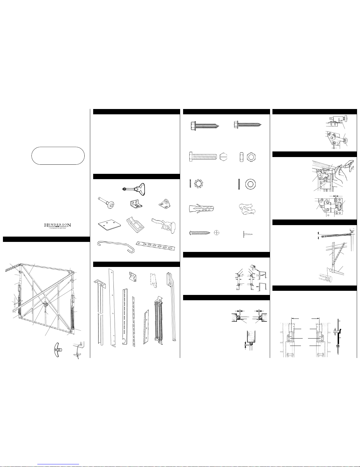
UNFRAMED TRACKED DOOR
CONTENTS OF THE FITTING / PRE PACK
CONTENTS OF THE GEAR PACK
IMPORTANT
Inner handle
2 off
NOTE: Two inner handles are provided to make
the door easier to lift during transit. They are
attached by ropes to the bottom sides of the door
chassis and should be removed once the door is
secured in position. They will be used in step 12.
Check that all contents are included in the packs and that the door size is correct for the opening
(see label on side of door - the label refers to the size of opening and not size of door).
The following parts are supplied separately and must be checked before starting installation: -
Gear Pack ‘C’ track assembly 1 off - see contents list
Weatherstrip pack 1 off - see contents list
Fittings pack 1 off - see contents list
Pre-Pack 1 off - see contents list
Installation is carried out from inside the garage. Ensure that you have adequate lighting and that
all tools and fittings are inside the garage BEFORE you start.
Ensure you have the outer handle with you before leaving the garage during installation. Whilst
operating the door be aware of the area it moves through. Keep people and objects out of the
way. When manually operating the door, control the leading edge of the door by hand throughout
the opening and closing cycle. When the door is in the open position, always ensure it is fully
open/as far back as possible.
Ensure that good safety practices are employed during installation. Use good quality tools and take
appropriate care if using any electrical equipment. Always check for dangerous features in the
workspace such as sharp edges, protrusions or concealed or damaged electrical wiring
FIT THE ROLLER BRACKETS AT THE TOP WEATHERSTRIP
3
ATTACH THE’C’ TRACKS
4
ALIGN THE ‘C’ TRACKS
5
LOCATE PIVOT BLOCKS & MIDDLE WEATHERSTRIPS
6
CONTENTS OF FIXINGS PACK
Installation Instructions
For
TRACKED
Unframed Single
GRP Garage Door
(where the door is to be fitted to a timber garage door frame)
Always read the care and maintenance label thoroughly.
Part No. 002440
Issue No. 04 December 2004
PC Henderson Limited
Durham Road, Bowburn, County Durham DH6 5NG
Telephone: 0191 377 1441 Fax: 0191 377 2972
H
ENDERSON
Roller bracket
(each side)
’C
’ track
assembly
(each side)
Door bracing
Arm
assembly
(each side)
Spring
assembly
(each side)
Spring anchor
bracket
(each side)
Slam-latch keep
(each side)
Slam-latch
bracket
(each side)
Pull rope
Door
bracket
(each side)
Ceiling
support
Strap
Top
weatherstrip
(each side)
Middle
weatherstrip
(each side)
Inside handle
Lock arms
Slam latch
bracket
(each side)
Keys (attached
to lock body)
Note: The door bracing differs with
each door style
Illustration shows pattern for vertical and
horizontal type panels.
Outer handle - 1 off
(includes screw and
washer)
Washers - 6 off
Roller spindle
- 2 off
Door bracket
- 2 off
Slam-latch keep
- 2 off
Strike plate - 2 off Pivot block - 2 off
(One Left hand and one right hand)
Stop - 2 off
Adjustment strap - 2 offHook - 2 off
Door arm
Assembly
- 2 off
Middle
weatherstrip
- 2 off
Bottom
weatherstrip
- 2 off
Spring Anchor bracket
- 2 off
Roller bracket
- 2 off
Ceiling
support
- 2 off
’C‘ track assembly
- 2 off
(not boxed)
Strap
- 2 off
Spring
Assembly
- 2 off
ITEM A - Qty - 24
38mm x 8mm self-tapping screw
Pilot hole diameter - 4.5mm
USE IN STEPS - 3,4,5,7 and 8
ITEM B Qty - 8
38mm x 6.3mm self-tapping screw
Pilot hole diameter - 4.5mm
USE IN STEPS - 5 and 6
ITEM C - Qty - 4
M8 x 40mm hexagonal slotted
machine screw
USE IN STEP - 5
ITEM D - Qty - 12
M8 steel nut
USE IN STEP - 5
ITEM E - Qty - 12
M8 shakeproof washer
USE IN STEP - 5
ITEM F- Qty - 2
M8 plain washer
USE IN STEP - 5
ITEM: G QTY: 8
Rawlplugs. Pilot 8mm diam.
USE IN STEP - 5
ITEM H - Qty - 2
Saftey fasteners
USE IN STEP - 6
ITEM T - Qty - 14
Tack
USE IN STEPS - 6,8 and 9
ITEM I - Qty - 4
32mm x 8g Posidrive screws
Pilot 1.5mm diam.
USE IN STEP - 11
SHOWN ACTUAL SIZE
CHECK EXISTING FRAME DIMENSIONS
1
PLACE THE DOOR IN POSITION
2
Reveal
Frame
Door
Between
reveals
Behind
reveals
70mm min.
Weatherstrips
13mm max.
13mm
13mm max.
Cast roller
bracket
Transit
bracket
Cast roller bracket
Spindle
washer
Front track
bracket
’C’ track
’C’ track
3mm
Stop
’C’ track
Ceiling
support
Fixing strap
53mm
Inside of frame
3mm
L/H R/H
Middle
weatherstrip
Middle
weatherstrip
Pivot
block
Pivot
block
top
weatherstrip
guide
top
weatherstrip
guide
Cast roller
bracket
Roller
Top weatherstrip
If you experience any problems with the operation of your door firstly check the frame and door
installation as shown in steps 1 to 14 and ensure all installation steps have been followed correctly.
PROBLEM SOLVING
Problem The door sticks out from the frame at the bottom.
Solution 1 Ensure roller spindles can move freely in the ‘C’ tracks. If necessary, reposition ‘C’
track front brackets. See step 4.
Solution 2 Ensure there is a 3mm gap between the top weatherstrip guide and the pivot
block. See step 6.
Solution 3 Release the spring tension and straighten the frame leg. Fasten the frame to the
wall above the jamb bracket and below the spring anchor bracket and secure the
base to the floor using a suitable bracket.
Problem The door ‘kicks across’ to one side when open.
Solution Ensure the ‘C’ tracks are parallel. Measure diagonally from corner to corner. The
distance should be equal. Re-position if necessary. See step 5.
Problem The handle is stiff to turn.
Solution Apply a drop of lubricating oil to the handle bush - see step 12.
The door must be dismantled with care. Always ensure that the structure is well supported during
dismantling and that parts are not allowed to fall or pivot in an uncontrolled manner.
Start from inside the garage and ensure that all necessary lighting, tools and personnel are available.
The door should be opened and propped securely in the opening. The door springs can be carefully
removed by disengaging from the adjustment strap (see note 10 for reference). The springs,
adjustment straps and hooks can now be detached from the door. The door leaf should now be
carefully moved to the closed position and the door and frame should be secured with supports.
The gear arms can now be detached from the frame - taking care to lower the arms to the floor after
removal of the fixing screws (see note 7 for reference)
Release the ‘C’ tracks from the ceiling supports and lower towards the front of the door. Remove the
ceiling track supports (see note 5 for reference)
Detatch the ‘C’ track front brackets from the frame taking care to support the ‘C’ tracks which will
then detach from the opening (see note 4 for reference)
Remove the spring anchor bracket and strike plates by removing the local fasteners (see note 8 for
reference). Remove the pivot blocks (see note 6 for reference)
Remove the top slam latch keeps to release the engagement of the slam latch (see note 11 for
reference).
The door can now be carefully handled; the prop supports removed and the door will release from
the opening. Ensure that hands will not come into contact with any sharp edges and wear gloves if
necessary. Always take care when handling heavy items.
Carefully remove the lower weatherstrips and tacks ensuring that they are not left in the vicinity where
they can be trodden or driven upon.
Dispose of all unwanted parts in accordance with best practices and legislation.
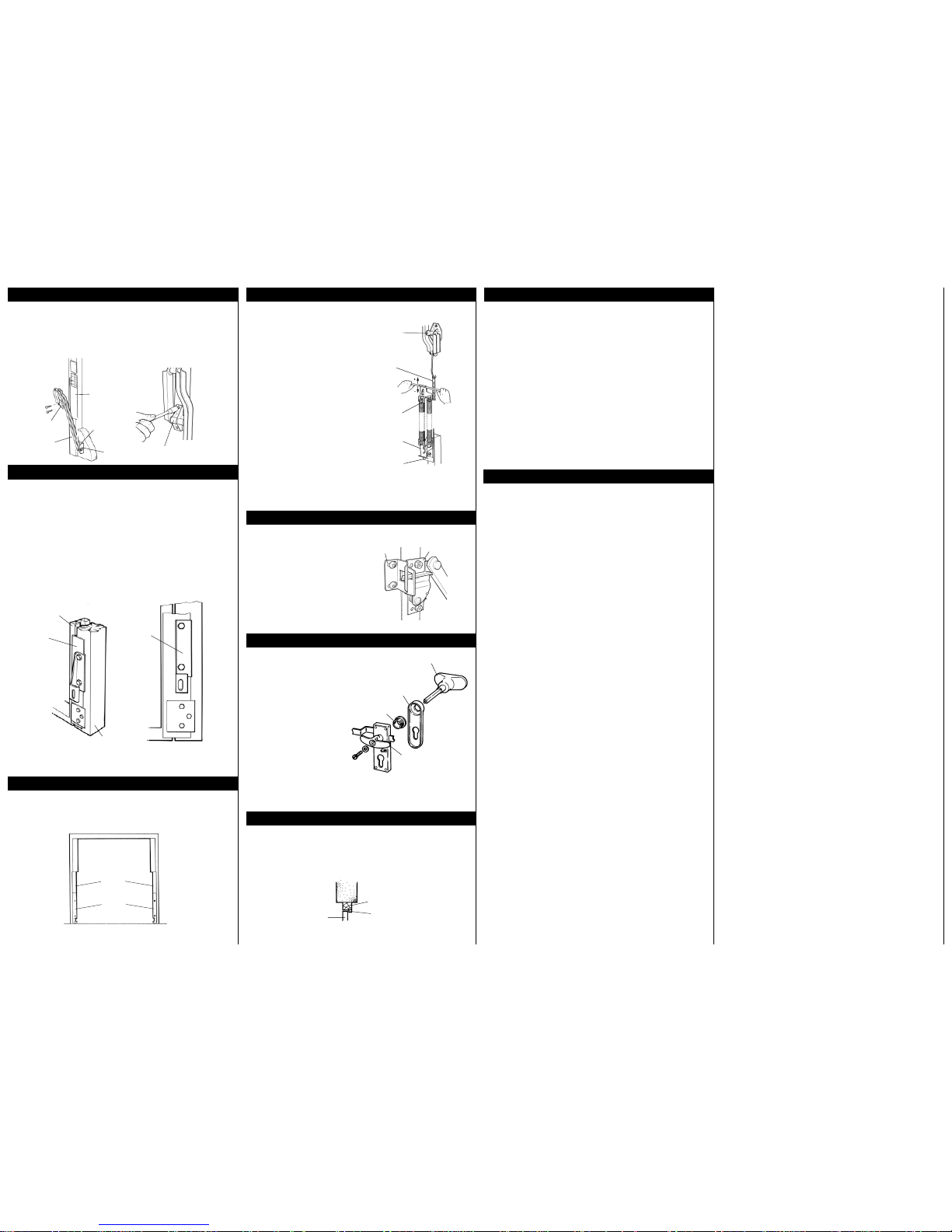
Ensure that the pivot block and middle weatherstrip are correctly positioned. Carefully mark through
the plastic weatherstrip to position the pilot holes for the jamb bracket. Pilot drill, avoiding damage to
the weatherstrip, and secure the jamb brackets and gear arms using the 38mm x 8mm screws
A.
Utilizing the pilot holes provided in the door, attach both bottom door brackets, using the holes
furthest from the edge of the bracket with 38mm x 8mm screws
A. Locate the door arms into the
bottom door brackets and secure using safety fasteners
H, fully tighten bottom door brackets
For Doors 2101 mm high and above.
Butt the bottom weatherstrip against the middle weatherstrip. Align and flatten the bottom weatherstrip
against the frame leg and secure using one or more tacks
T. Use the lower holes as templates to pilot
drill five holes 4.5 mm diameter in the frame. Position the spring anchor bracket over the weatherstrip
and secure using 2 off 38mm x 8mm self tapping screws
A. If the weatherstrip is excessively long the
excess may be removed using scissors. The strike plate should be positioned on top of the weatherstrip
to align with the three holes and fastened with 3 off 38mm x 6.3mm self tapping screws
B.
For Doors 2100 mm high and below.
Here a longer strike plate is used and the spring anchor bracket is secured on top. Align and flatten
the bottom weatherstrip against the frame leg and secure using one or more tacks
T. If the
weatherstrip is excessively long the excess may be removed using scissors. Use the lower holes as
templates to pilot drill two holes 4.5mm diameter in the frame. Position the strike plate over the
weatherstrip and locate the spring anchor bracket provided onto the strike plate. Secure using 2 off
38mm x 8mm self tapping screws
A.
Ensure that the weaterstrips have been positioned correctly and that they lie flat against the frame
legs. Using tacks
T secure the unsupported of the section of the weatherstrips to the frame leg. The
tacks should be hammered into position carefully.
Remove the items being used to temporarily
secure the door in position. Grip the door
and simultaneously release the catches by
pulling the lock arms. Slowly and carefully
open the door and carefully locate a prop to
hold the door safely while the springs are
fitted.
Locate the spring carrier onto the hook on
the spring anchor bracket, ensuring that the
hook has located properly as shown.
Using a suitable lever, carefully lift the top
part of the spring assembly and locate the
hook into one of the slotted holes on the
adjusting strap as shown. Ensure that the
same slotted hole is used on both sides of the
door.
Support the leading edge of the door leaf
and carefully remove the door leaf support
prop. Guide the door towards the closed
position until the tension of the springs
supports the door. Ideally the door will be
well balanced and should find a natural ‘at
rest’ position at about 2/3 of the way down.
If necessary re-support the door leaf and
adjust the spring tension as necessary (move
up the slotted plate to increase the spring
force and down the slotted plate to reduce
the spring force).
Position the slam latch keep to correctly engage
over the slam latch. A 2mm clearance should be
provided between the adjacent faces of the slam
latch keep and the slam latch bracket to allow free
movement of the door leaf at opening. Pilot drill as
recommended and secure the slam latch keep in
position using two 32mm x 8 gauge posidrive
screws
I. Fit the second keep.
The bottom slam latches locate against the lower
metal strike plate and do not require slam latch
keeps to be fitted.
With the lock supported on the inside,
push the handle bush into position from
outside and fit the fascia by inserting
the fixing lugs into the holes until they
‘snap-in’. Remove the screw and
washer from the outer handle and pass
the handle through the lock as shown.
Fit one of the inner handles and secure
using the screw and washer just
removed. Check the operation of the
handle and lock mechanisms.
The second inner handle should now
be attached with the rope below the
lock body, on the door bracing. Thread
the rope through the hole provided and
knot securely to make a ‘rope pull’.
Note: The fascia is not supplied for the
Merlin, Doric, Durham and Victoria
steel doors and is supplied pre-fitted
to timber doors.
When the installation is complete, apply a small amount of oil to the pivot points.
When installing into a timber frame of the recommended size, fit a 25mm x 25mm weather beading
to the outside of the frame head as shown.
SECURE THE GEAR ARM JAMB BRACKET TO THE FRAME
7
FIT THE SPRING ANCHOR BRACKETS & STRIKE PLATES
8
SECURE THE BOTTOM WEATHERSTRIPS
9
DISMANTLING
15
TROUBLESHOOTING
14
FIT THE LOCK
12
COMPLETING THE INSTALLATION
13
FIT THE DOOR SPRINGS
10
FIT THE TOP SLAM LATCH KEEPS
11
P C Henderson Limited Durham Road, Bowburn, County Durham DH6 5NG
Telephone: 0191 377 1441 Fax: 0191 377 2972
Part No. 002440 Issue No. 04 January 2004
Outer handle
Handle bush
Inner handle
Fascia
Middle
weatherstrip
Bottom door
bracket
Safety
fastener
Door arm
assembly
Jamb bracket
Jamb bracket
Lower
weatherstrip
Door chassis
Frame leg
(right hand side shown)
Spring anchor
bracket
Middle
weatherstrip
Bottom
weatherstrip
Jamb bracket
Adjusting
strap
Spring anchor
bracket
Spring carrier
Upper spring
assembly
Slam-latch
bracket
Slam-latch keep
Frame head
Weatherbeading
Door
 Loading...