

Henderson SHUTTER SLIDE System Manual
SHUTTER SLIDE
Single Panel or Sim Action - Manual Operation
Fitting Instructions
No. of Panels
Type of
System
Min. Panel
Width
Max. Panel Height
Panel Thickness
Range
Max. Panel
Weight
1 or 2* Manual 400mm 3000mm 35-48mm 120kg
*For 2 door applications (1+1) please use these instructions in conjunction with the Shutter Slide SIM Action Fitting Instructions
PANEL SPECIFICATION
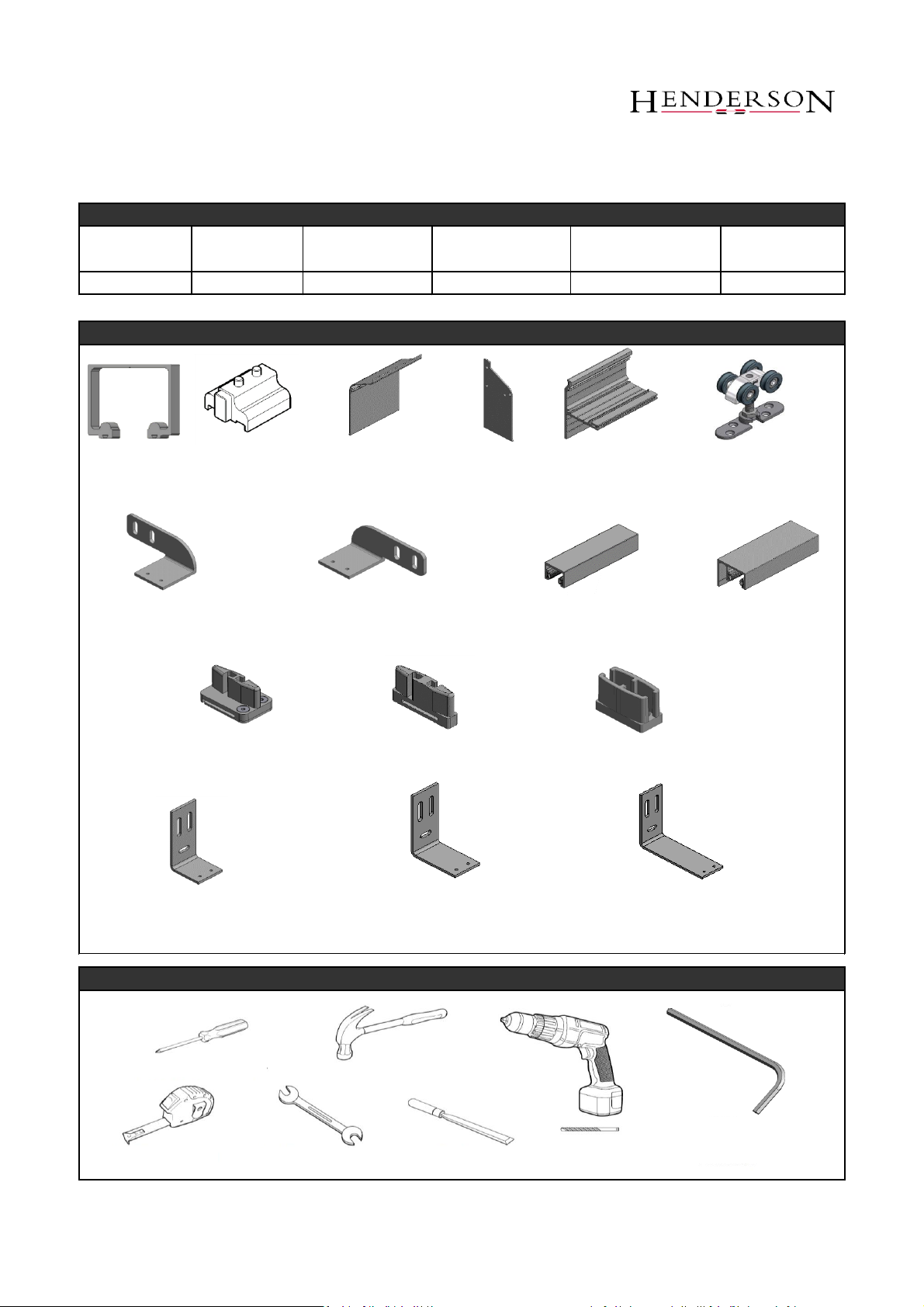
SYSTEM COMPONENTS
TOOLS REQUIRED
120 Track (x1)
HH4/AN Track
Stop (x2)
WP50F Fascia (x1)
WP50/EC End
Cap (x2)
WP50T Wall Fixing
Profile (x1)
51/120/SS Hanger (x2) or
56/120/SS Hanger (x2)
GSS/SBK10 Guide (x1)
GSSUR
Channel (x1)
GSSULR Channel
(x1)
GSS/MK40 Fixing Plate (x1)
GSS/MK60 Fixing Plate (x1)
GSS/MK100 Fixing Plate (x1)
Phillips Screwdriver
Tape Measure
Drill
Hammer
2, 3, 4 & 5mm
Allen Keys
13mm Spanner
Chisel
Components vary depending on specification
GSS/SSK10 Guide (x1)
GSS/SL Guide (x1)
GSS/RH Offset Angle
Plate Right (x1)
GSS/LH Offset Angle
Plate Left (x1)
OR
OR
OR
OR
OR
OR
Page 1
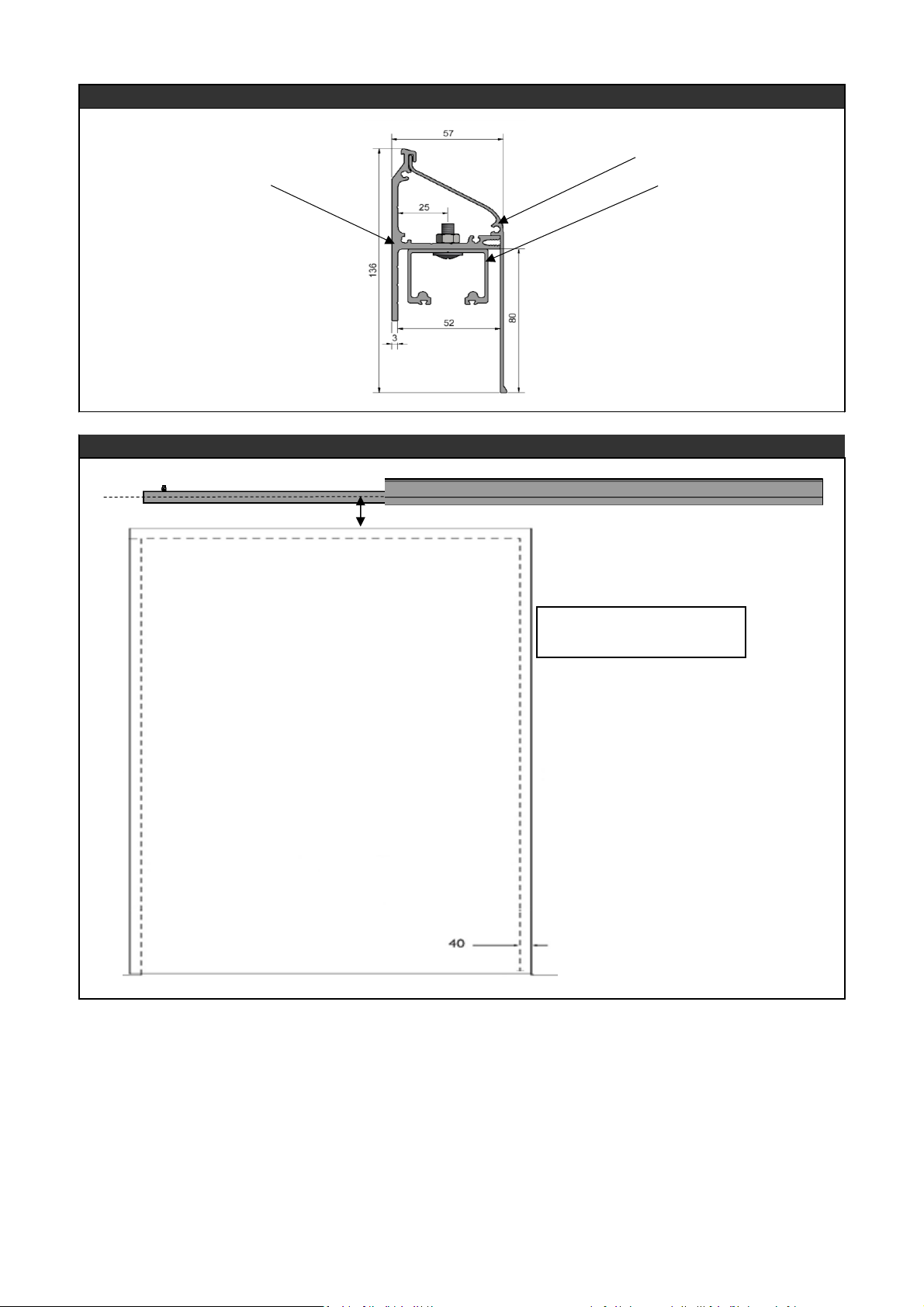
TRACK, WALL FIXING PROFILE AND FASCIA OVERVIEW
SUGGESTED SHUTTER HEIGHT
Fascia
Wall Fixing Profile
Track
49mm
Midpoint of Track =
Top of Shutter + 49mm
Centre
Line
Page 2
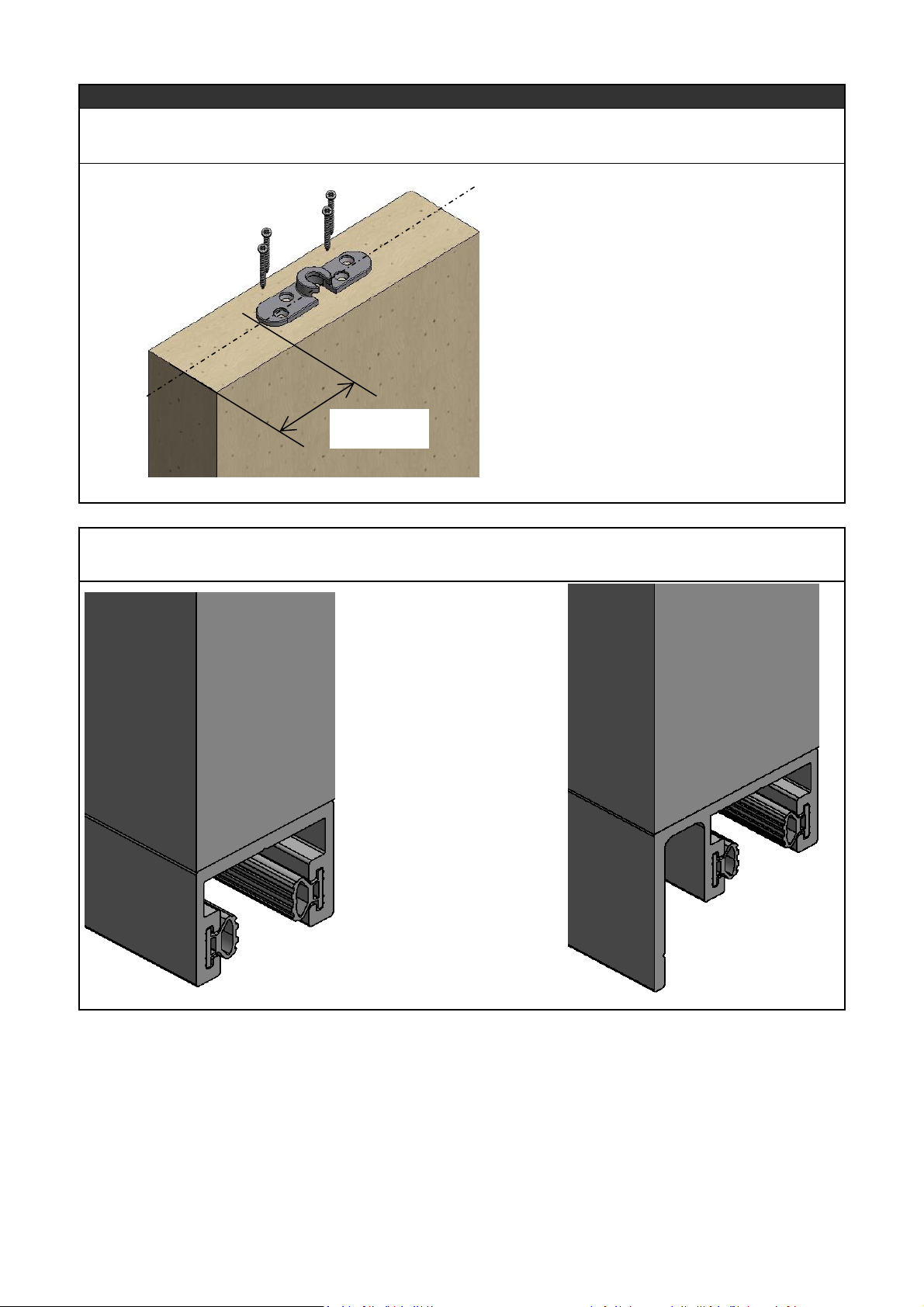
STEP 1: Position apron plates a minimum of 32mm away from the edge of the door. Ensure apron plates are
equal distance from either edge of the door. Once positioned correctly, screw into place.
STEP BY STEP INSTRUCTIONS
STEP 2: Install the U-profile channel onto the base of the shutter, fixing at 200mm intervals along the centre
line
=
=
Min 32mm
GSSUR
GSSULR
Page 3
 Loading...